TriStar TS63 User manual

Revision: 0 (September 14, 2016)
Tri-Star Industries Limited | Ambulance Operator’s Manual Page | 1
Operator’s Manual
Tri-Star Type III Ambulance
MODEL TS63
September 14, 2016
Revision: 0
TRI-STAR INDUSTRIES LIMITED
88 Forest Street, Yarmouth, Nova Scotia, Canada, B5A 4G6
Phone: +1 (902) 742-9254 | Fax: +1 (902) 742-7632
www.tri-star.ca

Revision: 0 (September 14, 2016)
Tri-Star Industries Limited | Ambulance Operator’s Manual Page | 2
Foreword
This manual is to provide the operators with the necessary information required to use this ambulance.
Included with the ambulance are manuals from equipment manufacturers. Please reference the original
equipment manufacturers manuals for service, maintenance and warranty for these individual pieces of
equipment. For the chassis component, please refer to the original vehicle chassis manual, included with
the vehicle.
If you have any questions on the operation or maintenance of this ambulance, do not hesitate to call us.
Phone Number………………………………... (902) 742-9254
Fax Number……………………………………… (902) 742-7632
Email………………………………………………... info@tri-star.ca
Website……………………………………………. www.tri-star.ca
Mailing Address………………………………… 88 Forest St, Yarmouth, Nova Scotia, B5A 4G6

Revision: 0 (September 14, 2016)
Tri-Star Industries Limited | Ambulance Operator’s Manual Page | 3
Table of Contents
Vehicle Passenger & Cargo Capacity............................................................................................................................ 5
OPERATORS MANUAL .................................................................................................................................................. 6
Electronic Control System............................................................................................................................................ 6
Overview .................................................................................................................................................................. 6
Conversion Power .................................................................................................................................................... 6
Modes of Operation................................................................................................................................................. 6
Fully Active Mode................................................................................................................................................. 6
Timer - Battery Protect Mode.............................................................................................................................. 6
Sleep-Display on Mode ........................................................................................................................................ 7
Sleep Mode .......................................................................................................................................................... 7
Down Mode.......................................................................................................................................................... 7
Control Displays ........................................................................................................................................................... 8
Overview .................................................................................................................................................................. 8
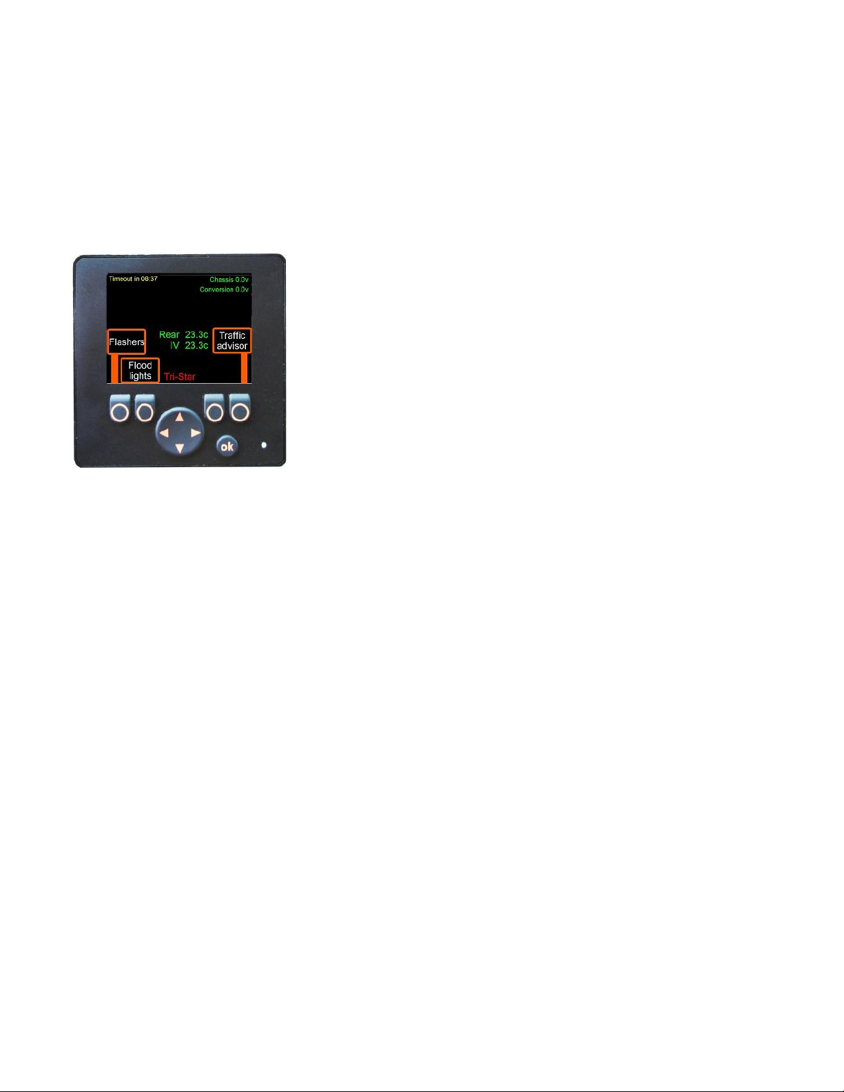
Cab Control Display –Ambulance Electrical Switches ............................................................................................. 8
Flashers (Emergency Lights)................................................................................................................................. 8
Flood lights........................................................................................................................................................... 8
Battery boost........................................................................................................................................................ 8
Traffic Advisor ...................................................................................................................................................... 9
Siren ..................................................................................................................................................................... 9
Howler.................................................................................................................................................................. 9
Lights off............................................................................................................................................................... 9
Backup alarm........................................................................................................................................................ 9
Anti-theft.............................................................................................................................................................. 9
Cab Control Display Indicators............................................................................................................................... 10
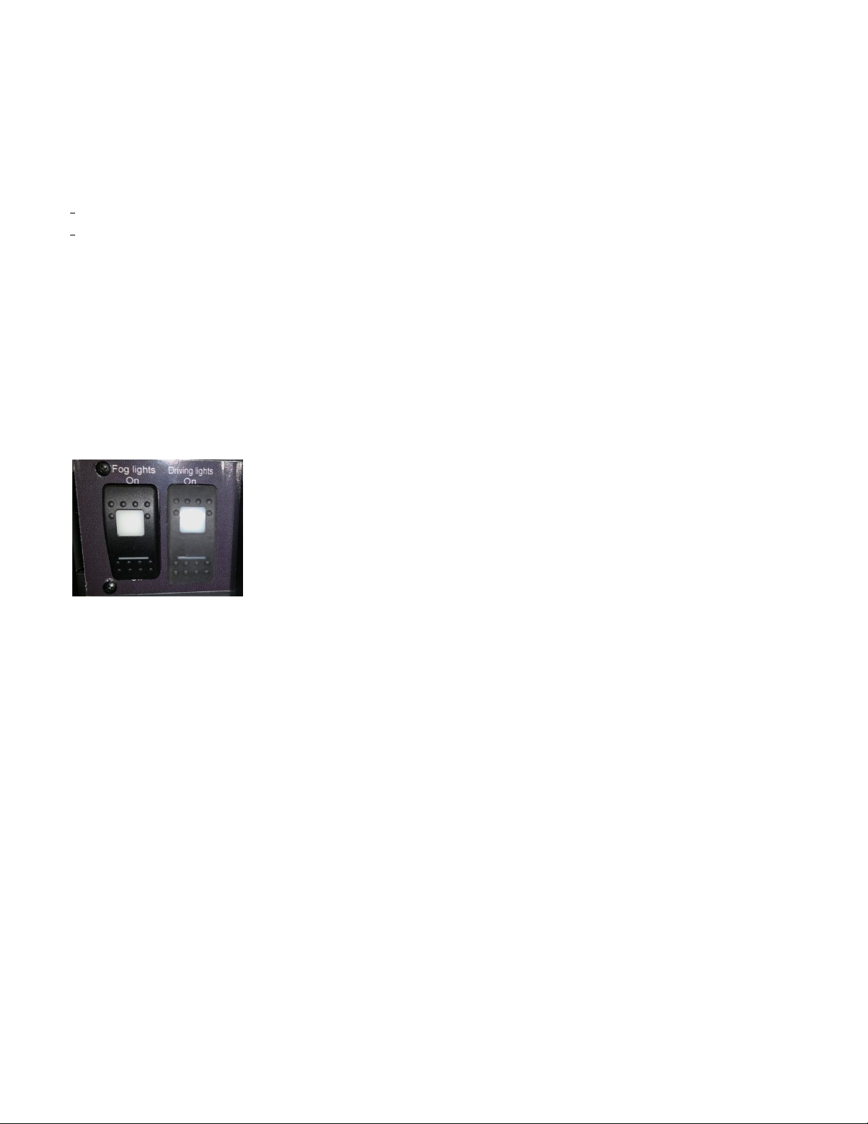
Cab Control Additional Switches............................................................................................................................ 10
Patient Compartment Control Displays –Ambulance Electrical Switches ............................................................ 11
Dome light.......................................................................................................................................................... 11
EMT light ............................................................................................................................................................ 11
Cabinet Light ...................................................................................................................................................... 11
Suction................................................................................................................................................................ 11
Patient Compartment Control Display –Rear Heating Ventilation and Air Conditioning (HVAC)......................... 12
Set Default.......................................................................................................................................................... 12
Max Output........................................................................................................................................................ 12

Revision: 0 (September 14, 2016)
Tri-Star Industries Limited | Ambulance Operator’s Manual Page | 4
Fresh air fan ....................................................................................................................................................... 12
Manual Mode..................................................................................................................................................... 13
Patient Compartment Control Display Indicators.................................................................................................. 13
Clock....................................................................................................................................................................... 13
Siren - Whelen............................................................................................................................................................ 14
Rotary Switch Operations ...................................................................................................................................... 14
Spotter Switch............................................................................................................................................................ 16
Door Locks.................................................................................................................................................................. 16
Remote Start .............................................................................................................................................................. 16
Idle Control................................................................................................................................................................. 16
Number Pad Lock....................................................................................................................................................... 16
Code red..................................................................................................................................................................... 16
110 Volt System ......................................................................................................................................................... 17
Shoreline ................................................................................................................................................................ 17
Inverter / Charger .................................................................................................................................................. 17
110v outlets ........................................................................................................................................................... 17
Heater 110v............................................................................................................................................................ 17

Revision: 0 (September 14, 2016)
Tri-Star Industries Limited | Ambulance Operator’s Manual Page | 5
Vehicle Passenger & Cargo Capacity
GVWR
5670 kg
12500 lbs
MAXIMUM DRIVER & PASSENGER CAPACITY
7 People
MAXIMUM CARGO CAPACITY
1590 kg
3511 lbs

Revision: 0 (September 14, 2016)
Tri-Star Industries Limited | Ambulance Operator’s Manual Page | 6
OPERATORS MANUAL
Electronic Control System
Overview
The Tri-Star Electronic Control System operates the ambulance electrical conversion including emergency lighting,
siren, internal lighting, heating and air-conditioning, etc. The Tri-Star Electronic Control System is a state of the art
multiplex system primarily consisting of solid state control modules and control display screens. The control
display screens are located in the cab and patient compartment and include buttons to control various ambulance
electrical components. These screens also display vehicle and system status, alarms and warnings.
Conversion Power
-Conversion power is supplied by a dedicated deep cycle battery.
-Conversion power will be shut down to conserve power when not needed.
-Conversion power can be in one of 5 Modes of Operation; Fully Active Mode, Timer - Battery Protect Mode,
Sleep-Display on Mode, Sleep Mode or Down Mode.
Modes of Operation
The Tri-Star Electronic Control System operates under various modes depending on vehicle status and time.
Fully Active Mode
When the engine is running the system is fully activated and the control displays are fully functional.
Timer - Battery Protect Mode
-When the engine transitions from running to being shut down a 10 minute timer will begin. During those 10
minutes time all electrical power is provided to the ambulance conversion except the inverter, heater and air
conditioner.
-To restart the timer and keep the system in Timer-Battery Protect Mode, press any button on the control
display, turn the ignition key, or open any door. Starting the engine will bring the system to Fully Active
Mode.
-A countdown is displayed and labeled “Timeout” on all control displays while in Timer-Battery Protect Mode.

Revision: 0 (September 14, 2016)
Tri-Star Industries Limited | Ambulance Operator’s Manual Page | 7
Sleep-Display on Mode
-After the engine has been shut down and the 10 minute Timer-Battery Protect Mode has been exhausted,
the system enters Sleep-Display on Mode. In this mode all power to the ambulance conversion is interrupted
except for the control displays, 12 volt outlets, EMT light and communications equipment. This mode
continues for 30 minutes.
-To restart the timer and keep the system in Timer- Battery Protect, press any button the on the control
display, turn the ignition key, or open any door. Starting the engine will bring the system back to Fully Active
Mode.
-A countdown is displayed and labeled “Sleep” on all control displays while in Timer-Sleep Mode.
Sleep Mode
-After 30 minutes and the Sleep-Display on Mode has been exhausted, the system enters Sleep Mode. In this
mode the control displays shut down and the ambulance conversion remains shut down except for the 12
volt outlets, and communications equipment.
-To bring the system to Timer-Battery Protect Mode, open a body door, lock or unlock the doors or turn the
key to ignition.
-Note that the vehicle will not enter Sleep mode if the key is turned to ignition or accessory, if the four way
flashers are on, park lights or headlights are on, or the service brake is held on.
Down Mode
-If the conversion battery falls below 9 volts the system completely shuts down, and can only be reactivated
when the voltage is brought up to above 12 volts. This is achieved by either running the engine or providing
power to the shoreline.
-Note that the communications equipments and 12 volt outlets are connected directly to the deep cycle
battery; therefore remain active in Down Mode.

Revision: 0 (September 14, 2016)
Tri-Star Industries Limited | Ambulance Operator’s Manual Page | 8
Control Displays
Overview
The control display is a color screen with 4 generic buttons, an “OK” button and a single larger directional button.
The screen displays the function of each generic button.
Cab Control Display –Ambulance Electrical Switches
When the system is awakened the display enters a default screen. The default screen provides control of the
following functions:
Flashers (Emergency Lights)
-Pressing the Flashers button once turns on the Flashers in PRIMARY mode and is indicated by a PRIMARY
indicator in the upper left of the display.
-Headlights will flash alternately with PRIMARY mode if headlights and park lights are off and the engine is
running.
-Pressing the Flashers button a second time activates the Flashers in SECONDARY mode and is indicated by a
SECONDARY indicator in the upper left of the display.
-Pressing the Flashers button a third time turns the Flashers off.
Flood lights
-Pressing the Flood lights button once turns on all Flood lights.
-Pressing the button a second time turns off all Flood lights.
-Note that when the park lights are on the right or left flood light will activate with the side door opening and
rear flood light with the rear doors opening. The rear flood lights will also activate when the vehicle is in
reverse.
Battery boost
-Battery boost becomes available when the key is turned to ignition or the chassis battery is below 9 volts and
the engine is not running.
-Pressing the Battery boost button while the ignition key is in the rum position will connect the boost battery
to the chassis battery for ten seconds to provide supplemental power for starting the engine.

Revision: 0 (September 14, 2016)
Tri-Star Industries Limited | Ambulance Operator’s Manual Page | 9
Traffic Advisor
-The Traffic advisor has three flash patterns: left to right, right to left, and center to ends. When the Traffic
advisor is active, an indicator light will show the direction of the flash pattern on the display.
-Pressing the Traffic advisor button once turns on the traffic advisor in a left to right flash pattern.
-Pressing the Traffic advisor button twice turns the flash pattern to right to left.
-Pressing the Traffic advisor button a third time will switch the flash pattern from the center to ends pattern.
-Press the button a fourth time will turn off the Traffic advisor.
Siren
-Siren becomes available when the engine is running; transmission is not in park and the flashers on. The siren
will operate as per the setting on the siren box.
-Pressing the Siren button will de-activate the siren box; pressing again will reactivate the siren.
-When siren is left on Hands Free it is operated by pressing the steering wheel horn when the above
conditions are met. The siren sound functions can be toggled through by pressing the horn. To stop the siren
sounds double press the horn.
-For more on the siren operation see the Siren - Whelen section below.
Howler
-Howler becomes available when the siren is operating.
-Pressing the Howler button will toggle the Howler on and off. If left on it will auto shut off after 7.5 seconds.
Lights off
-Lights off becomes available when any light in the patient compartment is turned on.
Press and hold the Light off button for three seconds to shut off all rear compartment lights.
Backup alarm
-This becomes available when reversing the vehicle and will cancel the alarm when pressed.
Note that the alarm auto starts when the vehicle starts to reverse and shuts off after 30 seconds.
Anti-theft
-Anti-theft becomes available when the engine is running, park brake is set, and transmission is in park.
-Pressing the Anti-theft button will allow the user to remove the ignition key while keeping the engine running.
-While Anti-theft is active and engaged, it can be deactivated if the park brake is released, service brake
applied or the ignition key is turned to the run position.

Revision: 0 (September 14, 2016)
Tri-Star Industries Limited | Ambulance Operator’s Manual Page | 10
Cab Control Display Indicators
Information provided on the default screen includes:
-Compartment or cab door open warning
-Hood open indicator
-Fog light on indicator
-Driving lights on indicator
-Flasher mode (PRIMARY or SECONDARY), when active
-Park Brake not set warning
-Low voltage condition warning
-Rear (patient compartment) and IV tray temperatures
-Chassis and Conversion battery voltages
-Shoreline connected warning (when vehicle is running)
-Once the vehicle is shut off the Timeout is displayed showing the remaining time before the system goes into
Timer-sleep mode.
-Once Timeout has expired the Sleep-Display on time is displayed showing the remaining time before the
system goes into Sleep mode.
Cab Control Additional Switches
Two additional switches are located next to the cab control display. These switches are for the driving lights and
fog lights.
-The fog lights are controlled by the switch labelled “Fog Lights” and activate the amber fog lights mounted on
the bumper. Fog lights will work with the engine running and not in shift park.
-The driving lights are controlled by the switch labelled “Driving Lights” and activate the clear driving lights
mounted on the bumper. The driving lights will only function when the vehicle’s lights are on and in the “High
Beam” setting while the engine is running and not in shift park.

Revision: 0 (September 14, 2016)
Tri-Star Industries Limited | Ambulance Operator’s Manual Page | 11
Patient Compartment Control Displays –Ambulance Electrical Switches
When the system is awakened the display enters a default screen. The default screen provides control of the
following functions:
Dome light
-Pressing the Dome light button once turns on all patient compartment dome lights to highest setting.
-Pressing the Dome light button a second time switches all dome lights to the mid setting.
-Pressing the Dome light button a third time switches all dome lights to the low setting.
-Pressing the Dome light button a fourth time switches all dome lights off.
EMT light
-Pressing the EMT light button once turns the EMT light on the highest setting.
-Pressing the EMT light button a second time switches the EMT light to the mid setting.
-Pressing the EMT light button a third time switches the EMT light to the low setting.
-Pressing the EMT light button a fourth time switches the EMT light off.
-Pressing and holding the EMT light button for 3 seconds toggles the BLUE reading light on and off.
Cabinet Light
-Pressing the Cabinet light once turns the Cabinet light on the highest setting.
-Pressing the Cabinet light twice turns the Cabinet light on the mid setting.
-Pressing the Cabinet light a third time turns on the Cabinet light to the low setting.
-Pressing the Cabinet light a fourth time turns the Cabinet light off.
Suction
-Pressing the Suction button once turns on the Suction pump.
-Pressing the Suction button a second time turns off the Suction pump.

Revision: 0 (September 14, 2016)
Tri-Star Industries Limited | Ambulance Operator’s Manual Page | 12
Patient Compartment Control Display –Rear Heating Ventilation and Air
Conditioning (HVAC)
HVAC settings and information screen is displayed for five seconds when the left, right or up arrow is pressed on
the default screen. The display will show the following features:
-Interior temperature
-Mode (Normal or Max)
-Set temperature (The temperature the vehicle will try to achieve when in Auto mode)
-Fresh air (The speed of the fresh air fan: off/lo/medium/high)
-HVAC Auto or Manual
Set Default
-This will enable you to change the default temperature setting in the vehicle. This is the temperature the
vehicle will try to achieve when in “Auto” mode.
-To adjust the temperature, move the up and down arrows until the desired temperature is selected, then
press ok.
Max Output
-This will switch the Heat/AC system to maximum output. This will maximize the output for the heat or AC
system as well as turn the fan on full. When active, the Mode will switch from “Normal” to “Max”.
-To switch back to normal Heat/AC system operation, press Max output again. The system will return to
“normal” mode.
Fresh air fan
This controls the level and functionality of the fan which will help circulate fresh air.
-Press the button once to turn on the fan to LO settings.
-Press the button twice to turn the fan on MEDIUM settings.
-Press the button three times to turn the fan on HIGH settings.
-Press the button four times to turn the fan on MEDIUM settings.
-Press the button five times to turn the fan on Lo settings.
-Press the button six times to turn the fan OFF.

Revision: 0 (September 14, 2016)
Tri-Star Industries Limited | Ambulance Operator’s Manual Page | 13
Manual Mode
Pressing this button will switch the HVAC control from automatic temperature control to a direct hot or cold type
control.
-Pressing Heat will switch on the heater.
-Pressing Cool will activate the Air Conditioning
-Pressing the Up and Down arrows on the center button will increase and decrease the speed of the fan.
-Pressing the Fresh Air fan will increase and decrease the speed of the fresh air fan.
-Pressing the Auto Mode will switch the HVAC controls back to automatic mode.
Patient Compartment Control Display Indicators
The information provided on the default screen is:
-Patient compartment temperature
-IV tray temperature
Clock
-The rear control display shows the time in a 24 hours:minutes:seconds format.
-If conversion battery voltage drops below 8v the clock will flash 00:00:00 until the time is set.
-To set the time; the cab control display must be used through the Menu System (see below).

Revision: 0 (September 14, 2016)
Tri-Star Industries Limited | Ambulance Operator’s Manual Page | 14
Siren - Whelen
When the requirements for the Whelen siren is met, the siren will activate (See Cab Control Display –Siren
above). The following controls are available:
POWER SWITCH - This switch has two positions: Down (Off) and Up (On). When this
switch is Off, the unit will not function. When the switch is On, the siren is functional
and may be activated at the operator’s discretion. This switch also activates control
head backlighting. NOTE: If the unit is connected to the vehicle’s horn ring circuit, the
vehicle horn is disabled when the power switch is in the ON position.
Rotary Switch - The rotary knob controls the siren functions.
There are 7 positions that may be selected. Each position and its function is outlined
under “Rotary Switch Operations.
MAN Button - The Manual button generates a variety of tones, depending on
what position the rotary knob is in. For further explanation of this button’s
function, refer to “Rotary Switch Operations.”
Rotary Switch Operations
RAD (Radio Repeat) - When the rotary knob is in the RAD position, any signal that is received by the vehicle’s
two-way radio will be simultaneously broadcast over the vehicle’s loudspeaker.
With the Rotary Switch in this Position:
-Activating the MAN button results in the AIRHORN tone until the MAN button is released.
-Activating the HORN RING input results in the AIRHORN tone until the HORN RING input is released.

Revision: 0 (September 14, 2016)
Tri-Star Industries Limited | Ambulance Operator’s Manual Page | 15
MAN 1 (Manual Siren #1) - When the rotary switch is in this position the siren is in a standby state where no
tones have been activated, but is waiting for another action to be taken by the operator.
With the Rotary Switch in this Position:
-Activating the MAN button results in the AIRHORN tone until the MAN button is released.
-Activating the HORN RING input results in the AIRHORN tone until the HORN RING input is released.
MAN 2 (Manual Siren #2) - When the rotary switch is in this position the siren is in a standby state where no
tones have been activated, but is waiting for another action to be taken by the operator.
With the Rotary Switch in this Position:
-Pressing the MAN switch will result in a WAIL tone ramping up to peak frequency and stopping when the
MAN switch is released.
-Activating the HORN RING input will result in a WAIL tone ramping up to the peek frequency and stopping
when the HORN RING input is released.
HF (Hands Free Operation) - When the rotary knob is in the HF position, the siren functions are placed in a
stand-by mode. Siren tones are activated by a single “tap” on the MAN button or on the vehicle’s steering wheel
horn ring. The first tap produces a Wail tone (a steady rise and fall tone). A second tap produces a Yelp tone (a
fast rise and fall tone). A third tap produces a Piercer™ tone (an extremely fast rise and fall tone). The next tap
returns the siren to a Wail tone and the cycle repeats itself. Two quick successive taps will stop the siren.
With the Rotary Switch in this Position:
-Pressing the MAN button will result in the HF cycle as described above.
-Activating the HORN RING input will result in the HF cycle as described above.
T1 (Tone #1) - When the rotary knob is in the T1 position, a steady, rise and fall tone (wail) is produced.
With the Rotary Switch in this Position:
-Pressing the MAN button will change the siren tone to a yelp pattern (a fast rise and fall tone). Pressing the
MAN button a second time returns it back to a wail tone.
-Activating the HORN RING input will change the siren tone to a yelp pattern. Activating the HORN RING input
again returns it back to a wail tone.
T2 (Tone #2) - When the rotary knob is in the T2 position, a fast rise and fall tone (yelp) is produced.
With the Rotary Switch in this Position:
-Pressing the MAN button will result in the Piercer™tone until the MAN button switch a second time returns it
back to Yelp.
-Pressing the HORN RING button will result in the AIRHORN tone until the HORN RING button is released.
T3 (Tone #3) - When the rotary knob is in the T3 position, an extremely fast rise and fall tone is produced.
With the Rotary Switch in this Position:
-Pressing the MAN button will result in the AIRHORN tone until the MAN button is released.
-Pressing the HORN RING button will result in the AIRHORN tone until the HORN RING button is released.

Revision: 0 (September 14, 2016)
Tri-Star Industries Limited | Ambulance Operator’s Manual Page | 16
Spotter Switch
When the vehicle is in reverse an alarm will sound. The Spotter switch is located on the rear left door will silence
the alarm for when there is a spotter to assist with the reversing.
Door Locks
For all electronic controlled doors, including main Cab, Patient and Compartment doors.
-The vehicle is fitted with a Hidden Unlock Switch located in the left front grille.
Remote Start
Pressing the key fob lock button three times within four seconds will activate the Anti-Theft function and auto
start the vehicle.
Idle Control
When the engine is idling, the system will monitor the interior temperatures and battery voltages. If they meet
set levels the idle control will shutdown the engine. The system continues to monitor and if the set levels are not
reached the engine will auto start again. If the engine has shut down automatically, it can be restarted manually
by pressing the brake pedal or cycling the key off to on.
Idle control will not activate when the hood is open.
Idle control will only start after the engine has been running for 5 minutes.
Please note that the idle function will function as described here, even when the vehicle’s “anti-theft” mode has
been activated.
Number Pad Lock
-The number pad lock controls access to the lower drawer on the right wall cabinet.
-To unlock and access the cabinet, enter the number code and open the drawer.
-See the schematics drawing for how to program the unit in the Service manual
Code red
-The vehicle is fitted with a Code red switch located under the EMT area display.
-Code red will show on all displays until either the vehicle is placed in park, or the switch is held for about 2
seconds.

Revision: 0 (September 14, 2016)
Tri-Star Industries Limited | Ambulance Operator’s Manual Page | 17
110 Volt System
The ambulance is fitted with a 110V system consisting of an external shoreline and an inverter/battery charger.
A breaker box mounted in the exterior control center contains lighted breaker switches for block heater, 110v
heater and battery charger/110v outlets.
Shoreline
-A 30-amp shore line inlet with an auto-eject function is located at the left front of the body box.
-The shoreline should be connected while vehicle is not in use to maintain battery voltage.
-A shoreline indicator on the front control display will activate when shoreline is connected and 110 volt power
is present.
-When the vehicle is started, the system will eject the shoreline automatically.
Inverter / Charger
-An inverter (1000w) will supply power to 110v outlets when the shoreline is disconnected and the engine is
running.
-The inverter will activate when the engine is started and deactivate when the engine is shutdown.
-The inverter is disconnected automatically when shoreline is supplied power.
-The inverter/charger will charge the vehicles batteries when the shoreline is supplied power.
110v outlets
-110v outlets are powered from the shoreline or inverter unit.
-110v outlets are GFI protected. GFI is located on inverter outlet.
-1 or more outlets are lighted when supplied 110v power.
Heater 110v
-A heater is powered from the shoreline through a breaker in the 110v electrical box.
Table of contents
Popular Control System manuals by other brands

Linear Access
Linear Access AM/II Installation and programming instructions

AheadX
AheadX LEO installation manual

Ruida Technology
Ruida Technology LFS-PM Series operating manual

Bosch
Bosch Rexroth IndraMotion MTX 09VRS manual

btsr
btsr SMART MATRIX WINDINGFEEDER operating manual

Philips
Philips Lytemode 6-Button Remote Station user guide

Briggs & Stratton
Briggs & Stratton Symphony II Installation & operator's manual

heat-timer
heat-timer Mini-MOD Installation and operation instruction

Balboa
Balboa Hydro Air 20-0244 quick start guide

Russound
Russound A-BUS brochure

HBX
HBX Snowmelt Controller 1000 installation manual

GRAUPNER
GRAUPNER MC-22S Programming manual