Duro Dyne DuroZone RED-4 User manual

®
MODEL RED-4
ZONE CONTROL SYSTEM
PART# 35234
Corporation
DuroZone®
is a division of
®
DuroZoneDuroZone
RED4 InstrManual-7-1-10.indd 1 7/9/2010 5:34:36 PM

• Panel controls four zones.
• Zone4 damper can be used as a fresh air
damper. A timer on panel sets the minutes
of fresh air per hour.
• Capable of two-stage heating and two-
stage cooling for gas/electric systems and
three-stage heating and two-stage cooling
for heat pump systems.
• Compatible with gas/electric, oil, electric
andhydronicsystemsandbothconventional
and dual fuel heat pumps. An optional
supply air temperature sensor can be used
to limit supply air temperature and prevent
over-heating and freeze-up. Maximum and
minimum supply air temperatures can be
set on the panel.
• Optional outdoor air temperature sensor
can be used to limit multi stage heating in
moderate weather.
• Optional outdoor air temperature sensor
used with dual fuel heat pumps to control
switch-over to fossil fuel heating without
the use of external thermostats or relays.
• Compatible with low cost, heat-cool
thermostats.
• Compatible with automatic change-over
thermostats allowing any zone to call for
heating or cooling.
• Second and third stage startup controlled
by a timer located on the panel.
• A heat pump thermostat can be used in
Zone1 for emergency heat control.
• An optional purge cycle at the end of
heating or cooling call.
• Limit use of multi stage heating and cooling
when less than half the zones are calling.
• One-Zone operation eliminates resetting all thermostats when going on vacation. All dampers and HVAC system are
controlled by the Zone1 thermostat.
• Compatible with most 24VAC powered and battery powered thermostats.
• Compatible with all 24VAC damper actuators including spring return and power open/power close types.
RED4 - Zoning Panel
FEATURES
DuroZone RED4 - INSTALLATION INSTRUCTIONS PAGE 2
DuroZone recommends this control panel be mounted in a conditioned space.
IMPORTANT:
RED4 InstrManual-7-1-10.indd 2 7/9/2010 5:34:37 PM

The RED4 is a 4-zone panel that can control gas/
electric, hydronic, electric and both conventional
and dual fuel heat pumps with multi-stage heating
and cooling. Low cost heat/cool thermostats can
be used in all zones. Optionally, a heat pump
type thermostat can be used in Zone1.
Selecting Equipment Options
DIP switches 1, 2 and 3 select the type of HVAC system
that is being used. The panel is factory set for a Gas-Electric
system with Gas Fan operation.
Selecting a Gas-Electric or a Heat Pump System
The panel will operate with gas-electric, oil, hydronic and
electric HVAC systems when DIP switch #1 is in the OFF
position. The panel will operate with heat pump systems
when DIP switch #1 is in the ON position.
Selecting Conventional or Dual Fuel Heat
Pump System
When DIP switch #1 is set to select heat pump operation,
DIP switch #2 selects a conventional heat pump or a dual
fuel heat pump. For conventional heat pumps the panel will
activate stage one and two compressors (Y1 and Y2). In
third stage heating the panel will activate both compressors
and the auxiliary heating (W2). For dual fuel heat pumps
only the auxiliary heating (W2) is activated during third
stage heating calls.
Selecting Gas or Electric Fan Operation
DIP switch #3 selects Gas or Electric Indoor Fan operation.
In Gas mode the fan is not turned on by the panel during
a heating call. A sensor or timer in the furnace will
automatically turn the fan on.
In Electric operation, the panel turns the fan on during
heating calls. Selecting a heat pump system will automatically
turn the fan on during heating calls. If a dual fuel heat pump
is used, DIP switch #3 selects whether the fan is operated
during calls using the auxiliary fuel system for heating.
In both Gas-Electric and Heat Pump Systems, the indoor fan
is activated during cooling calls.
Selecting the Type of Thermostat in Zone1
DIP switch #4 selects the type of thermostat being used in
Zone1. For heat pump systems, a heat pump thermostat may
be selected for Zone1 to provide emergency heat control on
the thermostat. When using a heat/cool thermostat for heat
pump systems the emergency heat can be controlled by the
Emergency Heat slide switch on the panel or an external
switch. Do not use the panel switch or the external switch
DuroZone RED4 - INSTALLATION INSTRUCTIONS PAGE 3
INSTALLATION INSTRUCTIONS if Dip switch #4 is set to HP.
Selecting Purge Control
DIP switch #5 selects whether the heated or cooled air
stored in the system at the end of a heating or cooling cycle
is purged by the panel. If purge is controlled by the panel,
the indoor fan will be operated for 90 seconds at the end of
the call to purge the system. During purge the dampers will
remain in the position just before purge and purged air goes
to the last zone calling.
Selecting Capacity Limit Control
DIP switch #6 selects whether multi stage heating or cooling
will be inhibited if only half or less of the zone(s) are calling
for heating or cooling.
Selecting Outdoor Temperature Limit Control
DIP switch #7 selects whether multi stage heating will be
inhibited if the outdoor temperature is above the temperature
set on the ODT Limit potentiometer. Note: For dual fuel
heat pumps, switch #7 must be off (in the NO position)
if the heat pump automatically switches to the auxiliary
heating system when the outdoor temperature drops below
the temperature set on the ODT Limit potentiometer.
Selecting Opposite System Service
The panel will normally service heating or cooling based on
whether there are more heating or more cooling calls.
If Opposite System service is selected using DIP switch
#8 , the panel will switch to the opposite system after calling
continuously for 20 minutes even though there may be only
one zone calling for the opposite system.
RED4 InstrManual-7-1-10.indd 3 7/9/2010 5:34:40 PM

24VAC Power
24VAC is connected to the panel at the terminals marked
24VAC. A 40VA transformer should be used and the
output connected to terminals 1 and 2 (not polarized). A
circuit breaker type fuse is located next to the terminals. If a
short should occur in the damper or thermostat wiring, the
Fuse will open the circuit and then close the circuit when the
short is removed.
WARNING! THE FUSE GETS VERY HOT WHEN
A SHORT OCCURS AND SHOULD NOT BE
TOUCHED.
PLEASE NOTE: YOU MUST USE AN INDEPEN-
DENT LOW VOLTAGE POWER SUPPLY.
Heating Limit Potentiometer
This potentiometer sets the maximum Supply Air Plenum
temperature allowed in heating. A low cost Supply Air
Sensor can be used to monitor the temperature and if the
supply air temperature exceeds the set Heating Limit, the
heat is turned off and the indoor fan is activated. After two
minutes the heat will be turned back on if the supply air has
dropped below the Heating Limit.
Cooling Limit Potentiometer
This potentiometer sets the minimum Supply Air Plenum
temperature allowed in cooling. If the supply air temperature
drops below the set Cooling Limit, the cooling is turned off
and the indoor fan is activated. After two minutes the cooling
will be turned back on if the supply air has risen above the
Cooling Limit.
W2/W3/Y2 Timer Potentiometer
Second and third stage heating and second stage cooling
are controlled by a timer. If the panel has been calling for
heating or cooling longer than the time set on the W2/
W3/Y2 Timer potentiometer, the second stage heating
or cooling will be activated provided it is not inhibited by
the Outdoor Temperature Limit or the Capacity Limit. If
the panel has been calling for second stage heating longer
than the time set on the W2/W3/Y2 Timer Potentiometer,
the Third Stage Heating will be activated provided it is not
inhibited by a limit.
Selecting Use of Zone4 Damper
Dip switch #9 selects whether Damper4 is being used as
Zone4 damper or as a fresh air damper. When it is used as
a fresh air damper, the minutes per hour of fresh air is set
on the panel.
Selecting One-Zone Operation
The panel can be operated as a single (one-zone) system.
The panel will control all the dampers together based on the
Zone1 thermostat.
This can eliminate the need to change all the thermostats
when the home or building is vacant such as at night or
during vacation periods.
One-Zone operation can be selected using the 1ZNE switch
on the panel or an external switch. The LED adjacent to
the switch will be activated when One-Zone operation is
selected.
Emergency Heat Operation
Emergency Heat can be selected from Zone 1 when using
a heat pump thermostat. When using a conventional heat/
cool thermostat the Emergency Heat can be selected on
the panel switch or an external switch. If emergency heat is
activated by the panel switch or an external switch, the LED
adjacent to the switch will be lit. Any heating calls from any
thermostat will be treated as emergency heat calls.
The emergency heat switch on the panel or an external switch
cannot be used when Dip switch #4 is set to heat pump
thermostat. The emergency heat switch on the thermostat
must be used in this mode.
If an emergency heat call is initiated by a heat pump thermostat
in Zone1, an emergency heat call will occur. The panel will
treat all calls for heating as emergency heat calls until Zone1
calls for a non-emergency heat call or a cooling call.
Timer Reset Switch
Momentarily pressing the Timer Reset switch clears the
built-in timers allowing the system to be checked out more
quickly.
DuroZone RED4 - INSTALLATION INSTRUCTIONS PAGE 4
R
EXTERNAL
SWITCH
1ZNE
R
EXTERNAL
SWITCH
W2/E
2
4
V
A
C
1
2
RED4 InstrManual-7-1-10.indd 4 7/9/2010 5:34:42 PM

ODT Limit Potentiometer
A low cost Outdoor Air Sensor can be used to monitor
the outdoor temperature and if the outdoor temperature is
greater than the ODT Limit, multi stage heating is inhibited
if the option was selected.
In a dual fuel heat pump, the ODT Limit is used to
automatically switch the panel to the auxiliary heating
system.
FA Timer Potentiometer
When Damper4 is used as a fresh air damper, the
minutes of fresh air per hour can be set on the FA Timer
potentiometer. The fresh air minutes will try to be fulfilled
during a heating or cooling call. If the fresh air minutes
cannot be fulfilled during a call, Damper4 will be opened
and the indoor fan will be activated.
Damper LEDs
Any of the four green damper LEDs will light when the
damper represented by that LED is in the open position.
A damper LED will blink if it detects a zone thermostat is
calling for both heating and cooling that may be caused by
a shorted wire.
System LEDs
The nine red LEDs indicate the status of the HVAC
system. Each LED will indicate by being lit continuously
or blinking.
DuroZone RED4 - INSTALLATION INSTRUCTIONS PAGE 5
Fan LED
The Fan LED will be lit continuously when the panel
is in continuous indoor fan operation. The Fan LED
will blink when the system is in Purge mode.
Cool LED
The Cool LED will be lit continuously when the
panel is calling for first stage cooling. The Cool
LED will blink when the panel is calling for second
stage cooling.
Heat LED
The Heat LED will be lit continuously when the
panel is calling for first stage heating. The Heat
LED will blink when the panel is calling for second
stage heating.
Status LED
The Status LED blinks continuously when the
panel is powered and indicates the microprocessor
is operating properly. If the Status LED is on and
not blinking, the automatic contractor test is in
progress.
SA Limit LED
The SA Limit LED is on continuously when a
Supply Air Sensor is installed. The SA Limit LED
blinks when the panel is in supply air limit status
(Heating or Cooling temperature exceeded).
ODT Limit LED
The ODT Limit LED is on continuously when an
Outdoor Air Sensor is installed. The ODT Limit
LED blinks when the panel is inhibiting second
stage calls because of ODT Limit or the dual fuel
heat pump has switched to the auxiliary heating
system.
Capacity Limit LED
The Capacity Limit LED is on continuously when
the panel is in stand by mode for capacity limit.
The Capacity limit LED will flash when inhibiting
multi stage heating and cooling because half or less
of the zones are calling.
Emergency Heating LED
The Emergency Heating LED is on continuously
when the panel is in the emergency heat mode and
will blink during an emergency heat call.
Fresh Air Cycle LED
The FA Cycle LED is on continuously when the
fresh air damper mode is selected and blinks when
the damper is opened for fresh air.
ODT LIMIT
RED4 InstrManual-7-1-10.indd 5 7/9/2010 5:34:44 PM

Wiring Instructions
All wiring should be done in accordance with local
and national codes. Use color-coded, multi-conductor
thermostat wire.
THESE PANELS ARE DESIGNED FOR USE
WITH 24VAC CONTROLS AND SHOULD
NOT BE USED WITH OTHER VOLTAGES. USE
CAUTION TO AVOID ELECTRIC SHOCK OR
DAMAGE TO EQUIPMENT.
Wiring the Supply Air Sensor
To install the optional Supply Air Sensor, connect two
wires to the Supply Air Sensor and to the two terminals
marked “SAS” on the panel.
The Supply Air Sensor should be installed in the Supply Air
Plenum so that it measures the supply air temperature.
Wiring the Outdoor Air Temperature Sensor
To install the optional Outdoor Air Temperature Sensor,
connect two wires to the Outdoor Air Sensor and to the
two terminals marked “OAS” on the panel.
The Outdoor Air Temperature Sensor should be installed
outside and in a shaded location.
Wiring Zone Thermostats
All zones can use low cost, heat/cool thermostats as shown
below. Be sure to set DIP switch #4 to HC if a heat/cool
thermostat is used in Zone1.
Wiring Dampers
The panel can be used with any 24VAC power open/power
close or spring return damper. Terminal M1 is 24VAC
common, M2 is 24VAC, M4 is 24VAC when the panel
opens the damper and M6 is 24VAC when the panel closes
the damper.
Wiring diagram for DuroZone MB, MS, or RD type
damper.
Wiring diagram for a spring return damper that is normally
closed with no power (spring closed).
Heat/Cool Thermostat
A heat pump thermostat can be used in Zone1 to provide
emergency heat control from the thermostat. Be sure to set
DIP switch #4 to HP.
DuroZone RED4 - INSTALLATION INSTRUCTIONS PAGE 6
Heat/Cool Thermostat
RED4 InstrManual-7-1-10.indd 6 7/9/2010 5:34:46 PM

Wiring diagram for a spring return damper that is normally
open with no power (spring open).
DuroZone RED4 - INSTALLATION INSTRUCTIONS PAGE 7
*NOTE 1: Sometimes Y needs to be wired to the
furnace for fan speed.
RC
RH
O
Y1
G
W2/E
W1/B
G
C
Y2
COMMON
LINE
VOLTAGE 24VAC
R
C
RH-RC
JUMPER
#/.$%.3).'5.)4
/),&52.!#%
Y1
FIRST STAGE
COOLING
SECOND STAGE
COOLING
Y2
FAN
OIL BURNER
CIRCULATOR RELAY OR
HOT WATER VALVE
#UT*UMPER
RED4 Panel
RC
RH
O
Y1
G
W2/E
W1/B
G
C
Y2
MULTI STAGE
GAS/ELECTRIC SYSTEM
COMMON
LINE
VOLTAGE 24VAC
R
C
RH-RC
JUMPER
#/.$%.3).'5.)4
W2
&52.!#%
W1
3%%./4%
Y1
FIRST STAGE
COOLING
SECOND STAGE
COOLING
Y2
FIRST STAGE
HEATING
SECOND STAGE
HEATING
Y
FAN
FAN SPEED
*NOTE 1: Sometimes Y needs to be wired to the
furnace for fan speed.
RED4 Panel
Wiring an HVAC System
The panel can be used with a wide variety of HVAC systems.
Some of the more common configurations follow:
PLEASE NOTE: THE RED4 PANEL MUST
BE POWERED BY AN INDEPENDENT LOW
VOLTAGE POWER SUPPLY AND NOT BY THE
EQUIPMENT LOW VOLTAGE POWER SUPPLY.
RC
RH
O
Y1
G
W2/E
W1/B
G
C
Y2
REVERSING VALVE
COOLING
LINE
VOLTAGE 24VAC
R
C
RH-RC
JUMPER
HEAT PUMP
AIR HANDLER
Y1
FIRST STAGE
SECOND STAGE
Y2
FAN
R
O
W
24VAC
DEFROST
W
ELECTRIC
STRIP HEAT
*Wire the
W1/B to
heat pump
if valve
reverses in
the heat
mode.
*
RED4 Panel
•
RC
RH
O
Y1
G
W2/E
W1/B
Y
C
Y2
REVERSING VALVE
COOLING
LINE
VOLTAGE 24VAC
R
C
RH-RC
JUMPER
&52.!#%
Y1
FIRST STAGE
SECOND STAGE
Y2
R
O
W
24VAC
DEFROST
G
FAN
7IRE
THE
7"TO
HEAT
PUMPIF
VALVE
REVERSES
INTHE
HEAT
MODE
W2
W1
FIRST STAGE
SECOND STAGE
3%%./4%
RED4 Panel
Heat PumP
•
•
RED4 InstrManual-7-1-10.indd 7 7/9/2010 5:34:49 PM

DuroZone RED4 - INSTALLATION INSTRUCTIONS PAGE 8
Automatic Contractor Test (Version 1.70)
The Automatic Contractor Test (ACT) can
be started at any time by pressing and holding
the Timer Reset switch for 10 seconds.
The test can be terminated at any time by
pressing the Timer Reset switch again.
When the test is started all calls are terminated and
all dampers will be closed. The Status LED will be on
continuously during the test.
Step1. Zone1 Thermostat Test
The DPR1 LED will turn On and
the Cool, Heat, Fan, or EM Heat
LED will turn On indicating the
state of the Zone1 thermostat. If
the Cool, Heat, Fan and EM Heat
LEDs are all Off, there is no call at
the thermostat. Step 1 will run 30
seconds.
Step2. Zone2 Thermostat Test
Now the DPR2 LED will turn On
and the Cool, Heat, Fan, or EM
Heat LED will turn On indicating
the state of the Zone2 thermostat.
Step 2 will run 30 seconds.
Step3. Zone3 Thermostat Test
Now the DPR3 LED will turn On
and the Cool, Heat, Fan, or EM
Heat LED will turn On indicating
the state of the Zone3 thermostat.
Step 3 will run 30 seconds.
Step4. Zone4 Thermostat Test
Now the DPR4 LED will turn On
and the Cool, Heat, Fan, or EM
Heat LED will turn On indicating
the state of the Zone4 thermostat.
Step 4 will run 30 seconds.
Step5. Damper Test
Now all of the dampers will be
opened and the indoor fan is
activated. Step 5 will run for 1
minute. You can terminate the
test at this time by pressing the
Timer Reset switch. You might want to change
the thermostats and again run the test.
Step6. Damper4 Test
Now Damper4 will close and the indoor fan
remains activated. If Damper4 is used as a zone
damper you should not feel airflow at Zone4
and the other zones should be open. The DPR4
LED will be OFF. If Damper4 is used as a fresh
air damper it also should be closed. Step 6 will
take 1 minute.
Step7. Damper3 Test
Now the Damper3 will close and the indoor fan remains
activated. You should not feel airflow at Zone3 and the
other zones should be open. The DPR3 LED will be OFF.
Step 7 will run 1 minute.
Step8. Damper2 Test
Now Damper2 will close and the indoor fan remains
activated. You should not feel airflow at Zone2 and the
other zones should be open. The DPR2 LED will be OFF.
Step 8 will take 1 minute.
Step9. Damper1 Test
Now Damper1 will close and the indoor fan remains
activated. You should not feel airflow at Zone1 and the
other zones should be open. The DPR1 LED will be OFF.
Step 9 will take 1 minute.
Step10. Stage1 Heating Test
All dampers will be open now and the stage1 heating is
activated. Check that heated air is entering the zones.
The Heat LED will be On continuously. Step 10 will run
1 minute.
Step11. Stage2 Heating Test
Now the stage2 heating is also activated. Check that
heated air is entering the zones. The Heat LED will be
blinking. Step 11 will run 1 minute if it is on a Heat
Pump System. Add 1 minute if not on a Heat Pump for
the purge cycle.
Step12. Stage3 Heating Test
If a heat pump is selected, the third stage heating will be
activated for 1 minute. Then the heating will be turned
Off and the indoor fan run for 1 minute to purge the
heat. Step 12 will run 2 minutes.
Step13. Stage1 Cooling Test
The Stage1 cooling is now turned On and Cool LED will
be On. Check that cool air is entering the zones. Step 13
will run 1 minute.
Step14. Stage2 Cooling Test
Now the Stage2 cooling is also turned On and Cool LED
will blink. Check that cool air is entering the zones. Step
14 will run 1 minute.
After the stage2 cooling has run for 1 minutes the cooling
will be turned Off. The indoor fan will run for 1 minute
to purge the cooling and then the panel will return to
normal operation.
For the most updated product information,
please visit our website
www.durodyne.com
©2010 Duro Dyne Corporation
Printed in USA 6/2010
BP035428
RED4 InstrManual-7-1-10.indd 8 7/9/2010 5:34:53 PM

DuroZone RED4 - INSTRUCCIONES DE INSTALACIÓN PÁGINA 8
©2010 Duro Dyne Corporation
Impreso en EE.UU. 6/2010
BP035428
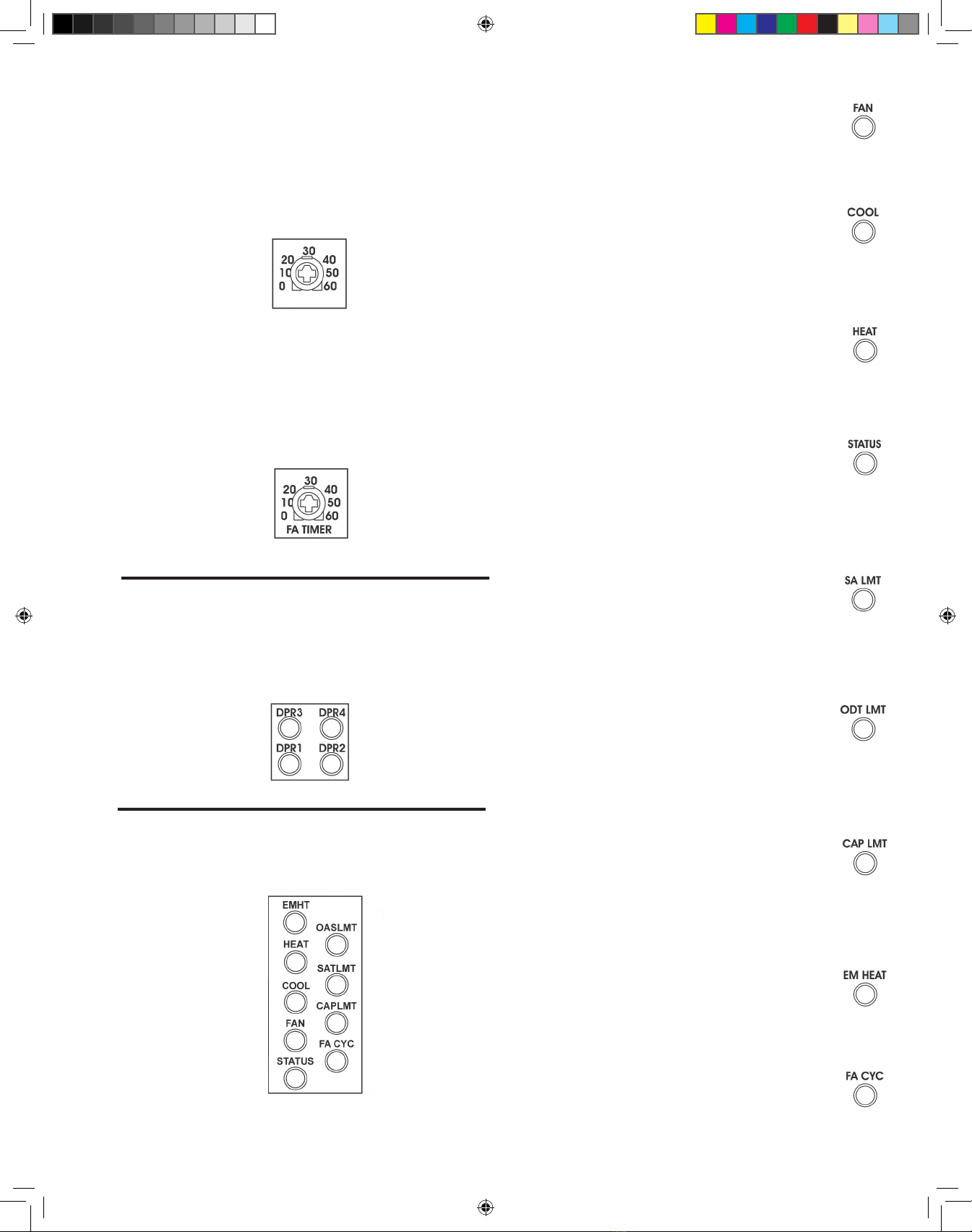
Paso 7. Prueba del compuerta de aire (damper) 3
En este momento, se cierra el compuerta de aire (damper) 3 y se
activará el ventilador interior. Non deberá notar flujo de aire en la
zona 3 y las demás zonas si quiedan abiertas. El indicador LED DPR3
permanecerá encendido. Este paso 7 tiene duracion de 1 minuto.
Paso 8. Prueba del compuerta de aire (damper) 2
En este momento, se cierra el compuerta de aire (damper) 2 y se
activará el ventilador interior. Non deberá notar flujo de aire en la
zona 2 y las demás zonas si quiedan abiertas. El indicador LED DPR2
permanecerá encendido. Este paso 8 tiene duracion de 1 minuto.
Paso 9. Prueba del compuerta de aire (damper) 1
En este momento, se cierra el compuerta de aire (damper) 1 y se
activará el ventilador interior. Non deberá notar flujo de aire en la zona
1 y las demás zonas si quiedan abiertas. El indicador LED DPR1
permanecerá encendido. Este paso 9 tiene duracion de 1 minuto.
Paso 10. Prueba de calefacción de primera etapa
Se abrirán los compuertas de aire (dampers) y se activará la
calefacción de primera etapa. Compruebe que el aire calefactado
entra en las zonas. El indicador LED HEAT permanecerá encendido
continuamente. Este paso 10 tiene duracion de 1 minuto.
Paso 11. Prueba de calefacción de segunda etapa
En este momento, también se activará la calefacción de segunda
etapa. Compruebe que el aire calefactado entra en las zonas. El
indicador LED HEAT parpadeará. Este paso 11 tiene duracion de 1
minuto si en el Heat Pump. Agregar 1 minuto si en el sistema no esta
con el Heat Pump en sistema purga.
Paso 12. Prueba de calefacción de tercera etapa
Si se selecciona una bomba de calefacción, se activará la calefacción
de tercera etapa durante 2 minutos. La calefacción se apagará y
el ventilador interior funcionará durante 1 minuto para purgar el
aire calefactado. Este paso 12 tiene duracion de 2 minutos.
Paso 13. Prueba de refrigeración de primera etapa
La refrigeración de primera etapa se enciende en este momento
y el indicador LED COOL se enciende. Compruebe que el aire
refrigerado entra en las zonas. Este paso 13 tiene duracion de 1 minuto.
Paso 14. Prueba de refrigeración de segunda etapa
En este momento, la refrigeración de segunda etapa también se
enciende y el indicador LED COOL parpadea. Compruebe que el aire
refrigerado entra en las zonas. Este paso 14 tiene duracion de 1 minuto.
Tras ejecutarse la refrigeración de segunda etapa durante 1 minuto,
la refrigeración se apaga. El ventilador interior funcionará durante
2 minutos para purgar la refrigeración. El indicador LED FAN
parpadeará durante la purga y pasados 2 minutos el panel volverá
al funcionamiento normal.
Prueba automática del contratista (Versión 1.7)
La prueba automática del contratista puede iniciarse en
cualquier momento manteniendo pulsado el interruptor
TIMER RESET durante 10 segundos. La prueba puede
concluirse en cualquier momento volviendo a pulsar el
interruptor TIMER RESET.
Al final de la prueba se finalizan todas las solicitudes y se
cierran todas las compuertas de aire (dampers). El indicador
LED STATUS permanecerá encendido continuamente
durante la prueba.
Paso 1. Prueba del termostato de la zona 1
El indicador LED DPR1 se encenderá y los indicadores LED COOL,
HEAT, FAN o EM HEAT se encenderán
indicando el estado del termostato de la zona
1. Si los indicadores LED COOL, HEAT,
FAN y EM HEAT están todos apagados, no
hay ninguna solicitud en el termostato. Este
paso 1 tiene duracion de 30 segundos.
Paso 2. Prueba del termostato de la zona 2
En este momento, el indicador LED
DPR2 se encenderá y los indicadores
LED COOL, HEAT, FAN o EM HEAT
se encenderán indicando el estado del
termostato de la zona 2. Este paso 2
tiene duracion de 30 segundos.
Paso 3. Prueba del termostato de la zona 3
En este momento, el indicador LED
DPR3 se encenderá y los indicadores
COOL, HEAT, FAN o EM HEAT se
encenderán indicando el estado del
termostato de la zona 3. Este paso 3
tiene duracion de 30 segundos.
Paso 4. Prueba del termostato de la zona 4
En este momento, el indicador LED
DPR4 se encenderá y los indicadores
LED COOL, HEAT, FAN o EM HEAT
se encenderán indicando el estado del
termostato de la zona 4. Este paso 4
tiene duracion de 30 segundos.
Paso 5. Pruebe del regulador (damper)
Ahora,todoslosreguladores,(dampers)
se abrirán y el ventilador interior se
activará. Este paso 5 tiene duracion de
1 minuto.
Puede finalizar la prueba en este momento volviendo a pulsar
el interruptor TIMER RESET. Puede cambiar los termostatos y
volver a ejecutar la prueba.
Paso 6. Prueba del compuerta de aire (damper) 4
En este momento, se cierra el compuerta de aire
(damper) 4 y se activará el ventilador interior. Si
el compuerta de aire (damper) 4 se utiliza como
compuerta de aire (damper) de zona, non deberá
notar flujo de aire en la zona 4 y las demas zonas si
quiedan abiertas. El indicador LED DPR4 permanecerá
encendido. Si el compuerta de aire (damper) 4 se
utiliza como compuerta de aire (damper) de aire
fresco, deberá comprobar la entrada de aire. Este
paso 6 tiene duracion de 1 minuto.
Visite nuestro sitio web para
informacion actualizada de nuestros
productos: www.durodyne.com
RED4 InstrManual-7-1-10.indd 9 7/9/2010 5:34:57 PM

Diagrama de cableado para compuerta de aire (damper) de retorno
por resorte que normalmente está abierto sin alimentación (resorte
abierto).
DuroZone RED4 - INSTRUCCIONES DE INSTALACIÓN PÁGINA 7
RC
RH
O
Y1
G
W2/E
W1/B
G
C
Y2
COMMON
LINE
VOLTAGE 24VAC
R
C
RH-RC
JUMPER
#/.$%.3).'5.)4
/),&52.!#%
Y1
FIRST STAGE
COOLING
SECOND STAGE
COOLING
Y2
FAN
OIL BURNER
CIRCULATOR RELAY OR
HOT WATER VALVE
#UT*UMPER
RED4 Panel
RC
RH
O
Y1
G
W2/E
W1/B
G
C
Y2
MULTI STAGE
GAS/ELECTRIC SYSTEM
COMMON
LINE
VOLTAGE 24VAC
R
C
RH-RC
JUMPER
#/.$%.3).'5.)4
W2
&52.!#%
W1
3%%./4%
Y1
FIRST STAGE
COOLING
SECOND STAGE
COOLING
Y2
FIRST STAGE
HEATING
SECOND STAGE
HEATING
Y
FAN
FAN SPEED
RED4 Panel
RC
RH
O
Y1
G
W2/E
W1/B
G
C
Y2
REVERSING VALVE
COOLING
LINE
VOLTAGE 24VAC
R
C
RH-RC
JUMPER
HEAT PUMP
AIR HANDLER
Y1
FIRST STAGE
SECOND STAGE
Y2
FAN
R
O
W
24VAC
DEFROST
W
ELECTRIC
STRIP HEAT
*Wire the
W1/B to
heat pump
if valve
reverses in
the heat
mode.
*
RED4 Panel
•
RC
RH
O
Y1
G
W2/E
W1/B
Y
C
Y2
REVERSING VALVE
COOLING
LINE
VOLTAGE 24VAC
R
C
RH-RC
JUMPER
&52.!#%
Y1
FIRST STAGE
SECOND STAGE
Y2
R
O
W
24VAC
DEFROST
G
FAN
7IRE
THE
7"TO
HEAT
PUMPIF
VALVE
REVERSES
INTHE
HEAT
MODE
W2
W1
FIRST STAGE
SECOND STAGE
3%%./4%
RED4 Panel
Heat PumP
•
•
Cableado del sistema de calefacción, ventilación y
aire acondicionado
El panel puede utilizarse con una amplia variedad de sistemas de
calefacción, ventilación y aire acondicionado. A continuación se
indican algunas de las configuraciones más comunes:
RECUERDE: EL PANEL RED4 DEBE ACTIVARSE
MEDIANTE UNA FUENTE DE ALIMENTACIÓN DE
BAJA TENSIÓN INDEPENDIENTE Y NO A TRAVÉS
DE LA FUENTE DE ALIMENTACIÓN DE BAJA
TENSIÓN DEL EQUIPO.
*NOTA 1: A veces Y tiene que conectarse a la
caldera para la velocidad de ventilador.
*NOTA 1: A veces Y tiene que conectarse a la
caldera para la velocidad de ventilador.
RED4 InstrManual-7-1-10.indd 10 7/9/2010 5:34:59 PM

Instrucciones de cableado
Todo el cableado debe realizarse de acuerdo con la normativa
local y nacional. Utilice cables de termostato policonductores con
código de colores.
ESTOS PANELES ESTÁN DISEÑADOS PARA SU
USO CON CONTROLES DE 24 V DE CA Y NO
DEBEN UTILIZARSE CON OTRAS TENSIONES
TENGA CUIDADO PARA EVITAR DESCARGAS
ELÉCTRICAS O DAÑOS EN EL EQUIPO.
Cableado del sensor del suministro de aire
Para instalar el sensor del suministro de aire, conecte dos cables al
sensor del suministro de aire y a los dos terminales marcados como
SAS en el panel.
El sensor del suministro de aire debe instalarse en el impelente del
suministro de aire para que mida la temperatura del suministro de
aire.
Cableado del sensor de temperatura de aire exterior
Para instalar el sensor de temperatura de aire exterior opcional,
conecte dos cables al sensor de aire exterior y a los dos terminales
marcados como OAS en el panel.
El sensor de temperatura de aire exterior debe instalarse en el
exterior y a la sombra.
Cableado de termostatos de zona
Todas las zonas pueden utilizar termostatos de calor/frío de bajo
costo como se muestra a continuación. Asegúrese de establecer
el interruptor DIP nº 4 como HC si se utiliza un termostato de
calor/frío en la zona 1.
Se puede utilizar un termostato de bomba de calefacción en la
zona 1 para proporcionar control del calor de emergencia desde
el termostato. Asegúrese de establecer el interruptor DIP nº 4
como HC.
Cableado de compuertas de aire (dampers)
El panel puede utilizarse con cualquier compuerta de aire (damper)
de apertura de alimentación o cierre de alimentación y de retorno
por resorte. El terminal M1 es de 24 V de CA común, M2 es
de 24 V de CA, M4 es de 24 V de CA cuando el panel abre el
compuerta de aire (damper) y M6 es de 24 V de CA cuando el
panel cierra el compuerta de aire (damper).
Diagrama de cableado para compuerta de aire (damper) de tipo
MB, MS o RD DuroZone.
Diagrama de cableado para compuerta de aire (damper) de retorno
por resorte que normalmente está cerrado sin alimentación
(resorte cerrado).
DuroZone RED4 - INSTRUCCIONES DE INSTALACIÓN PÁGINA 6
Termostato de bomba
de calefacción
RED4 InstrManual-7-1-10.indd 11 7/9/2010 5:35:01 PM

Potenciómetro ODT LIMIT
Se puede utilizar un sensor de aire exterior de bajo costo para controlar
la temperatura exterior y, si ésta es superior al límite de temperatura
exterior establecido, se impide la calefacción de segunda etapa si se
había seleccionado la opción.
En el caso de una bomba de calefacción de doble combustible, el límite de
temperatura exterior se utiliza para que el panel pase automáticamente
al sistema de calefacción auxiliar.
Potenciómetro FA TIMER
Cuando el compuerta de aire (damper) 4 se utiliza como compuerta de
aire (damper) de aire fresco, se definen los minutos por hora de aire fresco
en el potenciómetro FA TIMER. Se intentarán alcanzar los minutos de aire
fresco en una solicitud de calefacción o refrigeración. Si no se consiguen los
minutos de aire fresco durante una solicitud, se abrirá el compuerta de aire
(damper) 4 y se activará el ventilador interior.
Indicadores LED de compuerta de aire (damper)
Los indicadores LED verdes de compuerta de aire (damper) se
encienden cuando el regulador en question está en posición abierta.
Un indicador LED de compuerta de aire (damper) parpadea si detecta
que un termostato de zona está solicitando tanto calefacción como
refrigeración, lo que puede deberse a un cortocircuito.
Indicadores LED del sistema
Los nueve indicadores LED rojos muestran el estado del sistema de
calefacción, ventilación y aire acondicionado. Cada indicador LED
tendrá un significado distinto dependiendo de si se queda encendido
o de si parpadea.
DuroZone RED4 - INSTRUCCIONES DE INSTALACIÓN PÁGINA 5
Indicador LED FAN
El indicador LED de ventilador se quedará encendido
cuando el panel haga que el ventilador interior funcione
de manera continua. El indicador LED de ventilador
parpadeará cuando el sistema esté en el modo de purga.
Indicador LED COOL
El indicador LED de refrigeración permanecerá
encendido cuando el panel solicite refrigeración de
primera etapa. El indicador LED de refrigeración
parpadeará cuando el panel solicite refrigeración
de segunda etapa.
Indicador LED HEAT
ElindicadorLEDdecalefacciónpermaneceráencendido
cuando el panel solicite calefacción de primera etapa.
El indicador LED de calefacción parpadeará cuando el
panel solicite calefacción de segunda etapa.
Indicador LED STATUS
El indicador LED de estado parpadeará continuamente
cuando el panel esté encendido e indicará que el
microprocesador funciona correctamente. Si el
indicador LED de estado está encendido y no
Indicador LED SA LMT
El indicador LED de límite del suministro de aire
permanece encendido continuamente cuando se instala
un sensor del suministro de aire. El indicador LED de
límite del suministro de aire parpadea cuando el panel
está en el estado de límite del suministro de aire (se ha
superado la temperatura de calefacción o refrigeración).
Indicador ODT LMT
El indicador LED de límite de temperatura exterior
permanece encendido continuamente cuando se instala
un sensor de aire exterior. El indicador LED de límite de
temperatura exterior parpadea cuando el panel impide
solicitudes de segunda etapa debido a que el límite de
temperatura exterior o la bomba de calefacción de doble
combustible han pasado al sistema de calefacción auxiliar.
Indicador LED CAP LMT
El indicador LED de límite de capacidad permanece
encendido continuamente cuando em modo de
espera. El panel impide solicitudes de segunda
etapa porque sólo una zona solicita calefacción.
Indicador LED EM HEAT
El indicador LED de calor de emergencia permanece
encendido continuamente cuando el panel se encuentra
en el modo de calor de emergencia y parpadea durante
una solicitud de calor de emergencia.
Indicador LED FA CYC
El indicador LED de ciclo de aire fresco permanece
encendidocontinuamente cuandoelmododecompuerta
de aire (damper) de aire fresco está seleccionado y
parpadea cuando el compuerta de aire (damper) se abre
para dejar pasar aire fresco.
ODT LIMIT
RED4 InstrManual-7-1-10.indd 12 7/9/2010 5:35:03 PM

Alimentación a 24 V de CA
Laalimentaciónde24 V deCAestáconectadaalpanelenlos terminales
marcados como 24VAC. Debe utilizarse un transformador de 40 VA
y la salida debe conectarse a los terminales 1 y 2 (no polarizados). Hay
un fusible de tipo disyuntor situado junto a los terminales. Si se produce
un cortocircuito en el cableado del compuerta de aire (damper) o el
termostato, el fusible abre el circuito y vuelve a cerrarlo cuando se ha
eliminado el cortocircuito.
ADVERTENCIA: EL FUSIBLE ALCANZA UNA
TEMPERATURA MUY ELEVADA CUANDO SE PRODUCE
UN CORTOCIRCUITO Y NO DEBE TOCARSE.
RECUERDE: DEBE UTILIZAR UNA FUENTE DE
ALIMENTACIÓN DE BAJA TENSIÓN INDEPENDIENTE.
Potenciómetro HTG LIMIT
El potenciómetro de límite de calefacción establece la temperatura
máxima del impelente del suministro de aire permitida en la
calefacción. Se puede utilizar un sensor del suministro de aire de bajo
costo para controlar la temperatura y, si la temperatura del suministro
de aire supera el límite de calefacción establecido, se desactiva el
calor y se activa el ventilador interior. Al cabo de dos minutos, el
calor volverá a activarse si el suministro de aire ya se encuentra por
debajo del límite de calefacción.
Potenciómetro CLG LIMIT
El potenciómetro de límite de refrigeración establece la temperatura
mínima del impelente del suministro de aire permitida en la
refrigeración. Si la temperatura del suministro de aire cae por debajo
del límite de refrigeración establecido, se desactiva la refrigeración y se
activa el ventilador interior. Al cabo de dos minutos, la refrigeración
volverá a activarse si el suministro de aire ya ha subido por encima
del límite de refrigeración.
Potenciómetro W2/Y2 TMR
La calefacción de segunda y tercera etapa y la refrigeración de
segunda etapa se controlan con un temporizador. Si desde el panel
se ha solicitado calefacción o refrigeración durante más tiempo
del establecido en el potenciómetro W2/Y2 TMR, la calefacción
o refrigeración de segunda etapa se activará siempre que no lo
impida el límite de temperatura exterior o el límite de capacidad.
Si desde el panel se ha solicitado calefacción de segunda etapa
durante más tiempo del establecido en el potenciómetro W2/Y2
TMR, la calefacción de tercera etapa se activará siempre que un
límite no lo impida.
Selección de uso del compuerta de aire (damper)
de la zona 4
El interruptor DIP nº 9 selecciona si el compuerta de aire (damper) 4
se utiliza como el compuerta de aire (damper) de la zona 4 o como
compuerta de aire (damper) de aire fresco. Si se utiliza como compuerta
de aire (damper) de aire fresco, los minutos por hora de aire fresco se
definen en el panel.
Selección de funcionamiento de una zona
El panel puede funcionar como un sistema de una única zona. El
panel controlará todos los compuertas de aire (dampers) juntos
según el termostato de la zona 1.
Esto puede eliminar la necesidad de cambiar todos los termostatos
cuando la casa o edificio esté vacío como por ejemplo de noche o
durante las vacaciones.
Se puede seleccionar el funcionamiento de una zona mediante el
interruptor 1ZNE del panel o un interruptor externo. El indicador
LED adyacente al interruptor se activará cuando se seleccione el
funcionamiento de una zona.
Funcionamiento de calor de emergencia
Cuando se utiliza un termostato de bomba de calefacción se puede seleccionar
el calor de emergencia de la zona 1. Al utilizar un termostato de calor/frío
convencional, se puede seleccionar el calor de emergencia en el interruptor del
panel o un interruptor externo. Si el interruptor del panel o un interruptor
externo activa el calor de emergencia, el indicador LED adyacente al interruptor
seencenderá.Cualquiersolicituddecalefaccióndecualquier termostato setratará
como una solicitud de calor de emergencia. No se puede utilizar el interruptor
de calor de emergencia del panel o un interruptor externo si se ha establecido el
interruptor DIP nº 4 para el termostato de bomba de calefacción. En este modo
debe utilizarse el interruptor de calor de emergencia del termostato.
Si un termostato de bomba de calefacción de la zona 1 inicia una
solicitud de calor de emergencia, se producirá una solicitud de calor
de emergencia. El panel tratará todas las solicitudes de calefacción
como solicitudes de calor de emergencia hasta que la zona 1 solicite
calor no de emergencia o refrigeración.
Interruptor TIMER RESET
Si pulsa un momento el interruptor TIMER RESET eliminará
los temporizadores incorporados permitiendo que el sistema se
compruebe más rápidamente. Si mantiene pulsado el interruptor
TIMER RESET durante 10 segundos activará la prueba automática
del contratista que comprueba todo el sistema por completo. La
prueba automática del contratista se describe más adelante.
DuroZone RED4 - INSTRUCCIONES DE INSTALACIÓN PÁGINA 4
R
EXTERNAL
SWITCH
1ZNE
R
EXTERNAL
SWITCH
W2/E
2
4
V
A
C
1
2
RED4 InstrManual-7-1-10.indd 13 7/9/2010 5:35:05 PM

El RED4 es un panel de cuatro zonas que puede
controlar sistemas de gas/eléctricos, hidrónicos y
eléctricos y bombas de calefacción convencional y
de doble combustible con calefacción y refrigeración
de varias etapas. En todas las zonas se pueden
utilizar termostatos de calor/frío de bajo costo y,
de manera opcional, en la zona 1 puede utilizarse
un tipo de termostato de bomba de calefacción.
Selección de opciones del equipo
Los interruptores DIP 1, 2 y 3 seleccionan el tipo de sistema de
calefacción, ventilación y aire acondicionado que se utiliza. El
panel viene establecido de fábrica para un sistema de gas/eléctrico
con funcionamiento de ventilador de gas.
Selección de un sistema de bomba de calefacción
o de gas/eléctrico
El panel funcionará con sistemas de calefacción, ventilación
y aire acondicionado de gas/eléctricos, de gasoil, hidrónicos
y eléctricos cuando el interruptor DIP nº 1 se encuentre en la
posición desactivada. El panel funcionará con sistemas de bomba
de calefacción cuando el interruptor DIP nº 1 se encuentre en la
posición activada.
Selección de un sistema de bomba de calefacción
convencional o de doble combustible
Cuando el interruptor DIP nº 1 está definido para funcionar como
bomba de calefacción, el interruptor DIP nº 2 selecciona una bomba
de calefacción convencional o de doble combustible. En el caso
de las bombas de calefacción convencionales el panel activará los
compresores de etapa una y dos (Y1 e Y2). En la calefacción de
tercera etapa se activarán ambos compresores y la calefacción auxiliar
(W2). Para las bombas de calefacción de doble combustible sólo se
activa la calefacción auxiliar (W2) durante la solicitud de calefacción
de tercera etapa.
Selección de funcionamiento de ventilador de gas
o eléctrico
El interruptor DIP nº 3 selecciona el funcionamiento de ventilador
interior de gas o eléctrico. En el modo de gas, el panel no activa
el ventilador durante una solicitud de calefacción. Un sensor
o temporizador de la caldera activará automáticamente el
ventilador.
En el modo eléctrico, el panel activa el ventilador durante las solicitudes
de calefacción. Si selecciona un sistema de bomba de calefacción
automáticamente se activa el ventilador durante las solicitudes
de calefacción. Si se utiliza una bomba de calefacción de doble
combustible, el interruptor DIP nº 3 selecciona el funcionamiento del
ventilador durante las solicitudes a través del sistema de combustible
auxiliar de calefacción.
En los sistemas de gas/eléctrico y de bomba de calefacción, el ventilador
interno se activa durante las solicitudes de refrigeración.
Selección del tipo de termostato en la zona 1
El interruptor DIP nº 4 selecciona el tipo de termostato que se utiliza
en la zona 1. En el caso de sistemas de bomba de calefacción, se
puede seleccionar una bomba de calefacción para la zona 1 para que
DuroZone RED4 - INSTRUCCIONES DE INSTALACIÓN PÁGINA 3
INSTRUCCIONES DE INSTALACIÓN
proporcione un control de calor de emergencia sobre el termostato.
Cuando se utiliza un termostato de calor-frío para sistemas de bomba
de calefacción, el calor de emergencia puede controlarse mediante
el interruptor deslizante de calor de emergencia del panel o un
interruptor externo No utilice el interruptor del panel o el interruptor
externo si el interruptor DIP nº 4 está establecido como HP.
Selección del control de purga
El interruptor DIP nº 5 selecciona si el panel purga el calor o el frío
almacenadoenelsistemaalfinaldeunciclodecalefacciónorefrigeración.
Si el panel controla la purga, el ventilador interior funcionará durante
90 segundos al final de la solicitud de purga del sistema. Durante la
purga los compuertas de aire (dampers) permanecerán en la posición
que tenían justo antes de la purga y el aire purgado irá a la última zona
que lo hay requerido.
Selección del control del límite de capacidad
El interruptor DIP nº 6 selecciona si se impide la calefacción o
refrigeración de segunda etapa si sólo se solicita la calefacción o
refrigeración de media zona.
Selección del control del límite de temperatura exterior
El interruptor DIP nº 7 selecciona si se desactiva la calefacción de
la segunda etapa cuando la temperatura exterior está por encima
de la temperatura establecida en el potenciómetro ODT LIMIT.
IMPORTANTE: En el caso de las bombas de calefacción de doble
combustible, el interruptor nº 7 debe estar off (posicion NO)
selecciona si la bomba de calefacción activa automáticamente el
sistema de calefacción auxiliar cuando la temperatura exterior está
por debajo de la temperatura establecida en el potenciómetro ODT
LIMIT.
Selección del servicio de sistema opuesto
El panel ofrecerá con normalidad calefacción o refrigeración dependiendo
si hay más solicitudes de calefacción o refrigeración.
Si el servicio de sistema opuesto se selecciona con el interruptor DIP
nº 8, el panel pasará al sistema opuesto después de realizar solicitudes
de forma continuada durante 20 minutos aun cuando sólo haya una
zona que solicite el sistema opuesto.
RED4 InstrManual-7-1-10.indd 14 7/9/2010 5:35:07 PM

• El panel controla cuatro zonas.
• El compuerta de aire (damper) de zona 4 se
puede utilizar como una compuerta de aire
(damper) de aire fresco El temporizador
del panel establece los minutos de aire
fresco por hora.
• Capacidad de calefacción de dos etapas
y refrigeración de dos etapas para los
sistemas de gas/eléctricos y calefacción de
tres etapas y refrigeración de dos etapas
para sistemas de bomba de calefacción.
• Compatible con sistemas de gas/eléctricos,
de gasoil, eléctricos e hidrónicos y con
bombas de calefacción convencionales
o de doble combustible. El sensor de
temperatura del suministro de aire
opcional puede ser utilizado para limitar la
temperatura del suministro de aire y evitar
el sobrecalentamiento y la congelación.
Las temperaturas máxima y mínima del
suministro de aire pueden establecerse en
el panel.
• Sensor de temperatura del aire exterior
opcional puede ser usado para limitar el
uso de la calefacción de segunda etapa en
un clima moderado
•
Sensor de temperatura del aire exterior
opcional utilizado con bombas de calefacción
de doble combustible para controlar el cambio
a la calefacción de combustible fósil sin utilizar
termostatos ni relés (relays) externos.
• Compatible con termostatos de calor-frío
de bajo costo.
• Compatible con termostatos de cambio
automático que permiten que cualquier
zona solicite calefacción o refrigeración.
• Puesta en marcha de la segunda y la tercera etapa controlada por un temporizador situado en el panel.
• El termostato de la bomba de calefacción puede utilizarse en la zona 1 para el control del calor de emergencia. Ciclo
de purga opcional al finalizar la solicitud de calefacción o refrigeración. Uso limitado de calefacción y refrigeración de
segunda etapa cuando se requiere menos de la mitad de las zonas.
•
El funcionamiento de una zona elimina el reajuste de todos los termostatos al irse de vacaciones. Todos los compuertas de aire
(dampers) y el sistema de calefacción, ventilación y aire acondicionado están controlados por el termostato de la zona 1.
• Compatible con la mayoría de los termostatos con alimentación a 24 V de CA y por pilas.
• Compatible con todos los accionadores de compuertas de aire (dampers) de 24 V de CA, incluidos los tipos de retorno
por resorte, de apertura de alimentación/cierre de alimentación.
Panel de caldeo por zonas RED4
CARACTERÍSTICAS
DuroZone RED4 - INSTRUCCIONES DE INSTALACIÓN PÁGINA 2
DuroZone recomienda que este panel de control se instale en un
espacio acondicionado.
IMPORTANTE:
RED4 InstrManual-7-1-10.indd 15 7/9/2010 5:35:08 PM

®
MODELO RED-4
SISTEMA DE CONTROL
DE ZONAS
Nº DE PIEZA 35234
Corporation
DuroZone®
es una división de
®
DuroZoneDuroZone
RED4 InstrManual-7-1-10.indd 16 7/9/2010 5:35:12 PM
This manual suits for next models
1
Table of contents
Other Duro Dyne Control System manuals