Shearwater Perdix 2 User manual

Technical Modes
Operating Instructions

Page 2 Doc. 13301-Tec-RevB (2022-05-25)
Technical Modes
Operating Instructions
Table of Contents
Table of Contents��������������������������������������������������������������� 2
Conventions Used in this Manual����������������������������������������������������� 3
1. Introduction ................................................. 4
1�1� Notes on this manual������������������������������������������������������������������� 5
1�2� Modes Covered by this Manual������������������������������������������������ 5
2. Basic Operation ........................................... 6
2�1� Turning On ��������������������������������������������������������������������������������������� 6
2�2� Customizable Splash Screen ���������������������������������������������������� 6
2�3� Buttons�����������������������������������������������������������������������������������������������7
2�4� Changing between Modes��������������������������������������������������������� 8
3. Mounting Options ....................................... 9
3�1� Elastic Straps ���������������������������������������������������������������������������������� 9
3�2� Shock Cord �������������������������������������������������������������������������������������� 9
4. Dive Interface..............................................10
4�1� Default Dive Setup�����������������������������������������������������������������������10
4�2� Dive Mode Differentiation���������������������������������������������������������10
4�3� Main Screen Layout���������������������������������������������������������������������� 11
4�4� Detailed Descriptions ������������������������������������������������������������������ 11
4�5� Info Screens������������������������������������������������������������������������������������16
4�6� Info Screen Descriptions ����������������������������������������������������������� 17
4�7� Mini Displays ��������������������������������������������������������������������������������� 22
4�8� Notifications���������������������������������������������������������������������������������� 22
4�9� List of primary notifications����������������������������������������������������24
4�10�Decompression Stops ���������������������������������������������������������������26
5. Decompression and Gradient Factors ... 27
5�1� Decompression Information Accuracy �������������������������������28
6. Example Dives ........................................... 29
6�1� Simple OC Tec Example Dive �������������������������������������������������29
6�2� Complex OC Tec Example Dive ���������������������������������������������� 31
6�3� CC Example Dive������������������������������������������������������������������������� 33
7. Gauge Mode ............................................... 36
8. Compass ......................................................37
9. Air Integration (AI) ................................... 38
9�1� What is AI? ������������������������������������������������������������������������������������38
9�2� Basic AI Setup ������������������������������������������������������������������������������39
9�3� AI Displays �������������������������������������������������������������������������������������42
9�4� Sidemount AI��������������������������������������������������������������������������������44
9�5� Using Multiple Transmitters�����������������������������������������������������45
9�6� SAC calculations��������������������������������������������������������������������������46
9�7� GTR calculations��������������������������������������������������������������������������47
9�8� Transmitter Connection Issues�����������������������������������������������48
10. Menus .......................................................... 49
10�1� Menu Structure ����������������������������������������������������������������������������49
10�2�Main Menu Descriptions ������������������������������������������������������������ 51
10�3�Dive Setup �������������������������������������������������������������������������������������54
10�4�Dive Log ���������������������������������������������������������������������������������������� 60
11. System Setup Reference........................... 61
11�1� Mode Setup �����������������������������������������������������������������������������������62
11�2� Deco Setup������������������������������������������������������������������������������������63
11�3� AI Setup ������������������������������������������������������������������������������������������64
11�4� Center Row������������������������������������������������������������������������������������66
11�5� OC Gases (BO Gases) ���������������������������������������������������������������66
11�6� CC Gases ����������������������������������������������������������������������������������������66
11�7� Auto Setpoint Switch ����������������������������������������������������������������67
11�8� Alerts Setup ����������������������������������������������������������������������������������67
11�9� Display Setup��������������������������������������������������������������������������������68
11�10�Compass �����������������������������������������������������������������������������������������68
11�11� System Setup��������������������������������������������������������������������������������69
11�12�Advanced Config�������������������������������������������������������������������������70
12. Firmware Update and Log Download .....73
12�1� Shearwater Cloud Desktop ����������������������������������������������������� 73
12�2� Shearwater Cloud Mobile��������������������������������������������������������� 75
13. Changing the Battery ............................... 76
13�1� Behavior on Battery Change �������������������������������������������������� 77
14. Storage and Maintenance ........................ 78
15. Servicing..................................................... 78
16. Glossary ...................................................... 78
17. Perdix 2 Specifications............................. 79
18. Regulatory Information............................ 79
19. Contact ....................................................... 80
Page 3 Doc. 13301-Tec-RevB (2022-05-25)
Technical Modes
Operating Instructions
Conventions Used in this Manual
These conventions are used to highlight important
information:
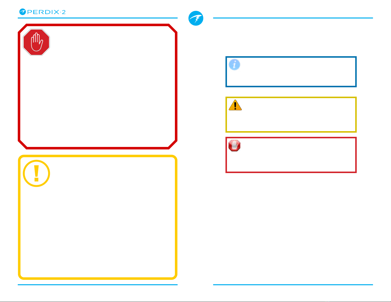
INFORMATION
Information boxes contain useful tips for
getting the most out of your Perdix 2�
CAUTION
Caution boxes contain important instructions
for operating your dive computer�
WARNING
Warning boxes contain critical information
that may affect your personal safety�
This computer has bugs. Although we haven’t found them all yet,
they are there. It is certain that there are things that this computer
does that either we didn’t think about, or planned for it to do
something different. Never risk your life on only one source of
information. Use a second computer or tables. If you choose to
make riskier dives, obtain the proper training and work up to them
slowly to gain experience.
This computer will fail. It is not whether it will fail but when it will
fail. Do not depend on it. Always have a plan for how to handle
failures. Automatic systems are no substitute for knowledge and
training.
No technology will keep you alive. Knowledge, skill, and practiced
procedures are your best defense (except for not doing the dive, of
course).
WARNING
This computer is capable of calculating deco stop requirements. These
calculations are at best a guess of real physiological decompression
requirements. Dives requiring staged decompression are substantially
more risky than dives that stay well within no-stop limits.
Diving with rebreathers and/or diving mixed gases and/or performing
staged decompression dives and/or diving in overhead environments
greatly increases the risk associated with scuba diving.
YOU REALLY ARE RISKING YOUR LIFE
WITH THIS ACTIVITY.
DANGER
Page 4 Doc. 13301-Tec-RevB (2022-05-25)
Technical Modes
Operating Instructions
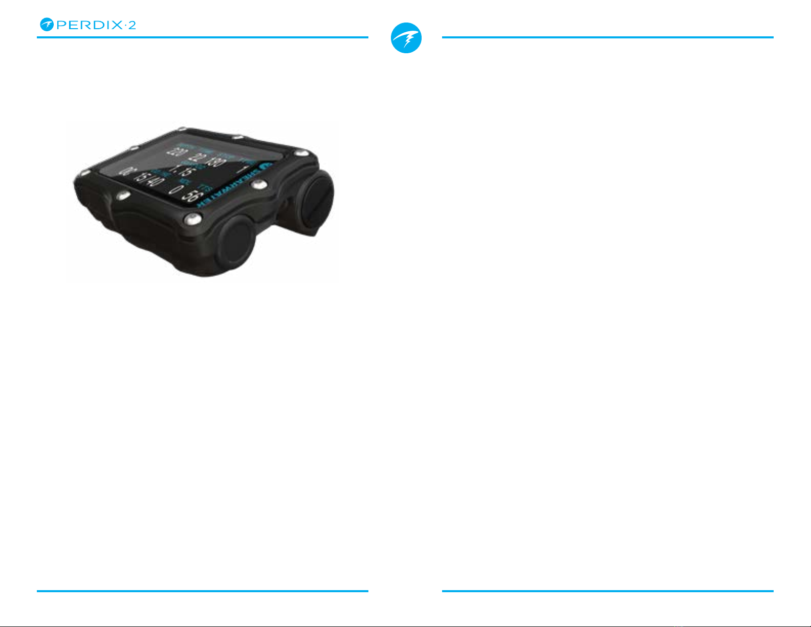
Features
• Full color 2�2” LCD display
• Rugged computer construction
• Titanium bezel
• User replaceable battery
• Customizable vibration alerts
• Programmable depth sampling rates
• Depth sensor calibrated to 130 msw
• Depth sensor function past 300 msw
• Crush pressure rating of 260 msw
• 6 independently configurable diving modes
• Simplified recreational modes (Air & Nitrox)
• 5 customizable gases in technical diving modes
• Any combination of Oxygen, Nitrogen and Helium
(Air, Nitrox,Trimix)
• Full decompression and CCR Support
• Bühlmann ZHL-16C with gradient factors standard
• Optional VPM-B and DCIEM decompression
models
• No lockout for violating deco stops
• CNS Tracking
• Gas Density Tracking
• Quick NDL and full decompression planner built in
• Simultaneous wireless pressure monitoring of up
to 4 cylinders
• Sidemount diving features
• Tilt compensated digital compass with multiple
display options
• Bluetooth Dive log uploading to Shearwater Cloud
• Free firmware updates
1. Introduction
The Shearwater Perdix 2 is an advanced dive computer
for all types of diving�
Please take the time to read this manual� Your safety
may depend on your ability to read and understand
your dive computer’s displays�
Diving involves risk and education is your best tool for
managing this risk�
Do not use this manual as a substitute for proper dive
training and never dive beyond your training� What you
don’t know can hurt you�

Page 5 Doc. 13301-Tec-RevB (2022-05-25)
Technical Modes
Operating Instructions
1.2. Modes Covered by this Manual
This manual provides operating instructions for the
Perdix 2 in the following technical operating modes:
• Open Circuit Technical (OC Tec)
• Closed Circuit / Bail Out (CC/BO)
• Gauge
The Shearwater Perdix 2 also has 3 modes specifically
designed for Open Circuit Recreational diving:
• Air
• Nitrox (up to 40% O2)
• 3 GasNx (up to 100% O2)
For detailed instructions on operation in recreational
modes, please see the Perdix 2 Recreational Modes
Manual.
Some features of the Perdix 2 only apply to certain
dive modes� If not otherwise indicated, features
described are applicable in all dive modes�
Read more about Mode Setup on page 63�
1.1. Notes on this manual
This manual provides operating instructions for the
Perdix 2 dive computer in technical operating modes
only�
This manual contains cross-references between
sections to make it easier to navigate�
Underlined text indicates the presence of a link to
another section�
Do not change any settings on your Perdix 2 without
understanding the consequence of the change. If
you are unsure, consult the appropriate section of the
manual for reference�
This manual is not a substitute for proper training�
Firmware Version: V91
This manual corresponds to firmware version V91�
Feature changes may have been made since this
release and might not be documented here�
Check the release notes on Shearwater.com for a
complete list of changes since the last release.

Page 6 Doc. 13301-Tec-RevB (2022-05-25)
Technical Modes
Operating Instructions
2. Basic Operation
2.1. Turning On
To turn the Perdix 2 on, press both buttons together�
Do Not Rely On The Auto-On Feature
This feature is supplied as a backup for
when you forget to turn on your Perdix 2�
Shearwater recommends turning your
computer on manually before each dive
to confirm proper operation and to
double check battery status and setup�
Auto-on
The Perdix 2 will automatically turn-on when
submerged underwater� This is based on pressure
increase and not on the presence of water� When
auto-on is activated, the Perdix 2 will enter the last
configured dive mode�
Auto-on Details
The Perdix 2 turns on automatically and enters dive
mode when the absolute pressure is greater than 1100
millibar (mbar)�
For reference, normal sea level pressure is 1013 mbar
and 1 mbar of pressure corresponds to approximately
1 cm (0�4”) of water� So, when at sea level, the Perdix
2 will automatically turn-on and enter dive mode
when about 0�9 m (3 ft) underwater�
If at higher altitude, then the Perdix 2 auto-on will
occur at a deeper depth� For example, when at 2000
m (6500 ft) altitude the atmospheric pressure is only
about 800 mbar� Therefore, at this altitude the Perdix
2 must be submerged underwater by 300 mbar to
reach an absolute pressure of 1100 mbar� This means
the auto-on occurs at about 3 m (10 ft) underwater
when at an altitude of 2000 m�
2.2. Customizable Splash Screen
After turning on, the Perdix 2 Splash Screen is
displayed for 2 seconds�
Customizable start up text can be added using the
Shearwater Cloud Desktop app�
The image itself can also be customized using the
Shearwater Cloud Desktop App�
Note that the computer will revert to the standard
splash screen on a firmware update� The custom
splash screen will then need to be reloaded�
See the section on Firmware Update and Log
Download on page 74 for details�

Page 7 Doc. 13301-Tec-RevB (2022-05-25)
Technical Modes
Operating Instructions
2.3. Buttons
Two titanium piezo-electric buttons are used to
change settings and view menus�
All Perdix 2 operations are simple single button
presses�
MENU (left)
button
Button Hints
When in a menu, button hints indicate the function of
each button:
In the example above, the hints tell us:
• Use MENU to change the brightness value
• Use SELECT to save the current value
Don’t worry about remembering all the button rules
below� Button hints make using the Perdix 2 easy�
SELECT (right)
button
SURFACE
hr
mn
15
Save
Brightness Med
Change
2
0
DEPTH
TIME
1.2
PPO2
MENU hint SELECT hint
MENU (Left) button
From main screen Brings up menu
In a menu Moves to the next menu item
Editing a setting Changes the setting’s value
SELECT (Left) button
From main screen Steps through info screens
In a menu Performs command or starts
editing
Editing a setting Saves the setting’s value
BOTH BUTTONS
When Perdix 2 is off pressing MENU and SELECT
at the same time will turn the Perdix 2 on� No other
operation requires pressing both buttons at the same
time�

Page 8 Doc. 13301-Tec-RevB (2022-05-25)
Technical Modes
Operating Instructions
The breathing mode
indicator in the bottom
left of the screen
shows which mode the
computer is currently
in�
OC Tec mode
is designed for
decompression diving�
This mode supports
helium and contains a
built in decompression
planner� TTS cannot
be removed from the
display�
CC/BO is designed for
use as an off-board
computer for a closed
circuit rebreather�
The current internal
setpoint being used
for decompression
calculations is always
displayed in the middle
of the display in this
mode�
Gauge mode converts
the Perdix 2 into a basic
bottom timer� Gauge
mode has a unique
layout�
Depth and dive time is
larger in Gauge mode�
Decompression tissues
are not tracked in this
mode�
2.4. Changing between Modes
By default the Perdix 2 is set to 3 GasNx Mode�
Recreational focused
modes can be
distinguished by the
large-font layout�
For directions on how
to use the recreational
focused modes on the
Perdix 2, see the Perdix
2 Recreational Modes
Manual.
This manual covers
operation in technical
diving modes� Switch to
one of these modes in
the mode setup menu�
See details on page
63�
Technical modes have
a more dense layout
and are capable
of displaying more
information on the
screen�
3:00
Air 21
m
.o23°C
10:55am
MAX
.
7
:
:
Mode OC Tec
Salinity EN13319
Next
Edit
Mode Setup
TIME
TTS
OC 21/00 12 3
O2/HE
NDL
PPO2
DEPTH
TIME
STOP
28.0
.80
4
TIME
TTS
CC 21/00 15 3
O2/HE
NDL
DEPTH
TIME
STOP
28.0
1.3
4
3 GasNX Mode
Mode Setup Menu
OC Tec Mode
CC/BO Mode
MAX
47
22
STOPWATCH
8:35
AM
AVG
22C
21:16
16:56
MAX
AVG
39
m
m
.8
m
.5
.0
Gauge Mode

Page 9 Doc. 13301-Tec-RevB (2022-05-25)
Technical Modes
Operating Instructions
3. Mounting Options
The Perdix 2 includes mounting points for either two
elastic straps or two bungee chords�
3.1. Elastic Straps
Install the elastic straps as shown in the image below�
The buckles feature a locking mechanism to prevent
them from inadvertently loosening� Press the tab to
allow the buckle to slide freely on the straps�
Strap width is 3/4” (19mm)�
3.2. Shock Cord
Bungee or shock cord can be installed in many ways
on the Perdix 2� The Perdix 2’s holes are sized for 3/16”
cord�
Shearwater recommends the knot shown below� This
knot has the nice feature of creating loops that stay
wide open while donning the Perdix 2 and the knots
will not pull free under high load�
Install straps and buckles as shown
When using bungee or shock cord, always create two
independent loops so that a single break will not result
in a lost dive computer�
1
2
34

Page 10 Doc. 13301-Tec-RevB (2022-05-25)
Technical Modes
Operating Instructions
4. Dive Interface
4.1. Default Dive Setup
The Perdix 2 comes pre-configured for recreational
diving� The default dive mode is 3 Gas Nitrox mode (3
GasNx)�
As a quick reference, a diagram of the default diving
display is shown below�
This manual is for technical dive modes only� Many
features of the above default display are shared by
the dive modes covered in this manual�
For directions on how to use Air, Nitrox or 3 GasNx
modes, see the Perdix 2 Recreational Modes Manual.
The next section lists all the dive modes available on
the Perdix 2� Change the Dive Mode from the Mode
Setup menu� See details on page 63
Default Dive Display -
3 GasNx mode
4.2. Dive Mode Differentiation
Each dive mode is designed to best suit a particular
type of diving�
Air
Designed for use during recreational, air only,
no-decompression diving activities�
• Air (21% oxygen) only, not switchable underwater
Nitrox (Single Gas)
Designed for use during recreational, Nitrox,
no-decompression diving activities�
• Single Gas Nitrox up to 40% oxygen
• No gas switching underwater
3 GasNx (Three Gas Mode)
Designed for introductory technical diving activities
including diving involving planned decompression�
• Three programmable gases
• Support for gas switching
• Nitrox up to 100%
OC Tec
Designed for open circuit technical diving activities
including planned decompression�
• Full Trimix
• No Safety stops
CC/BO
Designed for use with a closed circuit rebreather�
• Fast switching from closed circuit to open circuit
(BO) operating modes�
Gauge
Gauge Mode turns the Perdix 2 into a simple depth
and time display with a dedicated layout (bottom
timer)� See details on page 37�
• No tissue tracking
• No decompression information
Ascent Rate
No-Deco
Limit
Dive Time
Active Gas
3:00
Air 21
m
.o23°C
10:55am
MAX
.
7
:
:
Depth
Safety Stop
Nitrogen
Loading
Temperature
Time

Page 11 Doc. 13301-Tec-RevB (2022-05-25)
Technical Modes
Operating Instructions
4.3. Main Screen Layout
In OC Tec and CC/BO modes, the main screen shows
the most important information needed for technical
diving�
The Top and Bottom row content are reserved for the
most critical information required for technical diving�
The information displayed in these rows is fixed�
The Centre row contents can be configured to display
the data that the user feels is most important� In OC
Tec mode, the entire row is configurable� In CC/BO
mode, left and right positions can be configured, but
the current setpoint is always displayed in the center
position and cannot be removed�
See page 67 for Center Row configuration options�
Pressing the Select (right) button scrolls through
additional data in the bottom row, temporarily
obscuring this information� See the Info Screens
section on page 16 for more information�
The following section goes into detail about each
screen element�
TIME
TTS
OC 15/40 0 56
O2/HE
NDL
1.15
PPO2
67.0 22 39 1
DEPTH
TIME
STOP
}Top Row
Depth, Time &
Deco Stops
Center Row
Configurable
Bottom Row
Mode, Gas, NDL
& TTS
}
}
4.4. Detailed Descriptions
The Top Row
The top row shows depth, dive time, ascent rate,
decompression information and battery status�
Depth
Displayed in feet or meters�
In feet, depth displays with no decimal places� In meters,
depth displays with one decimal place up to 99�9m�
Note: If the depth shows a Flashing Red zero or shows a
depth at the surface, then the depth sensor needs service�
Ascent Rate Display
Shows how fast you are currently ascending�
1 arrow per 3 meters per minute (mpm) or 10 feet per
minute (fpm) of ascent rate�
Decompression calculations assume 10mpm (33fpm)
ascent rate�
WHITE when less than 9 mpm / 30 fpm
(1 to 3 arrows)
YELLOW when greater than 9 mpm /
30 fpm and less than 18 mpm / 60 fpm
(4 or 5 arrows)
FLASHING RED when greater than
18 mpm / 60 fpm (6 arrows)
TIME
67.0 22 39 1
DEPTH
TIME
STOP
in feet in meters
TIME
220 22 130 1
DEPTH
TIME
STOP
69.7
DEPTH
Page 12 Doc. 13301-Tec-RevB (2022-05-25)
Technical Modes
Operating Instructions
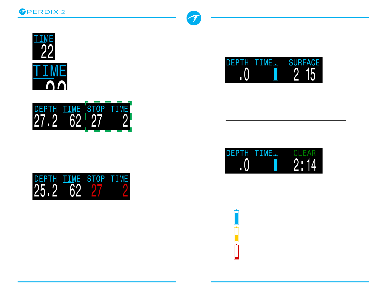
Dive Time
The first “TIME” item, on the left
of the top row, is the length of the
current dive in minutes�
Seconds display as a bar drawn
below the word “Time�” It takes 15
seconds to underline each character
in the word� The seconds bar is not
displayed when not diving�
Decompression Stop Depth and Time
22
TIME
22
TIME
BLUE when battery charge is OK
YELLOW when battery needs to
be replaced�
RED when battery must be
replaced immediately�
Stop at 27 meters for 2 minutes
TIME
25.2 62 27 2
DEPTH
TIME
STOP
Surface Interval
When on the surface, decompression stop depth
and time are replaced by a surface interval display
showing the hours and minutes since the end of your
last dive�
SURFACE
TTS
OC 21/00 0 0
O2/HE
NDL
.21
GasPO2
.0
DEPTH
TIME
hm
15
2
CLEAR
TTS
OC 21/00 0 0
O2/HE
NDL
.21
GasPO2
.0
DEPTH
TIME
2:14
TIME
27.2 62 27 2
DEPTH
TIME
STOP
The third item in the Top row, “Stop”, indicates the
next decompression stop depth in the current units
(feet or meters)� This is the shallowest depth to which
you can ascend� The last item on the right in the top
row, “time”, is how long in minutes to hold the stop�
Decompression Stop Violated
Decompression information will Flash Red if you
ascend shallower than the current stop�
By default the Perdix 2 uses a 3m (10ft) last deco stop
depth� You may perform your last deco stop deeper
if you wish - deco calculations will remain accurate� If
you choose to do this, depending on your breathing
gas, the predicted time-to-surface may be shorter
than the actual TTS since off-gassing may occur
slower than the algorithm expects� There is also an
option to set the last stop to 6m (20ft)�
2 hour and 15 minute surface interval
Above 4 days, the surface interval is displayed in days�
The surface interval is reset when the decompression
tissues are cleared� See the Decompression Tissue
Loading section on page 78 for more information�
Deco Clear Counter
When deco clears the STOP DEPTH and TIME are
replaced by a counter that begins counting up from 0�
Battery Icon
The default behavior is that the battery icon is shown
on the surface but disappears when diving� If low or
critical then the battery icon will appear while diving�
Page 13 Doc. 13301-Tec-RevB (2022-05-25)
Technical Modes
Operating Instructions
The Center Row
STOP
TTS
OC 15/40
O2/HE
NDL
DEPTH
TIME
MAX
m
PPO2
61.0
1.15
0
70
TIME
56
22 39 1
.7
SurGF
%
83
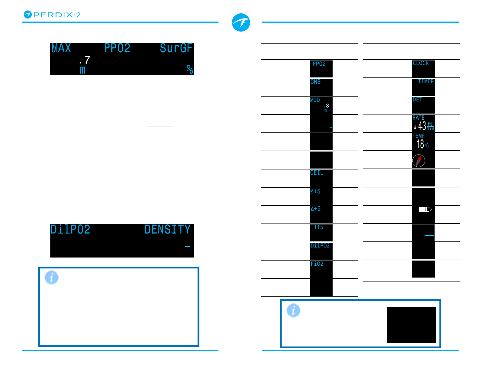
Home Screen Configuration Options
Option Info Display
PPO2
CNS %
MOD
Gas Density
GF99
Surface GF
Ceiling
@+5
Δ+5
Time To
Surface
Dil� PPO2
FiO2
Mini Display
Option Info Display
CLOCK
Timer
Dive End
Time
RATE
Temperature
Compass
Max Depth
Avg� Depth
Tank
Pressure
Surface Air
Consumption
Gas Time
Remaining
Redundant
Time
Remaining
STOP
TTS
OC 15/40
O2/HE
NDL
DEPTH
TIME
DilPO2
61.0
1.3
0
.71
TIME
56
22 39 1
DENSITY
DENSITY
44
g
L
In CC mode, PPO2 displays in Flashing Red
when less than 0�40 or greater than 1�6�
In OC Tech mode, PPO2 displays in Flashing Red
when less than 0�19 or greater than 1�65�
The above limits can be adjusted in the Adv�
Config 2 menu� See details on page 72
Default PPO2 Limits
Mini Displays for the left
and right custom slots can
each hold 3 data displays�
See details on page 23�
Mini Displays
TIME
TTS
OC 50/00 0 27
O2/HE
NDL
11
CEIL
13.2 36 12 2
DEPTH
TIME
STOP
GF9937
%
Δ+5 -4
MOD 22m
PO21.09
CNS 21%
SfGF
180
STOP
TTS
OC 15/40
O2/HE
NDL
DEPTH
TIME
Δ
Δ
+5
PPO2
61.0
1.15
0
+8
TIME
56
22 39 1
SurGF
%
83
STOP
TTS
OC 15/40
O2/HE
NDL
DEPTH
TIME
@+5
PPO2
61.0
1.15
0
20
TIME
56
22 39 1
SurGF
%
83
STOP
TTS
OC 15/40
O2/HE
NDL
DEPTH
TIME
CEIL
PPO2
61.0
1.15
0
17
TIME
56
22 39 1
SurGF
%
83
TIME
TTS
OC 21/00 0 3
O2/HE
NDL
24.0 22
DEPTH
TIME
STOP
SurGF
44
DENSITY
13
g
L
PPO2
71
%
TIME
TTS
OC 21/00 0 3
O2/HE
NDL
24.0 22
DEPTH
TIME
STOP
GF99
15
DENSITY
13
g
L
PPO2
71
%
TIME
TTS
OC 21/00 0 3
O2/HE
NDL
24.0 22
DEPTH
TIME
STOP
SurGF
44
DENSITY
13
g
L
PPO2
71
%
STOP
TTS
OC 15/40
O2/HE
NDL
DEPTH
TIME
MOD
m
PPO2
61.0
1.15
0
57
TIME
56
22 39 1
.3
SurGF
%
83
STOP
TTS
OC 15/40
O2/HE
NDL
DEPTH
TIME
CNS
PPO2
61.0
1.15
0
11
TIME
56
22 39 1
SurGF
%
83
STOP
TTS
OC 15/40
O2/HE
NDL
DEPTH
TIME
MAX
m
PPO2
61.0
1.15
0
70
TIME
56
22 39 1
.7
SurGF
%
83
All 3 locations configurable in OC Tec mode
In OC Tec mode, center row information is entirely
customizable� There are three configurable locations,
each of which can be populated independently�
A list of data options is given to the right� Center Row
Setup instructions can be found on page 67 �
The middle location of the center row displays gas
PPO2 by default� It has a smaller selection of data
options because it is slightly narrower than the left
and right slots�
For detailed descriptions of each screen element see
Info Screen Descriptions on page 17
In CC/BO mode the center slot is not configurable�
It always displays the currently selected rebreather
setpoint with no title text� The right and left slots can
still be customized�
STOP
TTS
OC 15/40
O2/HE
NDL
DEPTH
TIME
Δ
TTS
PPO2
61.0
1.15
0
15
TIME
56
22 39 1
SurGF
%
83
STOP
TTS
OC 15/40
O2/HE
NDL
DEPTH
TIME
Δ
DilPO2
PPO2
61.0
1.15
0
.99
TIME
56
22 39 1
SurGF
%
83
STOP
TTS
OC 15/40
O2/HE
NDL
DEPTH
TIME
Δ
FiO2
PPO2
61.0
1.15
0
.32
TIME
56
22 39 1
SurGF
%
83
TIME
TTS
OC 50/00 0 27
O2/HE
NDL
11
CEIL
13.2 36 12 2
DEPTH
TIME
STOP
GF99
37%
Δ+5 -4
MOD 22m
PO21.09
CNS 21%
SfGF
180
TIME
24.0 14
DEPTH
TIME
STOP
R
T1
175
B
A
37
GTR T1 SAC T1
1.5
Bar
min
3:00
57 21 3.13
m
.3
AVG
.7
:
:
MAX
m
AvgATM
.o
3:00
57 21 3.13
m
.3
AVG
.7
:
:
MAX
m
AvgATM
.o
3:00
319
.7
:
:
DATE
18C
TEMP
43
RATE
ft
min
STOP
TTS
OC 15/40
O2/HE
NDL
DEPTH
TIME
Δ
DET
PPO2
61.0
1.15
0
TIME
56
22 39 1
SurGF
%
831:31
STOP
TTS
OC 15/40
O2/HE
NDL
DEPTH
TIME
Δ
TIMER
PPO2
61.0
1.15
0
0:58
TIME
56
22 39 1
SurGF
%
83
STOP
TTS
OC 15/40
O2/HE
NDL
DEPTH
TIME
Δ
CLOCK
PPO2
61.0
1.15
0
12:58
TIME
56
22 39 1
SurGF
%
83
TIME
24.0 14
DEPTH
TIME
STOP
R
T1
175
B
A
37
GTR T1 SAC T1
1.5
Bar
min
TIME
24.0 14
DEPTH
TIME
STOP
R
T1
175
B
A
37
GTR T1 SAC T1
1.5
Bar
min
TIME
24.0 14
DEPTH
TIME
STOP
R
T1
175
B
A
16
RTR T1 SAC T1
1.5
Bar
min
Only 2 locations configurable in CC/BO mode
Page 14 Doc. 13301-Tec-RevB (2022-05-25)
Technical Modes
Operating Instructions
Current Circuit Mode
The active breathing mode configuration is displayed
on the far left of the bottom row� The options are:
The Bottom Row
The bottom row of technical dive modes displays the
current circuit mode, active gas, No Decompression
Limit (NDL), and Time To Surface(TTS)�
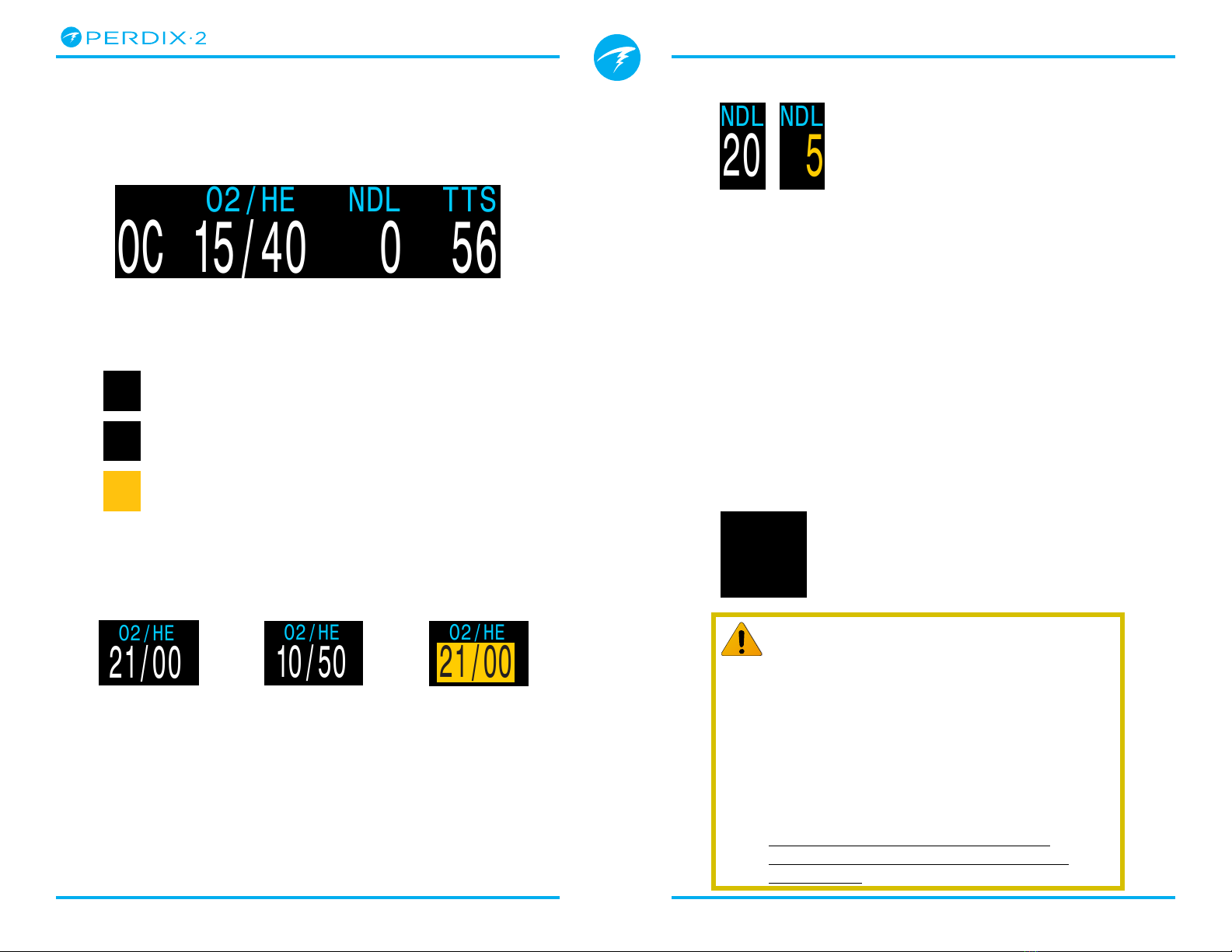
No Decompression Limit (NDL)
The time remaining, in minutes, at the
current depth until decompression
stops will be necessary� Displays in
Yellow when the NDL is less than the
low NDL limit (Default 5 minutes)�
NDL Replacement Options
Once NDL reaches 0 (i�e� deco stops needed), the
NDL display can be replaced by a small selection of
custom options to best utilize this space� See details
on page 69� The Mini option is described in more
detail on page 15�
The NDL replacement options are:
• Ceiling
• @+5
• Delta+5
• GF99
• SurGF
• Mini
Time To Surface (TTS)
The time-to-surface in minutes� This is
the current time to ascend to the surface
including the ascent plus all required
deco stops�
TTS
OC 15/40 0 56
O2/HE
NDL
CC
OC
BO
OC = Open circuit
CC = Closed circuit
BO = Bailout
(displays in Yellow to indicate bailout condition)
Active Gas
The current active gas shown as a percentage of
Oxygen and Helium� The remainder is assumed to be
Nitrogen�
20
NDL
5
NDL
Important!
All decompression information including
Deco Stops, NDL, and Time to surface are
predictions that assume:
• Ascent rate of 10mpm / 33fpm
• Decompression stops will be followed
• All programmed gases will be used as
appropriate
See the Decompression Information
Accuracy section on page 29 for more
information�
35
TTS
In open circuit mode, this is the breathing gas fraction�
In closed circuit mode, this is the active diluent gas�
The active gas displays in yellow when there is a
better gas available� Only turn on gases you plan to
use on your dive�
21/00
O2/HE
10/50
O2/HE
21/00
O2/HE
Air:
21% O2
79% N2
Trimix:
10% O2
50% He
79% N2
A better
deco gas is
available
Page 15 Doc. 13301-Tec-RevB (2022-05-25)
Technical Modes
Operating Instructions
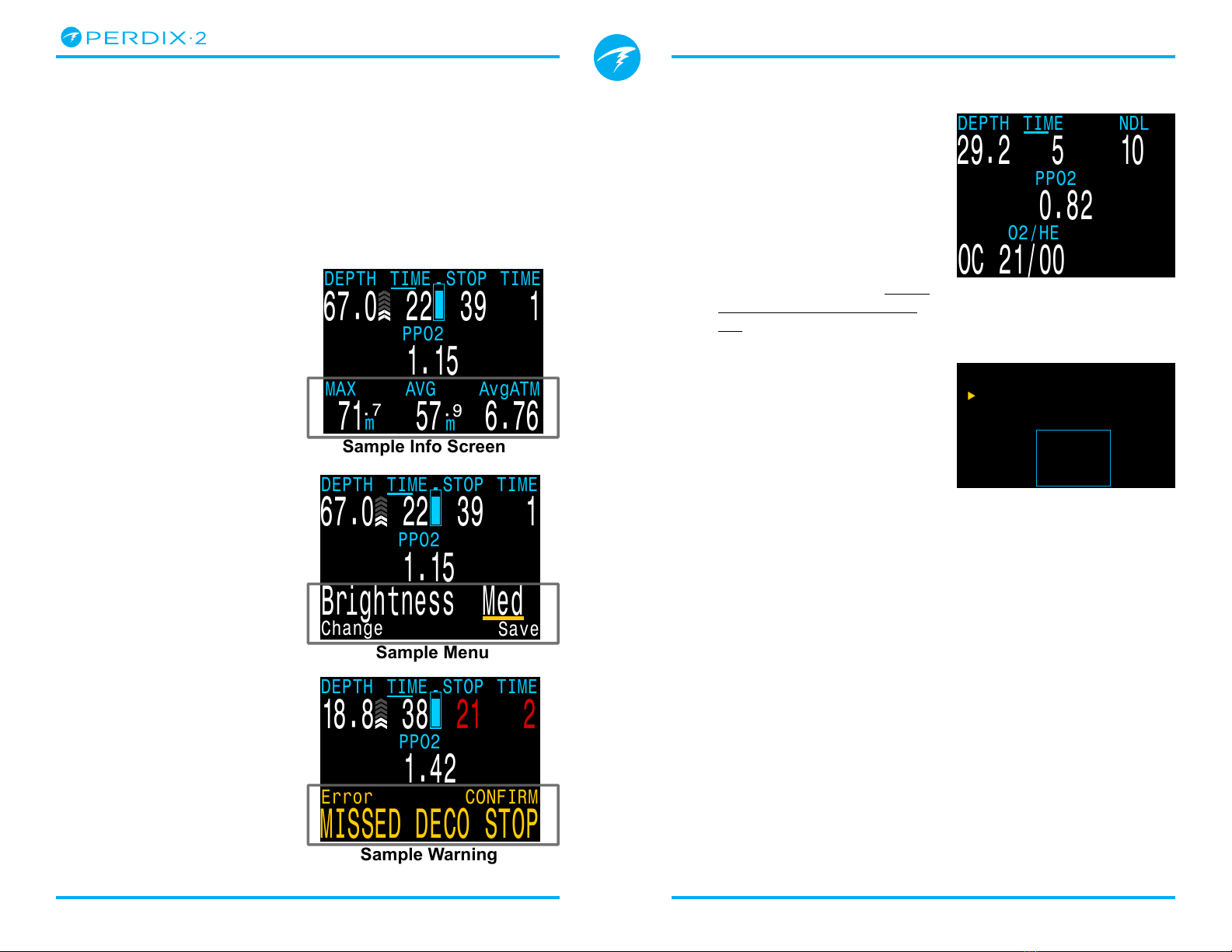
Additional Information
The bottom row is also used to show additional
information�
Only the bottom row changes during a dive, so critical
information contained on the Top and Center Rows is
always available�
Additional information that can be displayed on the
bottom row includes:
Info Screens:
Shows additional dive
information�
Press SELECT (right
button) to step through
info screens�
Menus:
Allows changing
settings�
Press MENU (left button)
to enter menus�
Warnings:
Provide important alerts�
Press any button to clear
a warning�
TIME
AvgATM
TIME
Save
Brightness Med
Change
67.0 22 39 1
DEPTH
TIME
STOP
TIME
MISSED DECO STOP
Error CONFIRM
18.8 38
21 2
DEPTH
TIME
STOP
Sample Info Screen
Sample Menu
Sample Warning
m
.7
MAX
AVG
57
PPO2
1.15
PPO2
1.42
PPO2
1.15
67.0 22 39 1
DEPTH
TIME
STOP
71 6.76
m
.9
Mini NDL Replacement Display
The Mini NDL replacement
display option reconfigures
the right side of the bottom
row to allow two additional
pieces of custom information
to be displayed�
The Mini NDL replacement
display can be configured
from System Setup > Deco
Setup described on page
64�
When the mini option is
selected the chosen custom
information is displayed at all
times� This is unlike the other
NDL replacement display
options which only appear
while the NDL is zero�
When in use, TTS is always
the first row option of this
mini display and cannot
be changed� The NDL is
relocated to the deco stop
and time information section
of the top row while there is
no decompression obligation�
NDL
OC 21/00
O2/HE
0.82
PPO2
DEPTH
TIME
DEN 5.2
TTS 3
SfGF
21%
29.2 5 10
Top
Center
TTS
DENSITY
Change Save
Bottom Surf GF
DEN 1.1
TTS 0
SfGF
0%
Mini Setup
NDL Replacement Mini
appearance
NDL Replacement Mini
setup menu�

Page 16 Doc. 13301-Tec-RevB (2022-05-25)
Technical Modes
Operating Instructions
4.5. Info Screens
Info screens provide more information than is
available on the main screen�
From the main screen, the SELECT (right) button
steps through info screens�
When all info screens have been viewed, pressing
SELECT again will return to the main screen�
Info screens also automatically time-out after 10
seconds, returning to the home screen� This prevents
active gas information from being hidden for an
extended period�
Note that the Compass, Tissues and AI Info screens do
not automatically time out when active�
Pressing the MENU (left) button will return to the
home screen at any time�
Although these screens are generally representative
of the Perdix 2 display, info screen content varies for
each mode� For example, decompression related info
screens are not available in gauge mode�
The next section gives detailed descriptions of the
data elements shown on the info screens�
3:00
12
52
-20/ 2
Δ+5
.7
:
:
DET @+5/TTS
:
Press the right (FUNC)
button, to step through
Info Screens
Return to Main Screen by:
•Pressing the left (MENU) button
•Stepping past last screen
•Waiting 10 Seconds (most screens)
3:00
Air 21
m
.o23°C
10:55am
MAX
.7
:
:
3:00
57 21 3.13
m
.3
AVG
.7
:
:
MAX
m
AvgATM
.o
3:00
20 12
GF
.7
:
:
TEMP
°C
CNS
30/70
3:00
15 62 0
SurGF
.7
:
:
GF99
%
CEIL
%
3:00
.7
:
:
TISSUES
3:00
4
.
12V
1.5V
.7
:
:
Alka
BATTERY
3:00
1020 1021
.7
:
:
PRESSURE mBar
SURF NOW
3:00
03-Mar-20 6 42
.7
:
:
DATE CLOCK
:
3:00
9F1F0432 20080BC
.7
:
:
SERIAL NO VERSION
SAFETY STOP
SURFACE
h
NDL
00
LAST DIVE
0
ft
N2
m
01
37
#1234
MAX m
0
h
52
m
38
s
.6
TIME
TTS
OC 21/00
O2/HE
NDL
PPO2
DEPTH
TIME
STOP
16.4
.55
33
240
9
4
TIME
NE
N
24
1.30
22.1 3
DEPTH
TIME
STOP
TIME
24.0 14
DEPTH
TIME
STOP
R
T2
163
B
A
R
T1
175
B
A
GTR 45
SM
SAC 1.5

Page 17 Doc. 13301-Tec-RevB (2022-05-25)
Technical Modes
Operating Instructions
4.6. Info Screen Descriptions
This section contains detailed descriptions of all info
screen and custom screen elements�
Last Dive Info
Maximum depth and dive time from the last dive� Only
available at the surface�
Air Integration
Only available if AI feature is turned on� The contents
of the AI info line will automatically adapt to the
current setup� Some examples include:
More information on AI features, limitations, and
displays can be found in the Air Integration (AI)
section on page 39�
SAFETY STOP
SURFACE
h
NDL
00
LAST DIVE
0
ft
N
2
m
01
37
#1234
MAX m
0
h
52
m
38
s
.6
T1 Only
T1 & GTR/SAC
T1 & T2
T1, T2 &
GTR/SAC
Compass
Marked headings appear in green while reciprocal
headings are shown in red� Green arrows point in the
direction of your mark when off course by 5˚ or more�
Compass info row will not time out and is only
available when compass feature is turned on�
See the Compass section on page 38 for more
information�
Maximum Depth
The maximum depth of the current
dive� When not diving, displays the
maximum depth of the last dive
Average Depth
Displays the average depth of the
current dive, updated once per
second� When not diving, displays
the average depth of the last dive�
Average Atmospheres
The average depth of the current
dive, measured in absolute
atmospheres (i�e� a value of 1�0 at
sea level)� When not diving, shows
the average of the last dive�
Temperature
The current temperature in degrees
Fahrenheit or degrees Celsius as
configured in Display Setup)
3:00
57 21 3.13
m
.3
AVG
.7
:
:
MAX
m
AvgATM
.o
T1, T2, T3,
& T4
TIME
24.0 14
DEPTH
TIME
STOP
R
T1
175
B
A
TIME
24.0 14
DEPTH
TIME
STOP
R
T1
175
B
A
37
GTR T1 SAC T1
1.5
Bar
min
TIME
24.0 14
DEPTH
TIME
STOP
R
T2
163
B
A
R
T1
175
B
A
TIME
24.0 14
DEPTH
TIME
STOP
R
T2
163
B
A
R
T1
175
B
A
GTR 45
SM
SAC 1.5
TIME
24.0 14
DEPTH
TIME
STOP
R
T2
163
B
A
R
T1
175
B
A
T3 197
T4 203
3:00
57 21 3.13
m
.3
AVG
.7
:
:
MAX
m
AvgATM
.o
3:00
57 21 3.13
m
.3
AVG
.7
:
:
MAX
m
AvgATM
.o
18C
TEMP
Page 18 Doc. 13301-Tec-RevB (2022-05-25)
Technical Modes
Operating Instructions
Maximum Operating Depth (MOD)
Only available as a custom display�
In OC mode MOD is the maximum
allowable depth of the current
breathing gas as determined by
PPO2 limits�
In CC mode, MOD is the maximum depth of the
diluent�
Displays in Flashing Red when exceeded�
Read more about PPO2 Limits on page 72
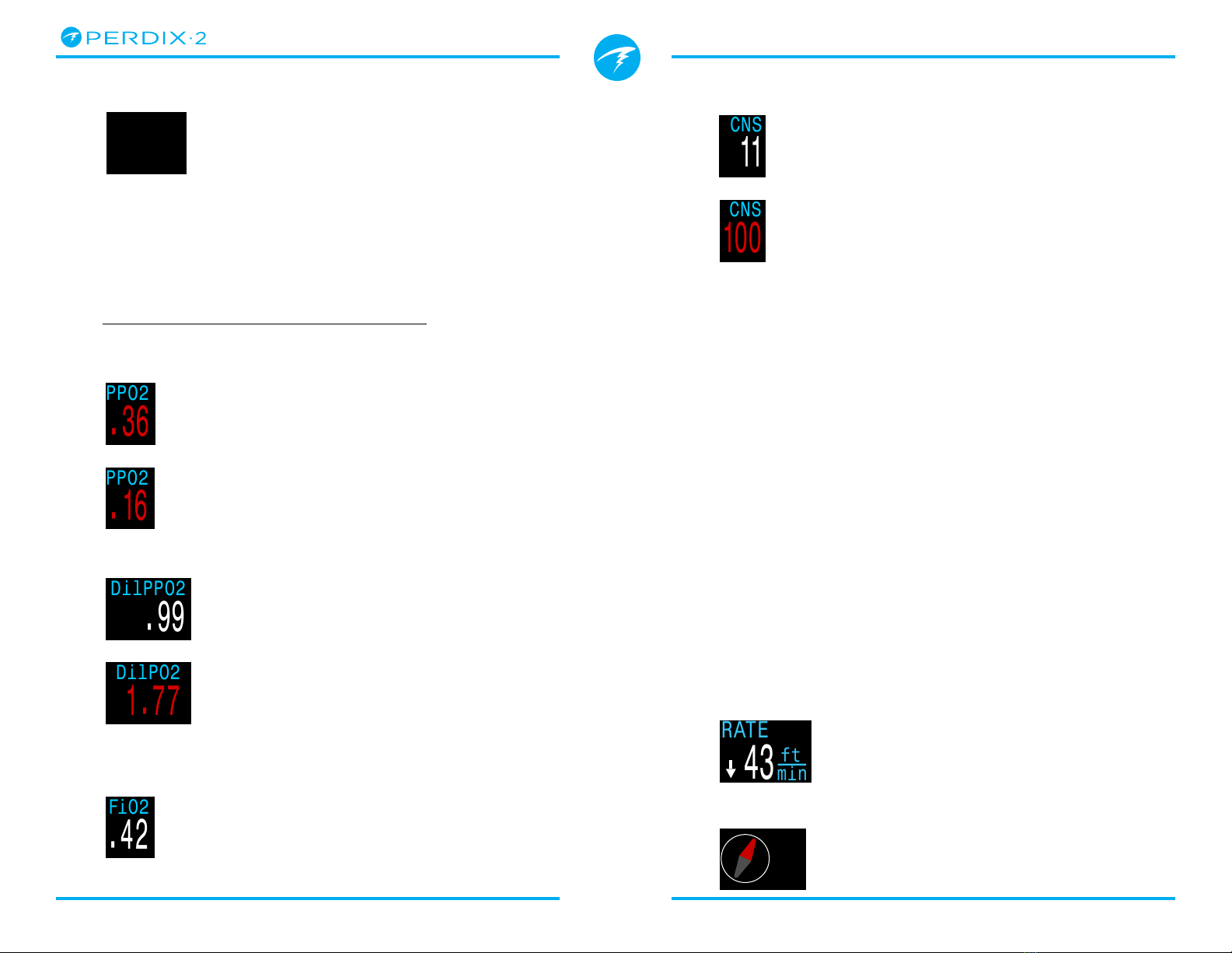
Partial Pressure of Oxygen (PPO2)
In CC mode, displays in Flashing
Red when less than 0�40 or greater
than 1�6 by default�
In OC mode, displays in Flashing
Red when less than 0�19 or greater
than 1�65 by default�
Diluent PPO2
Only displayed in CC mode�
Displays in Flashing Red when the
partial pressure of the diluent is less
than 0�19 or greater than 1�65�
When performing a manual diluent
flush, you can check this value to
see what the expected PPO2 will be
at the current depth�
Fraction of Inspired O2 (FiO2)
Only displayed in CC mode�
The fraction of the breathing gas
composed of O2�
This value is independent of
pressure�
3:00
57 21 3.13
m
.3
AVG
.7
:
:
MOD
m
AvgATM
.o
.36
PPO2
.16
PPO2
.99
DilPPO2
.42
FiO2
1.77
DilPO2
CNS Toxicity Percentage
Central Nervous System oxygen
toxicity loading percentage� Turns
Yellow when greater than 90%�
Turns Red when greater than 150%�
The CNS percentage is calculated
continuously, even when on the
surface and turned off� When deco
tissues are reset, the CNS will also
be reset�
The CNS value (short for Central Nervous System
Oxygen Toxicity) is a measure of how long you have
been exposed to elevated partial pressures of oxygen
(PPO2) as a percentage of a maximum allowable
exposure� As PPO2 goes up, the maximum allowable
exposure time goes down� The table we use is from
the NOAA Diving Manual (Fourth Edition)� The
computer linearly interpolates between these points
and extrapolates beyond them when necessary�
Above a PPO2 of 1�65 ATA, the CNS rate increases at a
fixed rate of 1% every 4 seconds�
During a dive the CNS never decreases� When back at
the surface, a half-life of elimination of 90 minutes is
used� So for example, if at the end of the dive the CNS
was 80%, then 90 minutes later it will be 40%� In 90
more minutes it will be 20%, etc� Typically after about
6 half-life times (9 hours), everything is back close to
equilibrium (0%)�
Rate
Numerical rate of ascent or descent�
Same colour rules as ascent indicator�
Available as a custom display only�
Mini Compass
A small compass that can be
displayed at all times� The red arrow
always points toward north�
Only available as a custom display�
11
CNS
100
CNS
3:00
319
.7
:
:
DATE
43
RATE
ft
min
Page 19 Doc. 13301-Tec-RevB (2022-05-25)
Technical Modes
Operating Instructions
SurfGF
The surfacing gradient
factor expected if the diver
instantaneously surfaced�
SurfGF colour is based on the current GF (GF99)� If
the current GF is greater than GF High, SurfGF will be
displayed in Yellow� If the current gradient factor is
greater than 100%, SurfGF will be displayed in Red.
Ceiling
The current decompression ceiling
not rounded to the next deeper
stop increment� (i�e� not a multiple
of 10ft or 3m)
@+5
“At plus 5” is the TTS if remaining
at the current depth for 5 more
minutes� This can be used as a
measure of how fast you are on-
gassing or off-gassing�
Δ+5
The predicted change in TTS if you
were to stay at the current depth
for 5 more minutes�
A positive “Delta plus 5” indicates that you are on-
gassing the leading tissue while a negative number
indicates that you are off-gassing the leading tissue�
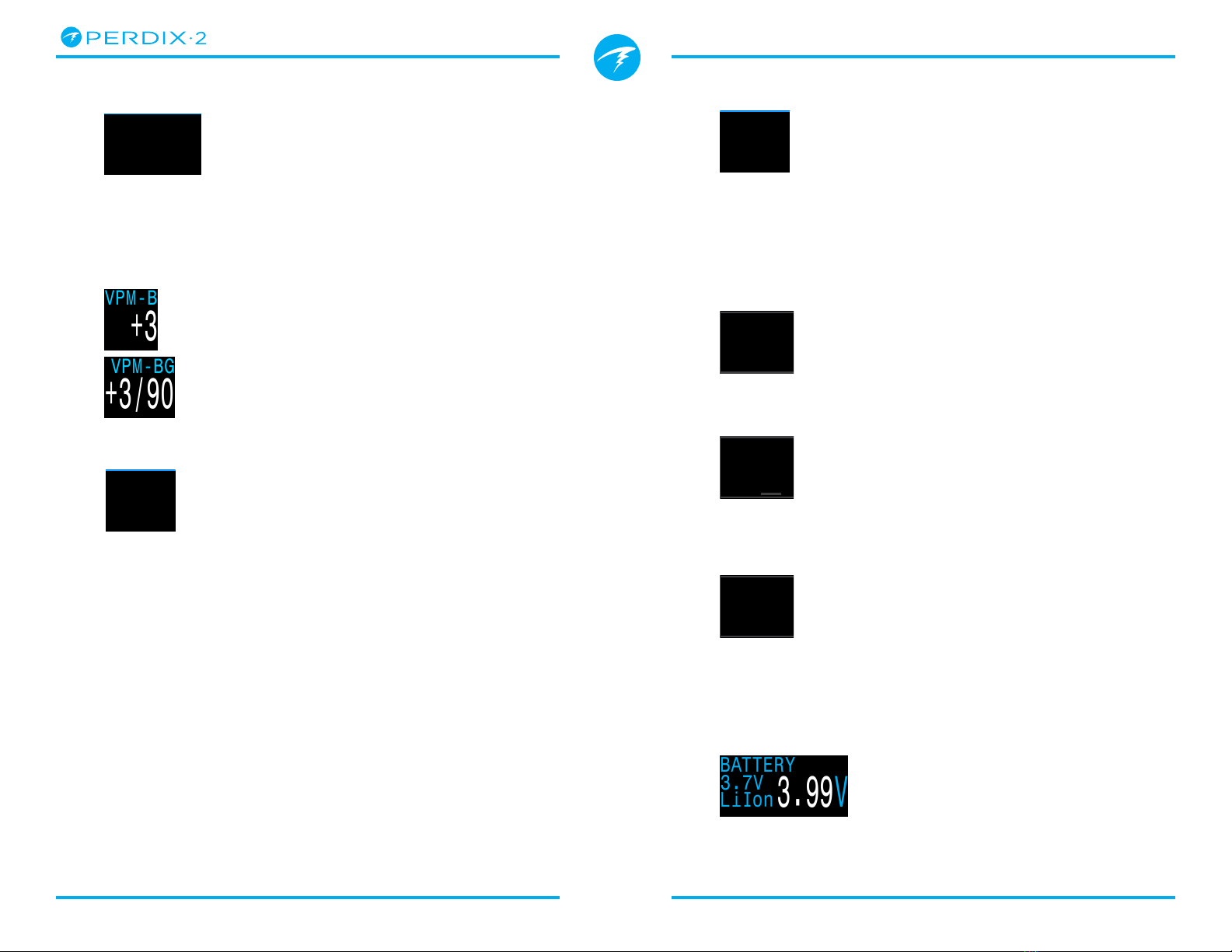
Battery
The Perdix 2’s battery voltage�
Displays in Yellow when the battery
is low and needs replacement�
Displays in Flashing Red when the
battery is critically low and must be
replaced as soon as possible� Also
shows battery type�
Gradient Factor
The deco conservatism value when
the deco model is set to GF� The low
and high gradient factors control
the conservatism of the Bühlmann
GF algorithm� See “Clearing up the
Confusion About Deep Stops” by
Erik Baker for more information�
VPM-B (and VPM-BG)
The deco conservatism value when
the deco model is set to VPM-B�
If the deco model is VPM-B/GFS,
also displays the gradient factor for
surfacing�
GF99
The current gradient factor as a
percentage (i�e� super-saturation
percent gradient)
0% means the leading tissue super-saturation is equal
to ambient pressure� Displays “On Gas” when tissue
tension is less than the inspired inert gas pressure�
100% means the leading tissue super-saturation is
equal to the original M-Value limit in the Bühlmann
ZHL-16C model�
GF99 is displayed in Yellow when the current gradient
factor modified M-Value (GF High) is exceeded�
GF99 is displayed in Red when 100% (un-modified
M-Value) is exceeded�
3:00
15 62 0
SurGF
.7
:
:
GF99
%
CEIL
%
3:00
20 12
GF
.7
:
:
TEMP
°C
CNS
30/70
3:00
15 62 0
SurGF
.7
:
:
GF99
%
CEIL
%
+3
VPM-B
+3/90
VPM-BG
mmin
Δ+5
+8
@+5
20
CEIL
8
SURFACE
mmin
Δ+5
+8
@+5
20
CEIL
26
SURFACE
mmin
Δ+5
+8
@+5
20
CEIL
26
SURFACE
3.99V
BATTERY
3.7V
LiIon
Page 20 Doc. 13301-Tec-RevB (2022-05-25)
Technical Modes
Operating Instructions
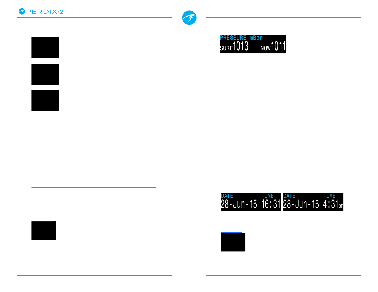
Pressure
The pressure in millibars� Two values are shown,
the surface (surf) pressure and the current (now)
pressure�
Note that typical pressure at sea level is 1013 millibar,
although it may vary with the weather (barometric
pressure)� For example, surface pressure may be as
low as 980 millibar in a low pressure system, or as
high as 1040 millibar in a high pressure system�
For this reason, the PPO2 displayed on the surface
may not exactly match the FO2 (fraction of O2),
although the displayed PPO2 is still correct�
The surface pressure is set based on the lowest
pressure the dive computer sees in the 10 minutes
prior to the start of a dive� Therefore, altitude is
automatically accounted for and no special altitude
setting is required�
Date and Time
In a 12 or 24 hour format� Time format can be changed
in the watch settings menu�
Timer
A simple stopwatch� The timer is
only available as a customizable
display� It is not available in the info
row�
Gas Density Display
The Gas Density display is only
available as a customizable display
and is not available in the info row�
For open circuit diving, the gas
density display turns yellow at 6�3
grams per liter� No other warnings
are generated�
For closed circuit diving, the gas
density display turns yellow at 5�2
grams per liter and red at 6�3 grams
per liter� No other warnings are
generated�
Gas density is an approximation based on the diluent
gas and loop PPO2�
You may be surprised at how shallow gas density
warning colors appear�
Read more about why we chose these levels starting
on page 66 here (recommendations on page 73):
Anthony, T.G and Mitchell, S.J. Respiratory physiology
of rebreatherdiving. In: Pollock NW, Sellers SH,
Godfrey JM, eds. Rebreathers and Scientific Diving.
Proceedings of NPS/NOAA/DAN/AAUS June 16-19,
2015 Workshop. Durham, NC; 2016.
Dive End Time (DET)
This is similar to TTS but is
expressed as a time of day�
The time of day at which you
can expect to surface if you
depart immediately, ascend at
10mpm or 33fpm, change gases
when prompted, and perform all
decompression stops as directed�
TIME
TTS
OC 21/00 0 3
O2/HE
NDL
24.0 22
DEPTH
TIME
STOP
SurGF
44
DENSITY
13
g
L
PPO2
71
%
1013
PRESSURE mBar
SURF
1011
NOW
28-Jun-15 16:31
DATE TIME
28-Jun-15 4:31pm
DATE TIME
3:00
03-Mar-20 6 42
.7
:
:
DATE DET
:
TIME
TTS
OC 21/00 0 3
O2/HE
NDL
24.0 22
DEPTH
TIME
STOP
SurGF
44
DENSITY
53
g
L
PPO2
71
%
TIME
TTS
OC 21/00 0 3
O2/HE
NDL
24.0 22
DEPTH
TIME
STOP
SurGF
44
DENSITY
64
g
L
PPO2
71
%
3:00
03-Mar-20 5 42
.7
:
:
DATE TIMER
:
Table of contents
Other Shearwater Diving Instrument manuals

Shearwater
Shearwater Peregrine User manual

Shearwater
Shearwater Perdix Instruction Manual

Shearwater
Shearwater Petrel 2 How to use

Shearwater
Shearwater Perdix User manual

Shearwater
Shearwater NERD 2 User manual

Shearwater
Shearwater Petrel Standalone User manual

Shearwater
Shearwater DCIEM User manual

Shearwater
Shearwater Petrel 3 User manual

Shearwater
Shearwater DiveCAN Petrel 1 User manual

Shearwater
Shearwater Perdix User manual


