Tritech MicronNav 200 User manual

MicronNav 200 Hardware Manual
0734-SOM-00002-01 Page 1 of 27
MicronNav 200 System
Hardware Manual
0734-SOM-00002-01

MicronNav 200 Hardware Manual
0734-SOM-00002-01 Page 2 of 27
© Tritech International Ltd
The copyright in this document is the property of Tritech International Ltd. The document is supplied by
Tritech International Ltd on the understanding that it may not be copied, used, or disclosed to others
except as authorised in writing by Tritech International Ltd.
Tritech International Ltd reserves the right to change, modify and update designs and specifications as
part of their ongoing product development programme. All product names are trademarks of their
respective companies.

MicronNav 200 Hardware Manual
0734-SOM-00002-01 Page 3 of 27
Table of Contents
Help & Support..................................................................................................................4
Warning Symbols ..............................................................................................................5
Introduction to Tritech USBL Technology ..........................................................................6
How does the Tritech USBL System Work? ......................................................................7
What makes up a Tritech MicronNav System?..................................................................8
Technical Specifications..................................................................................................10
Physical and Acoustic Details ......................................................................................10
MicronNav 200 Surface Hub........................................................................................11
USBL Dunking Transducer ..........................................................................................12
Battery Modem ............................................................................................................13
Micron Modem.............................................................................................................14
Electrical Connections and Pin-Outs ...............................................................................15
MicronNav 200 Hub.....................................................................................................15
Tritech Micron Connector.............................................................................................17
Using the MicronNav Hub................................................................................................18
System Installation ..........................................................................................................19
Using the MicronNav System with Tritech Sonars........................................................19
Reducing Magnetic Interference ..................................................................................19
Mounting the USBL Dunking Transducer.....................................................................20
Mounting the USBL Dunking Transducer to a Vessel...................................................22
System Mobilisation.........................................................................................................23
Pre-Dive ROV Installation Checklist.............................................................................23
Pre-Dive System Checklist...........................................................................................23
Operational Checklist...................................................................................................24
Troubleshooting...............................................................................................................25
MicronNav 200 Hardware Manual
0734-SOM-00002-01 Page 4 of 27
Help & Support
First please read this manual thoroughly (particularly the Troubleshooting section, if present).
If a warranty is applicable, further details can be found in the Warranty Statement, 0080- STF-
00139, available upon request.
Tritech International Ltd can be contacted as follows:
Mail
Tritech International Ltd
Peregrine Road
Westhill Business Park
Westhill, Aberdeenshire
AB32 6JL, UK
Telephone
+44(0)1224 744 111
Email
tritech-support@moog.com
Website
www.moog.com/tritech
Prior to contacting Tritech International Ltd please ensure that the following is available:
1. The Serial Numbers of the product and any Tritech International Ltd equipment connected
directly or indirectly to it.
2. Software or firmware revision numbers
3. A clear fault description
4. Details of any remedial action implemented
Contamination
If the product has been used in a contaminated or hazardous environment
you must de-contaminate the product and report any hazards prior to
returning the unit for repair. Under no circumstances should a product be
returned that is contaminated with radioactive material.
The name of the organisation which purchased the system is held on record at Tritech
International Ltd and details of new software or hardware packages will be announced at
regular intervals. This manual may not detail every aspect of operation and for the latest
revision of the manual please refer to www.moog.com/tritech
Tritech International Ltd can only undertake to provide software support of systems loaded
with the software in accordance with the instructions given in this manual. Tritech cannot
guarantee compatibility with or provide support for any other software packages used.

MicronNav 200 Hardware Manual
0734-SOM-00002-01 Page 5 of 27
Warning Symbols
Throughout this manual the following symbols may be used where applicable to denote any
particular hazards or areas which should be given special attention:
Note
This symbol highlights anything which would be of particular interest to the
reader or provides extra information outside of the current topic.
Important
When this is shown there is potential to cause harm to the device due to
static discharge. The components should not be handled without
appropriate protection to prevent such a discharge occurring.
Caution
This highlights areas where extra care is needed to ensure that certain
delicate components are not damaged.
Warning
DANGER OF INJURY TO SELF OR OTHERS
Where this symbol is present there is a serious risk of injury or loss of life.
Care should be taken to follow the instructions correctly and also conduct a
separate Risk Assessment prior to commencing work

MicronNav 200 Hardware Manual
0734-SOM-00002-01 Page 6 of 27
Introduction to Tritech USBL Technology
The MicronNav 200 system is the latest
generation of Ultra Short Base Line
(USBL) positioning system from Tritech.
The system is designed for small vehicles
and diver supporting applications.
The system benefits from a number of
new features including data transfer
interleaved with USBL positioning,
smaller, more accurate USBL Dunking
Transducer and compatibility with the
new Micron Battery Modem.
The system comprises a subsea Micron Modem or Battery Micron Modem, a surface USBL
transducer with integral magnetic compass and pitch/roll sensors, a surface MicronNav 200
interface hub and bespoke operating software under control of a topside PC/laptop.
The MicronNav 200 uses spread spectrum acoustic technology. This provides a robust
method for communication between the dunking transducers and the vehicle Micron
Modem/Micron Battery Modem.
The USBL Dunking Transducer can provide 180degree hemispherical coverage below the
transducer, which allows vehicle tracking in very shallow water. Omni-directional coverage is
provided by the Micron Modem and Micron Battery Modem.
The Micron Modem is a stand-alone device which either responds to acoustic interrogation
from the USBL Dunking Transducer (Transponder mode) or is triggered by RS232 / RS485
(responder mode) through the main port. The Responder trigger can come either from the
auxiliary port on a Tritech Micron Sonar, or directly from the MicronNav 200 interface hub.
Both the USBL Dunking Transducer and the Micron Modem/Micron Battery Modem can be
commanded to switch from positioning mode to data transfer mode, allowing the same
hardware to be used to establish an underwater acoustic communications link.
MicronNav 200 Hardware Manual
0734-SOM-00002-01 Page 7 of 27
How does the Tritech USBL System Work?
The quality of acoustic data transmission in water using conventional single frequency
systems suffers considerably from multi-path phenomena. Sound transmitted from the
sending modem arrives at the receiving unit via the direct path, and via a series of secondary
paths, due to reflections from the sea surface and sea bottom. This can often result in the loss
or corruption of transmitted data. In addition, conventional systems have poor immunity to the
continuously varying background sea noise (such as wave noise).
Tritech Spread Spectrum technology however does not concentrate the acoustic energy in
one waveband but produces a transmission which is linearly varied between 20 kHz and 28
kHz (known as a CHIRP waveform). By correlating the received signals with the CHIRP
waveform, it is possible to achieve superior performance in challenging multi-path
environments. In addition, identification of a unique transmission signature allows signals to
be detected in extremelynoisy conditions, to the extent that communication is successful even
when the signal to noise ratio is as low as -6dB. This means that data streams can be
successfully detected which are considerably below the background noise level.
Transmission Characteristics
Transmission characteristics are depended on a variety of operating conditions which can
significantly reduce operating range:
acoustically reflecting surfaces within the operating environment
etween two communicating
Modems
MicronNav 200 Hardware Manual
0734-SOM-00002-01 Page 8 of 27
What makes up a Tritech MicronNav System?
The standard system comprises of the following equipment:
Part Number
Description
Image
Quantity
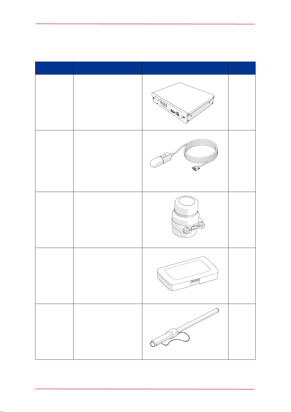
S11175
MicronNav 200 Hub
This is the surface interface for
the system and is connected to
the computer / laptop via a USB
cable
1
S11950 10M
(Standard
connector)
[other connector options
and lengths are available]
USBL Dunking
Transducer
This is the subsea interface for
the system, responsible for
communicating acoustically with
the modems and contains an
AHRS (Attitude and heading
reference system) sensor
1
S11960
Micron Modem
A standard system includes a
single modem. More can be
purchased as necessary
1
S08155
MicronNav Connector
Kit
This includes solder bucket
connectors for the D type and
DIN connectors used on the
MicronNav 200 Hub and a USB
A-B cable
1
S12639
0.5 Metre Carbon Fibre
Mounting Pole
1

MicronNav 200 Hardware Manual
0734-SOM-00002-01 Page 9 of 27
Additional Equipment
Part Number
Description
Image
Quantity
S11932
Battery Modem
This has all the same features
that a normal modem has, but
with the added convenience of
an internal battery. This is not
part of the standard system and
can be purchased separately.
The Modem and Battery modem
can be configured to work as a
Legacy modem operating as
either a (USBL or Data modem)
OR combining the two to provide
both USBL positioning and Data
transmission
1
S11992
6 pin Din Connector to
Micron Connector
(2 metre)
This cableis wired forboth power
and communications and allows
for configuration of micron
devices such as modem and
sonar. This is not standard
equipment and may be
purchased separately.
1
S12750
Reach & Rescue Pole
Adapter Assembly
Allows the USBL dunking
transducer to be mounted on the
end of the reach and rescue
pole
1
MicronNav 200 Hardware Manual
0734-SOM-00002-01 Page 10 of 27
Technical Specifications
Physical and Acoustic Details
System
Positioning technology
Ultra Short Baseline (USBL)
Frequency band
20 28kHz
Data rate
40bits/s or 100bits/s (spread spectrum)
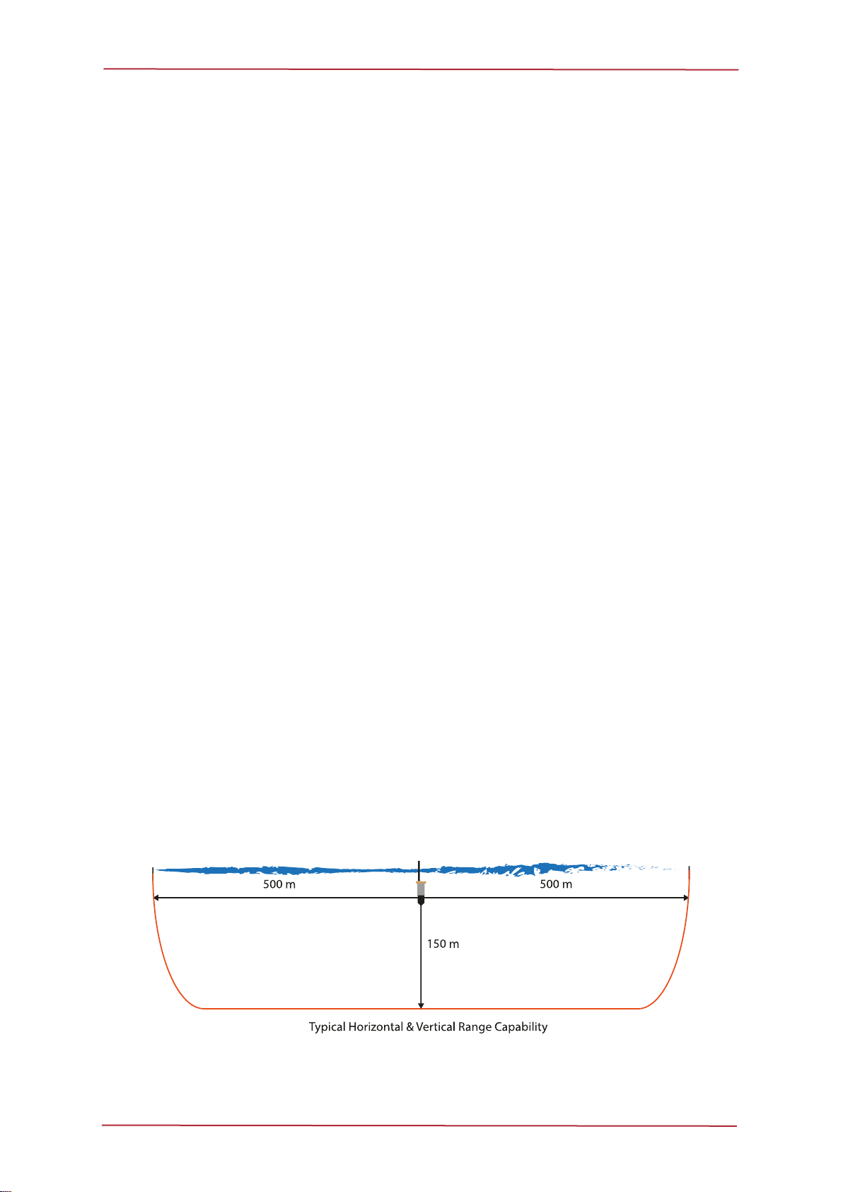
Tracking range *
500m Horizontal, 150m Vertical
Range accuracy **
±0.2m
Bearing accuracy
1° RMS (determined by USBL integrated heading sensor)
Pitch & Roll accuracy
0.2° Static / 0.5° Dynamic (typical)
Targets tracked
1 Responder or up to 254 Transponders
Doppler tolerance
±5m/s
*Range is dependent on operating conditions.
** ±2% of 10m slant, ±0.2% of 100m slant, ±0.04% of 500m slant - assumes correct speed of sound.
MicronNav 200 Hardware Manual
0734-SOM-00002-01 Page 11 of 27
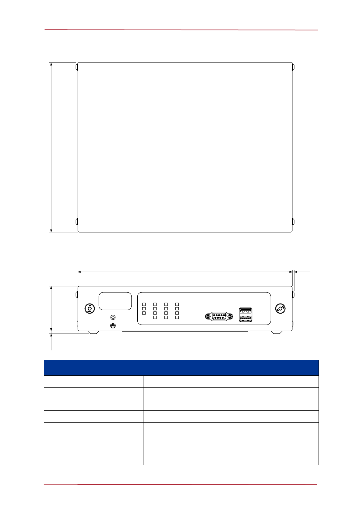
MicronNav 200 Surface Hub
MicronNav 200 Surface Hub
Power requirement (AC or DC)
90-264 VAC (47-63Hz) or 15-36 VDC
Power consumption
8.5W from either source (with no external load)
Output voltage
33V (when on AC Supply), 31.5V (when on DC supply)
Dimensions
232 x 185 x 52mm (width, depth, height)
Weight
1.4kg
Material
Stainless Steel housing with Anodised Aluminium front
fascia
Temperature rating
5° to 35°C (operational), -20° to 50°C (storage)
MicronNav 200 Hardware Manual
0734-SOM-00002-01 Page 12 of 27
USBL Dunking Transducer
USBL Transducer
Transmit source level
173dB re. 1µPa at 1m
Deck cable length
10m standard (20m, 50m options)
Depth rating
30m
Dimensions
75 x 250mm (diameter, length)
Weight in air
1.0kg
Weight in water
0.1kg
Temperature rating
-10° to 35°C (operational), -20° to 50°C (storage)
MicronNav 200 Hardware Manual
0734-SOM-00002-01 Page 13 of 27
Battery Modem

MicronNav 200 Hardware Manual
0734-SOM-00002-01 Page 14 of 27
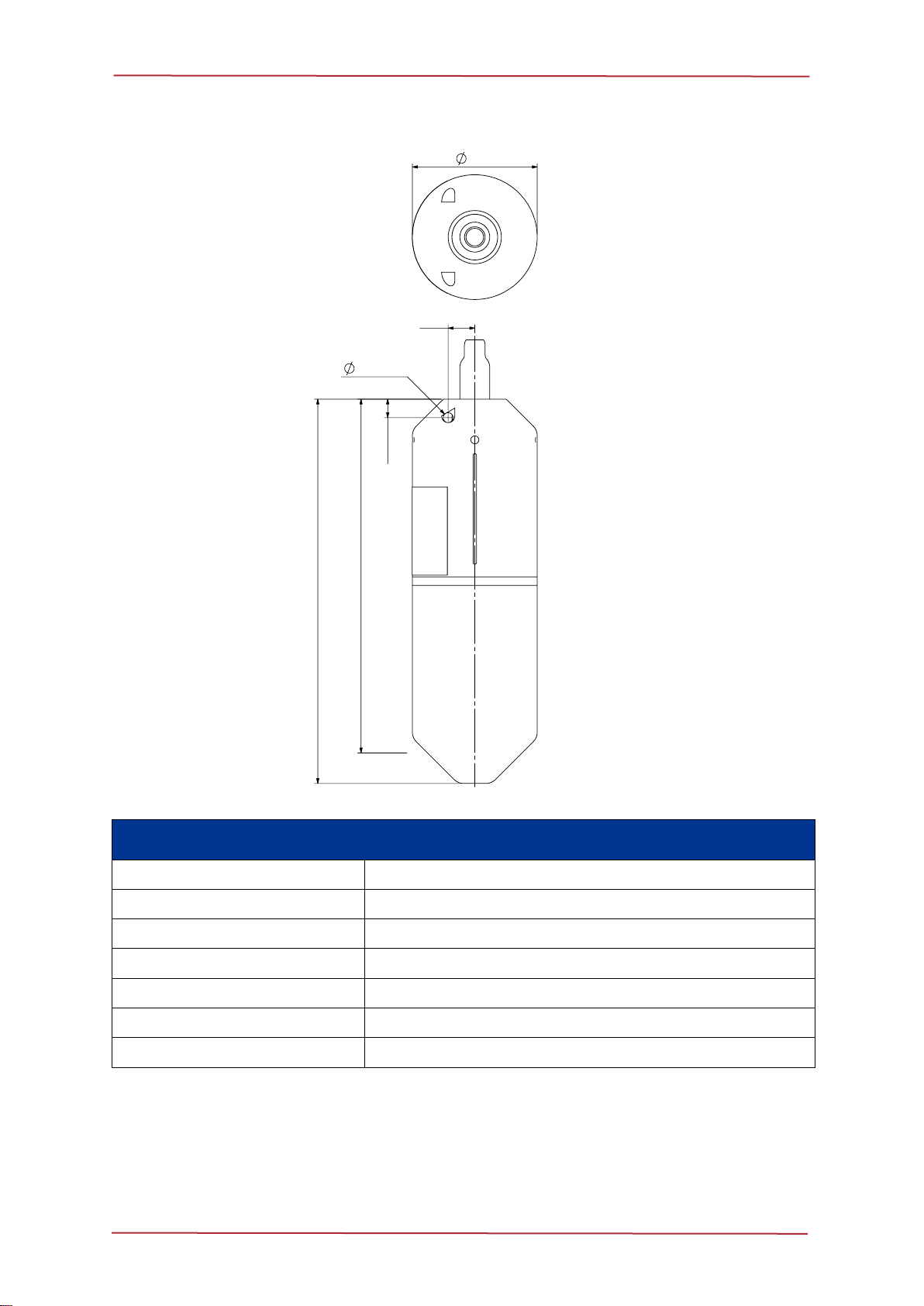
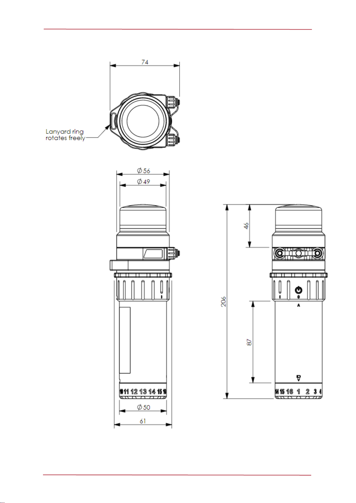
Micron Modem
Modem/Transponder/Responder
Micron Modem
Micron Battery Modem
Beam pattern
+/-90°, Omni-directional
Transmitter source
Communications protocol
RS232 or RS485 (internally set)
Depth rating
750m
Power consumption
3.5W transmitting
0.28W receiving
3.5W transmitting
0.05W receiving
Dimensions
56 x 77mm (depth,
height)
56 x 206mm (depth,
height)
Weight in air
0.24kg
0.89kg
Weight in water
0.08kg
0.45kg
AC Charger
N/A
90 -264VAC 47- 63Hz,
18W charging
Temperature rating *
-10° to 35°C (operational), -20° to 50°C (storage)
* Battery Modem operational temperature limited to no less than 10°C during charging or while on
external power.
MicronNav 200 Hardware Manual
0734-SOM-00002-01 Page 15 of 27
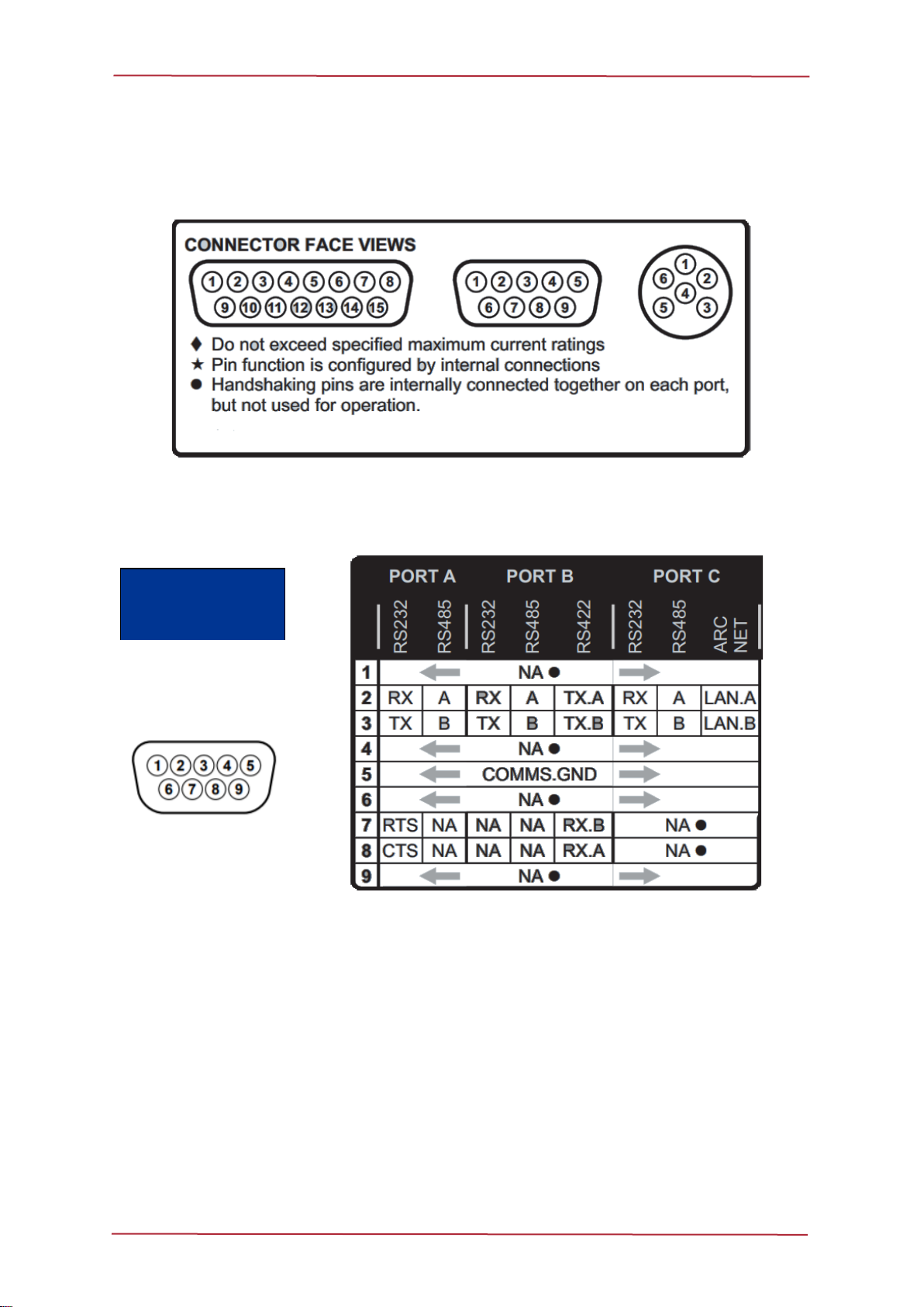
Electrical Connections and Pin-Outs
MicronNav 200 Hub
Ports A-C Electrical Connection
DE-9
Connector Face
View

MicronNav 200 Hardware Manual
0734-SOM-00002-01 Page 16 of 27
Port D Electrical Connection
Port D socket should be used with a DIN-45322 (6 pin) plug and should be wired as follows:
Connector
Face View
AIF (ARCNET) Port Electrical Connection
DA-15 AIF (ARCNET) connector, and should be wired as follows:
ARCNET
Connector
Face View
Note:
The voltage on pin 9 is selectable via an internal jumper, the factory default
is 33V / 31.5V.

MicronNav 200 Hardware Manual
0734-SOM-00002-01 Page 17 of 27
Tritech Micron Connector
A Tritech Micron tail (Part Number S05975) is supplied in 1 and 2 metre lengths and should
be wired as follows:
Connector Face View
PIN
Wire Colour
Function
1
Yellow
RS485 A
RS232 TX
2
Blue
RS485 B
RS232 RX
3
Red
DC +
4
Black
DC ground
5
Green
RS232 ground
6
Cable Sheath
earth
Caution
The Micron series connector is not wet mateable and direct exposure to
water when the unit is powered will cause damage. Care should be taken
when wiring the Micron Connector whip to the vehicle, as applying power to
the Communication lines could damage the electronic equipment.
Micron Connector Installation Precautions:
•
the blanking-plug provided, when not in use.
•Care should be taken when mating the connector, with either a plug or a blanking-plug,
to ensure both mating ends are clean and dry.
•Special attention should be given to checking the O-ring for dirt. The O-ring is located
under the lock-ring on both the plug and the blanking plug.
•The connector lock-ring needs only to be finger tight. The use of any tools to tighten
the lock-ring further is not necessary and could result in damage to the connector.

MicronNav 200 Hardware Manual
0734-SOM-00002-01 Page 18 of 27
Using the MicronNav Hub
Checking the MicronNav Hub Status
The MicronNav Hub has been designed to act as an interface device between the surface
control computer, USBL Dunking Transducer and connected subsea equipment. As such,
during normal operation there is little to no onscreen notification of the MicronNav Hub status.
The main means of checking the MicronNav Hub status are:
Genesis Software Application
If an additional device is added, or the configuration of the system has to be changed then the
front panel of the NavHub can be used as a primary diagnostic tool as it displays the
communications for each port, as well as the activity currently active on it.
The top row ofLEDs indicates the communication activitythat is currentlytaking place on each
port. A RED flash indicates communication from a device has been detected. A GREEN flash
indicates communication from the NavHub has been detected. This can provide a visual aid
in determining the status of equipment prior to any service work.
The next four rows of LEDs are used to indicate the communications protocol setup of each
port. All four ports are capable of communicating on RS232 and RS485, but only certain ports
are capable of communicating on ARCNET or RS422.
When Ports C and D are setup as ARCNET, the ports are electrically linked
to the 15-way ARCNET port at the rear of the MicronNav Hub.
When changes are made to the configuration of the MicronNav Hub, all the
LEDs will flash before the new configuration is displayed. During the
reconfiguration process all communication to connected devices will be
temporarily disrupted.
Protocol
Port A
Port B
Port C
Port D
RS232
Y
Y
Y
Y
RS485
Y
Y
Y
Y
RS422
N
Y
N
N
ARCNET
N
N
Y
Y

MicronNav 200 Hardware Manual
0734-SOM-00002-01 Page 19 of 27
System Installation
Using the MicronNav System with Tritech Sonars
It is possible to operate the MicronNav with other Tritech Sonars in the same way as that
detailed for the MKII/MKIII Micron. The following list provides details on MicronNav
compatibility with the other Tritech Sonars:
Caution
The Micron Modem has a power range of between 12- 48 Volts and care
should be taken not to exceed this.
Micron DST Sonar
This sonar requires a dual micron interconnect cable (Part Number S06372), and is available
in 0.5 metre, 1 metre and 2 metre lengths. This type of sonar supports both Transponder and
Responder modes of the Micron Modem.
Super SeaPrince Sonar/ Super SeaKing Sonar
The Super SeaPrince DST and the Super SeaKing DST Sonars, require the same Micron
Standard to Tritech Connector Right Angle (R/A) cable (Part Number S09819 0.5M). This
type of sonar supports both Transponder and Responder modes of the Micron Modem.
Gemini Multibeam Sonars
Transponder Mode is the only mode supported with the Gemini family of Multibeam sonars,
as it only requires power. This is fed from the sonars Aux port and will require special cabling,
please contact Tritech International Ltd. for more information.
Reducing Magnetic Interference
The MicronNav 200 software manual, contains instructions for the AHRS calibration
procedure. This calibration counteracts potential environmental magnetic interference which
could potentially affect the compass readings.
MicronNav 200 Hardware Manual
0734-SOM-00002-01 Page 20 of 27
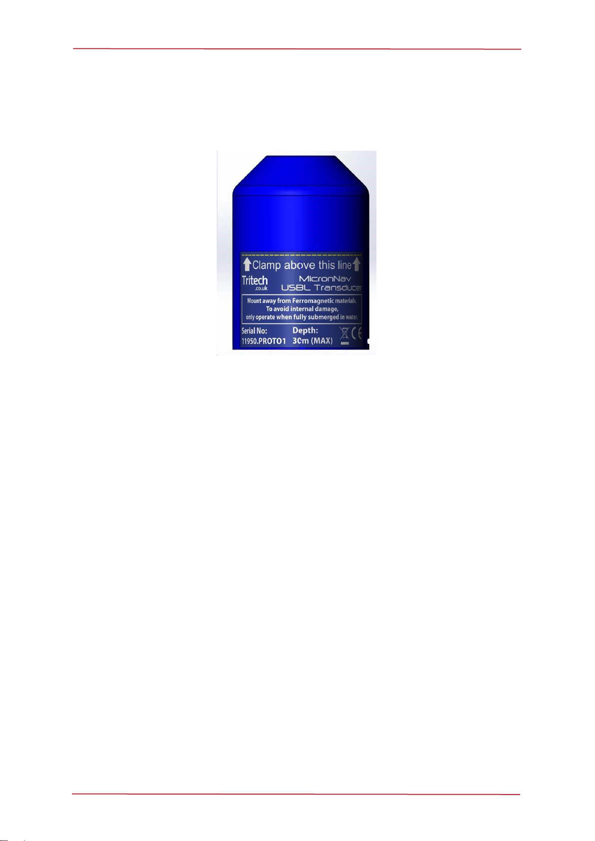
Mounting the USBL Dunking Transducer
The USBL Dunking Transducer may be secured with a 75mm diameter clamping mechanism,
placed above the line shown on the Product label as below.
The Clamping Point for the USBL Dunking Transducer.
Positioning the USBL Dunking Transducer
The yellow line on the top of the USBL Dunking Transducer, indicates the front of the
transducer head as can be seen in the illustration below. This should be positioned facing in
the required forward position to the fixed platform, to ensure correct representation on the PPI
display. When mounting on a vessel this should be pointed towards the bow.
The USBL Dunking Transducer should be mounted at least 2-3 metres away from the side
wall of a Fixed Platform or Dockside and if possible the hull of a vessel.
This manual suits for next models
1
Table of contents


