Tritech T4 Airless Sprayer User manual

TriTech.
T4 Airless Sprayer.
Aristospray (Ireland) Ltd
2b Stephenstown Industrial Park
Balbriggan
County Dublin
Ireland
K32 KV26
Email sales@aristospray.com
Web www.tritechairless.com
Phone
UK 01895 276751
Ireland 01 690 3162
International + 353 1690 3162
2b:creative - 028 9266 9888
TriTechAirless
Aristospray@Aristospray
USER
MANUAL

599-800
T4 STAND COMPLETE 120V
599-801
T4 STAND PUMP ONLY 120V
599-810
T4 STAND COMPLETE 240V
599-811
T4 STAND PUMP ONLY 240V
599-802
T4 HOPPER COMPLETE 120V
599-803
T4 HOPPER PUMP ONLY 120V
599-812
T4 HOPPER COMPLETE 240V
599-813
T4 HOPPER PUMP ONLY 240V
599-804
T4 HIGH CART COMPLETE 120V
599-805
T4 HIGH CART PUMP ONLY 120V
599-814
T4 HIGH CART COMPLETE 240V
599-815
T4 HIGH CART PUMP ONLY 240V
599-806
T4 LOW CART COMPLETE 120V
599-807
T4 LOW CART PUMP ONLY 120V
599-816
T4 LOW CART COMPLETE 240V
599-817
T4 LOW CART PUMP ONLY 240V
503-150
T360 AIRLESS SPRAY GUN
200-517
T93R AIRLESS TIP
200-999
T93R AIRLESS GUARD
400-114
50’ ¼” AIRLESS HOSE
WEEE Compliance
Statement
The mark shown to the right is in compliance with the Waste Electrical
and Electronic Equipment Directive 2002/96/EC (WEEE).
The mark indicates the requirement NOT to dispose of the equipment as
unsorted municipal waste, but use the return and collection systems according
to local law. Users should contact their supplier and check the terms and conditions
of the purchase contract. When purchased directly from TriTech Industries, or a
TriTech Industries Distributor you may contact technical support for disposal
arrangements.
RoHS Compliance Statement
TriTech Industries products are designed to meet Reduction of Hazardous Substance Directive 2011/65/EU
8June2011, the product manufactured by TriTech Industries do not contain materials that exceed thresholds for
cadmium, mercury, hexavalent chromium, Polybrominated diphenyl ethers (PBDEs) or other regulated substances.
Safety Compliance Statement
Tritech Industries product are certified meeting UL 1450 Issued: 2010/05/05 Ed: 4 Rev: 2013/11/01 Motor-
Operated Air Compressors, Vacuum Pumps, & Painting Equipment and CSA C22.2#68 Issued: 2009/09/01 Ed: 7
Motor-Operated Appliances (Household and Commercial)-General Instruction No 1 : 2010/02/01 - General
Instruction No. 2: 2010/09/28. TriTech Industries products are designed to conform to EN 55014-1
Issue:2006/12/01 Electromagnetic compatibility Requirements for electric tools and similar apparatus, EN 55014-
2Issued:2001/12/01 EMC - Requirements for Electric Tools and Similar Apparatus, and European Union Low
Voltage Directive (LVD) 2006/95/EC

WARNINGS AND START UP PROCEEDURE
WARNINGS
Below are general warnings related to the use and maintenance, safe grounding and repair of the TriTech airless
paint sprayers. Additional warnings are found throughout this manual where applicable. Symbols appearing in the
manual refer to these warnings. Refer back to these pages for the symbol’s description of the specific hazard.
FIRE AND EXPLOSION HAZARD
Flammable fumes, such as solvent and paint fumes, in work area can ignite or explode. To help prevent
fire and explosion:
• Use equipment only in well ventilated area.
• Eliminate all ignition sources; such as pilot lights, cigarettes, portable electric lamps, and plastic drop cloths
which may present a potential static arc.
• Sprayer generates sparks. When flammable liquid is used in or near the sprayer or for flushing or cleaning,
keep sprayer at least 20 feet (6 m) away from explosive vapors.
• Keep work area free of debris, including solvent, rags and gasoline.
• Do not plug or unplug power cords or turn lights on or off when flammable fumes are present.
• Ground equipment and conductive objects in work area. Refer to the Grounding instructions.
• If there is static sparking or you feel a shock, stop use immediately. Do not use equipment until you identify
and correct the problem.
• Keep a fire extinguisher in the work area.
ELECTRIC SHOCK HAZARD
Improper grounding, setup, or usage of the system can cause electric shock.
• Turn off unit and unplug power cord before servicing equipment.
• Use only 3-wire extension cords and plug into only grounded electrical outlets.
• Ensure ground prongs are intact on sprayer’s power cord and extension cords.
• CAUTION:To reduce the risk of electrical shock, do not expose to rain. Store indoors.
SKIN INJECTION HAZARD
High-pressure fluid from tip, gun, hose leaks, or ruptured components will pierce skin. This may look like just a cut,
but it is a serious injury that can result in amputation. Get immediate surgical treatment.
• Do not point gun at anyone or at any part of the body.
• Do not put your hand over the spray tip. Use only spray tip specified by TriTech.
• Do not stop or deflect leaks with your hand or body, glove, or rag.
• Engage trigger lock when not spraying.
•Follow Pressure Relief Procedure in this manual, when you stop spraying and before cleaning, checking or
servicing equipment.
EQUIPMENT MISUSE HAZARD
IMPORTANT SAFETY INSTRUCTIONS
Misuse can cause death or serious injury.
• Do not exceed the maximum working pressure or temperature rating of the lowest rated system component. Read
Technical Data in all equipment manuals. Use only spray tip specified by TriTech.
• Use fluids and solvents that are compatible with equipment wetted parts. Read Technical Data in all equipment
manuals. Read fluid and solvent manufacturer’s warnings. For complete information about your material, request
MSDS from your coatings supplier TriLube MSDS are supplied with this unit.
• Check equipment daily. Repair or replace worn or damaged parts immediately with genuine TriTech replacement
parts only. Use only spray tip specified by TriTech.
• Do not alter or modify equipment.
• Use equipment only for its intended purpose. Call TriTech customer service or your TriTech distributor for
information.
• Route hoses and cables away from traffic areas, sharp edges, moving parts, and hot surfaces. If the spray hose is
required to be replaced, replace with identical hose supplied with the sprayer.
• Do not kink or over bend hoses. Do not use the hose as a strength member to pull or lift the equipment.
• Comply with all applicable safety regulations.
• Keep children and animals away from work area.

• Do not operate the unit when fatigued or under the influence of alcohol or drugs. Stay alert and watch what you are
doing.
• Know how to stop the unit and bleed pressure quickly. Be familiar with controls.
• Do not overreach or stand on an unstable support. Keep effective footing and balance at all times.
A PRESSURIZED ALUMINUM PARTS HAZARD
Do not use 1,1,1-trichloroethane, methylene chloride, other halogenated hydrocarbon solvents or fluids containing
such solvents in pressurized aluminum equipment. Such use can cause serious chemical
reaction and equipment rupture, and result in death, serious injury, and property damage.
TOXIC FLUID OR FUMES HAZARD
Toxic fluids or fumes can cause serious injury or death if splashed in the eyes or on skin, inhaled, or
swallowed.
• Read all MSDS’s to know the specific hazards of the fluids you are using.
• Store hazardous fluid in approved containers, and dispose of it according to applicable guidelines.
PERSONAL PROTECTIVE EQUIPMENT
You must wear appropriate protective equipment when operating, servicing, or when in the operating
area of the equipment to help protect you from serious injury, including eye injury, inhalation of toxic
fumes, burns, and hearing loss. This protective equipment includes but is not limited to;
• Protective eye wear
• Clothing and respirator as recommended by the fluid and solvent manufacturer
• Gloves
• Hearing protection
GROUNDING:
The sprayer must be grounded. Grounding reduces the risk of static and electric shock by providing an escape wire
for the electrical current due to static build up or in the event of a short circuit.
• The sprayer power cord includes a grounding wire with an appropriate grounding contact.
• The plug must be plugged into an outlet that is properly installed and grounded in accordance with all local
codes and ordinances.
• Do not modify plug. If it will not fit in outlet have grounded outlet installed by a qualified electrician. Do not
use an adapter.
Use only the correct pressure rated airless hose with static ground to reduce the risk of static discharge or injection.
POWER REQUIREMENTS
• 110V units required 100-120VAC 50/60Hz. 12A, 1 phase
• 220V units require 220-240 VAC, 50/60Hz, 6A, 1 phase
EXTENSION CORDS
• Use an extension cord with ground contact only. Should an extension cord be necessary use a 3 wire, 12 AWG
(2.5mm2) minimum. Do not exceed 300 ft 100 meters
PAILS
• Solvent and oil based fluids: follow local code. Use only conductive metal pails, place on a grounded surface
such as concrete.
• Do not place pail on a nonconductive surface such as paper or cardboard which interrupt grounding continuity.
• To maintain grounding continuity when flushing or relieving pressure: hold metal part of the spray gun with the
airless tip removed firmly to side of the grounded metal pail. Then trigger gun.
START UP
Throughout these instructions Model # T-5 and T-7 and the instructions for the T360 Airless spray gun are shown
in all illustrations.
1. Connect TriTech airless hose to sprayer. Tighten securely.
2. Connect other end of the hose to gun.
3. Tighten securely.
4. Remove tip guard.
5. Check inlet strainer for clogs and debris.
6. Fill upper retainer with TriLube to prevent premature packing wear. Do this each time you spray.
7. Plug power supply cord into a properly grounded electrical outlet.
8. Turn pressure relief valve down.
9. Place siphon tube set in grounded metal container partially filled with flushing fluid. Use mineral spirits to flush
storage oil.
10. Turn pressure control to lowest pressure. Turn pressure relief valve down.
11. Turn power ON.
12. Increase pressure to start motor and allow fluid to circulate through pressure relief tube for 15 seconds; then
turn pressure down.
13. Turn pressure relief valve horizontal. Take spray gun trigger safety OFF.
14. Hold gun against grounded metal container. Trigger gun and increase fluid pressure to half way. Flush 1
minute. Inspect for leaks. If a leak occurs follow the pressure relief procedure then tighten fitting were leak
occurred. Do not attempt to stop leaks with hand or rag! Repeat Start-up 1-5 again. If no leaks, proceed.
15. Place siphon tube in paint pail.
16. Trigger gun again into metal container until paint appears. Move gun to paint pail and trigger for 20 seconds.
Set the safety to ON position. Assemble tip and guard. (See following section).
TIP AND GUARD ASSEMBLY
1. Insert metal seal and “black bellow” seal assembly by placing seals on the end of T93R Contractor tip and insert
through guard. Line up seals by turning tip.
2. Insert Tip
3. Screw assembly onto gun. Tighten.
SPRAYING
1. Spray test pattern. Start with pressure turned to its lowest setting, then gradually increase pressure until you
achieve a consistent spray pattern without heavy edges. Use smaller tip size if pressure adjustment cannot
eliminate heavy edges.
2. Hold gun perpendicular 10-12 inches in of front surface. Spray back and forth overlapping by 20%. To prevent
heavy spots, start moving the gun before pulling the trigger. When spraying, after releasing trigger continue to
move gun.

CLEARING CLOGGED TIP
a) Release trigger, put safety ON.
b) Rotate T93R Tip.
c) Take safety OFF
d) Trigger gun to clear clog. Never point gun at your hand or in a rag!
RETRUN TO SPRAY
a) Put Safety ON.
b) Return Tip to spray position.
c) Take safety OFF and continue spraying.
CLEAN UP
1. Turn power OFF and unplug sprayer.
2. Turn pressure to lowest setting. Trigger gun to relieve pressure.
3. Put pressure relief tube in pail. Turn pressure relief valve down.
4. Remove guard and T93R tip. Clean tip with soft bristle brush. DO NOT STORE IN WATER.
5. Remove siphon tube set from paint and place in flushing fluid. Use water for water base paint and mineral spirits for
oil base paint.
6. Plug in sprayer. Turn power ON. Turn Pressure relief valve horizontal.
7. Hold gun against paint pail. Take trigger safety OFF. Trigger gun and increase pressure until flushing fluid appears.
8. Move gun to flushing pail, hold gun against pail. Trigger gun to thoroughly flush system. Release trigger and put trigger
safety ON.
9. Turn pressure relief valve down and allow flushing fluid to circulate for 1 to 2 minutes to clean drain tube.
10. Raise siphon tube above flushing fluid and run sprayer for 15 to 30 seconds to drain fluid. Turn power off.
11. Close pressure relief valve. Trigger gun into flushing pail to purge fluid from hose.
12. Open pressure relief valve. Then close. Do not store with pressure relief valve open.
13. Remove filter from gun and sprayer, if installed. Clean and inspect. Reinstall filters.
14. If flushing with water, flush again with mineral spirits or TriTech Pump Cleaner to leave a protective coating to
prevent freezing or corrosion.
15. Unplug power cord from outlet and wipe sprayer, hose and gun with rag soaked in water or mineral spirits.
Pressure Relief Procedure
The sprayer’s pressure must be manually relieved to prevent sprayer from starting or spraying accidentally.
Fluid under high pressure can be injected through skin and cause serious injury. To reduce risk of injury from injection,
splashing fluid, or moving parts,
Follow the Pressure Relief Procedure whenever you:
• are instructed to relieve pressure
• stop spraying
• check or service any system equipment
• install or clean spray tip
PROCEDURE
1. Turn pressure control knob counterclockwise to stop.
2. Turn sprayer off.
3. Do not unplug power supply cord.
4. Hold metal part of gun firmly to grounded metal container. Trigger gun to relieve pressure.
5. Lock gun safety latch.
6. Open pressure relief valve. Leave pressure relief valve open until ready to spray again.
NOTE: Do not store unit for extended periods of time with the Pressure Relief Valve open. Store the unit in the
spray position.
NOTE: If suspected that spray tip or hose is completely clogged, or that pressure has not been fully relieved after
following steps above,
SLOWLY loosen tip guard or hose end coupling to relieve pressure gradually, and then loosen completely. Clear
tip or hose obstruction.
ELECTRICAL SHOCK WARNING
To reduce risk of serious injury, including electric shock, do not touch moving or electrical parts with fingers or
tools while testing repair. Shut off and unplug sprayer when inspection is complete. Install all covers, guards,
gaskets, screws and washers before operating sprayer.
PROBLEM
WHAT TO CHECK
REMEDY
Motor will not turn on.
1. Unit not plugged in.
2. Pressure set too low
3. Circuit breaker open
1. Plug unit in.
2. Increase pressure
3. Check breaker and reset if
needed.
Unit will not prime
1. Inlet tube is loose
2. Inlet screen clogged
3. Inlet ball stuck
4. Outlet ball stuck
1. Check o-ring and tighten
siphon hose
2. Check inlet screen clean or
replace
3. Remove siphon hose assy and
move inlet ball with pencil.
4. Remove siphon hose and foot
valve and use pencil to move
outlet ball.
Pump builds pressure but will not
shut off
1. Inlet ball or seat obstructed or
chipped
2. Outlet ball or seat obstructed or
chipped
3. Prime valve leaks.
1. Clean or replace if needed
2. Clean or replace if needed
3. Replace Prime Valve if coating
leaks while under pressure.
Paint leaking front wet cup
1. Inspect upper packing.
1. Replace if needed
Pump output is low
1. Spray tip worn
2. Lower or Upper ball worn
3. Prime valve worn
1. Inspect tip by checking fan
pattern width. If worn replace
2. Inspect lower and upper ball
for damage. Replace if
damaged or worn.
3. If prime valve leaks while
spraying clean or replace.
NOTE: Before performing any inspection or repair follow the pressure relief procedure. Never attempt to do any
service or repair while the unit is plugged in or under pressure.


Pressure Relief Procedure
The sprayer’s pressure must be manually relieved to prevent sprayer from starting or spraying
accidentally.
Fluid under high pressure can be injected through skin and cause serious injury. To reduce risk
of injury from injection, splashing fluid, or moving parts,
Follow the Pressure Relief Procedure whenever you:
• are instructed to relieve pressure
• stop spraying
• check or service any system equipment
• install or clean spray tip
Turn pressure control knob counterclockwise to stop.
2. Turn sprayer off.
3. Unplug power supply cord.
4. Hold metal part of gun firmly to grounded metal container. Trigger gun to relieve pressure.
5. Lock gun safety latch.
6. Open prime valve. Leave prime valve open until ready to spray again.
NOTE: Do not store unit for extended periods of time with the Pressure relief valve open. Store
the unit in the spray position.
NOTE: If suspected that spray tip or hose is completely clogged, or that pressure has not been
fully relieved after following steps above,
SLOWLY loosen tip guard or hose end coupling to relieve pressure gradually, and then loosen
completely. Clear tip or hose obstruction.
120V 15 AMP 100' 200' 300'
14 AWG 110.6 101.2 91.8
12 AWG 114.1 108.1 102.2
10 AWG 116.3 112.5 108.8
HORIZONTAL
50' 3300PSI 227 BAR 3150 217 BAR
100' 3300PSI 227 BAR 3100 213 BAR
150' 3300PSI 227 BAR 3050 210 BAR
200' 3300PSI 227 BAR 3000 207 BAR
250' 3300PSI 227 BAR 2950 203 BAR
300' 3300PSI 227 BAR 2900 199 BAR
VERTICLE
50' 3200 220 BAR 3135 216 BAR
100' 3200 220 BAR 3070 211 BAR
150' 3200 220 BAR 3005 209 BAR
200' 3200 220 BAR 2940 202 BAR
250' 3200 220 BAR 2875 198 BAR
300' 3200 220 BAR 2810 193 BAR
EXTENSION CORD VOLTAGE DROP
LINE LOSS 1/4" HOSE STANDARD LATEX PAINT
AT PUMP
AT TIP

(A)FLUID MANIFOLD
Both upper and lower packing are shown pushing off the shipping tool.
Tool is for shipping purposes only and not to be used for packing installation.
ITEM NO PART NO. DESCRIPTION QTY
1600-211 HOUSING, FILTER 1
2600-255 SPRING, FILTER 1
3600-141-05 FI LTER, 50 MESH 1
4600-240 CORE, SPRING 1
5600-353 O-RING 1
6600-033 RETAINER, UPPER 1
7600-035 GUIDE,UPPER 1
8600-017 PACKING, UPPER 1
9
600-0083-75
MANIFOLD, FLUID 1
10 120-001 FITTING, HOSE 1
11 600-024 PACKING, LOWER 1
12 600-099-75 ROD ,PISTON 1
13 600-047 BALL, UPPER 1
14 101-001 O-RING 1
15 600-118-75 VALVE, PISTON (INCL.14) 1
16 600-090-75 ROD, PISTON COMPLETE (12-15) 1
17 600-022 BALL, INTAKE 1
18 600-021 SEAT, INTAKE VALVE 1
19 600-234 WASHER 1
20 600-251 HSG, INTAKE VALVE (INCL.19-22) 1
21 600-279 O-RING 1
22 600-353 O-RING 1
23 600-367 O-RING 1
24 600-249 GUIDE, PISTON (INCL.23) 1
25 600-199 BOLT 2
26 600-166 O-RING 1
27 600-157 VALVE, PRESSURE RELIEF (INCL.26) 1
28 600-437 HANDLE & CAM (INCL.29) 1
29 600-214 PIN, PRESSURE RELIEF 1
30 600-030 HSG, TRANSDUCER 1
31 600-456 TRANSDUCER (INCL.30-31,36) 1
32 600-208 FITTING, HOSE, BARB MALE 1
33 600-242 PLUG, BRACKET MOUNT 2
34 600-320 HOOK, PAIL (HI CART ONLY) 1
35 600-541 SCREW (HI CART ONLY) 2
36 600-418 O-RING 2
600-455
KIT, REPACKING(INCL.7,8.11,13,14,17,21-23)
1
600-335
FLUID MANIFOLD COMPLETE (1-24, 26-32)
1
3600-141-10 100 MESH FI LTER 1
PAINT/FILTER MANIFOLD SERVICE AND REPAIR
REPACKING PAINT/FILTER MANIFOLD
Follow pressure relief procedure before attempting to service or repair unit.
1. Remove suction set by unthreading nut item # 85, see frame and siphon tube then pull downwards the
inlet adaptor from intake housing # 20. Remove return hose #90 from pump/filter manifold. Remove
suction set from unit.
2. Remove filter bowl #1 and filter and spring support #3 and 4. Inspect and clean or replace filter screen #3.
3. Remove intake valve housing #20.
4. Remove Piston guide #24 by inserting a ¼” slotted screwdriver in the gap between the upper side of the
intake valve housing and the piston guide. Gently pry upwards until piston guide is free from intake valve
housing.
5. Carefully inspect ball #17 and seat #18. If worn replace. Note seat #18 can be flipped over to the other
side if worn or damaged. If repacking the unit is necessary always make sure to replace ball #17 and
gaskets 22 and 21.
6. Insert ¼ Hex key into piston valve assembly # 16 and turn counter clockwise to remove piston valve # 15.
Inspect upper ball #13 and carbide seat of piston valve #15. Replace if worn or damaged. Make sure to
always replace upper ball #13 and o-ring #14 if repacking unit.
7. To remove the pump/filter manifold housing use a 5/16” Hex wrench in the 2 mounting bolts #25. Then
unthread transducer #30 from the back of paint/filter manifold.
8. Remove crank housing cover plate # 55 diagram “B”.
9. Insert a slotted screwdriver between crank housing # 53, see diagram “B”and fluid manifold # 9 gently
pry downwards until a gap can be seen between # 9 and #53. Then slide pump/filter manifold # 9 from
unit.
10. Using a 1” open end or adjustable wrench to remove upper retainer #6.
11. Remove piston rod # 12 by pushing downward with your hand.
12. Inspect upper and lower packings #8 and #11 in place. Do not remove packings to inspect. Remove only if
you intend to replace them.
13. When replacing packings make sure to fill the inside of the packings with “packing grease” supplied in
repair kit 600-455. Also apply grease on o-ring on the outside of the packing to make insertion easier.
14. Remove upper packing from shipping tool. Insert upper packing in to the top of pump/filter manifold #9.
Packing can only go in one direction.
15. Remove lower packing from shipping tool. Insert lower packing #11 in the bottom of the pump/filter
manifold. Packing can only go in one direction.
16. Thread upper retainer #6 after replacing upper guide #7. Leave hand tight until piston is installed.
17. Insert upper ball #13 into piston #12 while holding piston upside down.
18. Thread piston valve #15 into piston. Make sure to replace o-ring #14.
19. Using connecting rod item #56 (see diagram “B”) to hold piston use a ¼” hex wrench to tighten piston
valve firmly into piston.
20. Replace o-rings #23, 22 and 21 below seat in intake valve and on Piston Guide. Insert lower ball and seat
#’s 17 and 18 and firmly push piston guide into intake valve housing #20.
21. Slide piston # 12 into intake valve housing assembly. Insert piston through lower packing until it stops.
Then thread intake valve assembly into pump/filter manifold. The intake valve housing assembly will push
piston through packings correctly. Once intake valve housing is threaded all the way use needle nose
pliers on the slots of the top of the piston to align slots front to back.
22. Using a 1” open end wrench or adjustable wrench tighten upper retainer # 6 firmly.

23. If connecting rod is not in the down position plug unit in and cycle unit to get connecting rod into down
position.
24. With piston slots aligned slide pump/filter manifold onto connecting rod #56 Diagram “B”. Push
pump/filter manifold towards crank housing # 53 to line up dowel pins then thread mounting bolts #25
through pump filter manifold and thread into crank housing #53. Tighten firmly with5/16” Hex wrench.
25. Reattach transducer #30 to the back of pump/filer manifold.
26. Reinstall crankshaft cover plate #55 with 4 screws #40. See diagram “B”.
27. Reattach suction set.
28. Pour Trilube through slot in cover plate #55, diagram “B”.
REPLACE BY-PASS VALVE
1. To replace the pressure relief valve #27 knock pin #29 through black handle #28.
2. Remove black plastic handle and cap with indexing pin which exposes pressure relief valve.
3. Using a 3/4” open end unthread by pressure relief valve. Inspect. Replace if worn.
REPLACE FILTER
1. To replace the paint filter remove filter bowl #1 from fluid manifold by unthreading counter
clockwise.
2. Remove filter #3 and spring support #4. Most times filter can just be cleaned but if damaged replace.
REPLACE TRANSDUCER
1. To replace transducer hold wire tube of #31 with plyers, unthread transducer housing #30 from
pump/filter manifold.
2. Remove mounting screws # 25.
3. Remove 4 screws for crank housing cover plate # 55.
4. With a flat blade screwdriver pry pump/filter manifold downward till it clears locating pins and slide
forward but do not remove.
5. Remove 4 screws #40 and Control box cover plate #70.
6. Unplug transducer from circuit board. See diagram “B”.
7. Guide transducer wire out of control box.
8. To replace guide replacement transducer through grommet #91 and reconnect to circuit board.
9. Thread transducer into pump/filter housing.
10. Replacement of transducer requires no calibration of pressure control. To ensure new transducer
functions properly follow Start up procedure.
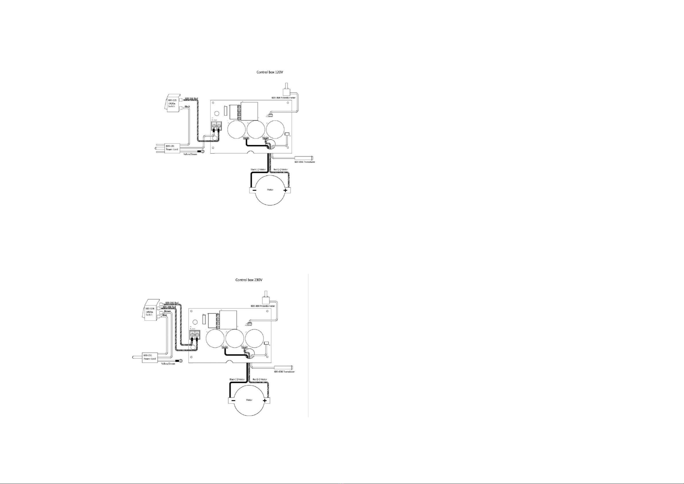
Diagram D
Diagram E
REPLACE CONTROL BOX
Follow pressure relief procedure before attempting to service or repair unit.
1. If trouble shooting guide suggests replacing the control box follow the directions
below.
2. Remove 6 screws #40 and remove cover plate #70.
3. Unthread transducer from fluid manifold #9.
4. Disconnect motor leads from circuit board. See Diagram “D/E”
5. Remove 3 mounting screws #57 from bracket #87. Unthread filter housing for easier
access.
6. Remove control box containing circuit board, On/Off switch and potentiometer
7. Replace in reverse order. Note: By removing motor housing will make it easier to
install control box.
Note: Although the Circuit board, tranducer, On/Off switch and potentiometer are sold
individually they are supplied together with replacement Control Box assembly.
REPLACE CIRCUIT BOARD
Follow pressure relief procedure before attempting to service or repair unit.
If trouble shooting guide suggests replacing the Circuit Board follow the directions below.
1. Remove 6 screws #40 and remover cover plate #70.
2. Disconnect Transducer #89 from circuit board. See diagram “D/E” and for below.
3. Disconnect the leads from potentiometer #82 to circuit board
4. Disconnect the leads from motor # 44 to the circuit board
5. Disconnect lead from On/Off switch #80 to circuit board.
6. Remove 4 screws #74 mounting Circuit Board.
7. Replace in reverse order.
Note: Make sure to wear surgical gloves when handling circuit board. They will reduce
contaminates that may come in contact with the circuit board.
REPLACE POTENTIOMETER
Follow pressure relief procedure before attempting to service or repair unit.
If trouble shooting guide suggests replacing the potentiometer follow the directions
below.
1. Remove 6 screws #40 and remove cover plate #70.
2. Disconnect the leads from potentiometer # 82 to circuit board and remove knob
#85. Remove potentiometer # 82.
3. Replace in reverse order.

REPLACE TRANSDUCER
Follow pressure relief procedure before attempting to service or repair unit.
If trouble shooting guide suggests replacing the transducer follow the directions
below.
4. Remove 6 screws #40 and remove cover plate #70.
5. Unplug the wire from #89 to circuit board.
6. Loosen housing #90 and with needle nose pyers slide traducer from filter manifold.
7. Remove 3 screws #57. Make sure to firmly hold control box in place.
8. Remove tranducer by guiding the wire through the circuit board and out the back of
the control box.
9. Install new transducer by sliding the wire through grommet #91 and guiding the wire
through grommet #86 and continuing through the circuit board.
10. Connect tranducer to the circuit board and reinstall screws #57.
11. With needle nose pylers slider transducer into filter manifold making sure o-ring #88
stays in place.
12. Tighten housing #90 and install cover plate #70 with 4 screws #40.
REPLACE ON/OFF SWITCH
Follow pressure relief procedure before attempting to service or repair unit.
If trouble shooting guide suggests replacing the on/off switch follow the directions below.
1. Remove 6 screws #40 and remover cover plate #70.
2. Disconnect the two leads from the on/off switch.
3. Remove mounting screws #78.
4. Remove switch indicator plate #79 and remove the on/off switch #80.
5. Replace in reverse order.
REPLACE MOTOR BRUSHES:
Follow pressure relief procedure before attempting to service or repair unit.
If trouble shooting guide suggests replacing the motor brushes follow the directions below.
1. Remove 3 screws #40 and remove cover #42.
2. Use a straight blade screwdriver to remove brush retaining cap to expose motor
brushes.
3. Remove motor brushes #48 one at a time. Inspect. Replace if worn or damaged
4. Reassemble in reverse order. When reinstalling motor brushes make sure to have
red and black wire leads to the back of the motor housing.
REPLACE MOTOR
Follow pressure relief procedure before attempting to service or repair unit.
If trouble shooting guide suggests replacing the motor follow the directions below.
1. Remove 3 screws #40 and remove motor cover #42.
2. Remove 4 screws #40 and remove cover plate #70.
3. Disconnect Black and Red cap/motor leads from circuit board #73. See diagram
“D/E”
4. Remove 4 screws #40 and remove cover plate # 55.
5. Unthread Transducer housing # 90 and slide Transducer #89 back from Fluid
Manifold.
6. Remove 4 screws #54 and remove crank housing and fluid manifold together.
7. Remove crankshaft #51 and thrust washer #52.
8. Remove reducer gear #50
9. Remove 2 screws # 57 from underneath. Leave 2 screws #57 that attach bracket #87
to control box #92.
10. Remove 4 screws #96 see diagram frame and siphon tubes and separate motor
complete from frame.
11. Install reducer gear # 50 into gear box and rotate fan to insure armature shaft is
engaged.
12. Install crankshaft and thrust washer #51, 52.
13. Fill gear box with # 2 lithium base grease.
14. Reconnect black and red cap/motor and transducer leads to circuit board in control
box.
15. Complete reassemble in reverse order.
REPLACE GEARS/CONNECTING ROD
Follow pressure relief procedure before attempting to service or repair unit.
If trouble shooting guide suggests replacing the gears or connecting rod follow the
directions below.
1. Remove 4 screws #40 and remove cover plate #55.
2. Remove 4 screws #40 and remove cover plate #70.
3. Remove 2 screws #25 and unthread transducer # 30 (see diagram “A”) and remove
pump/filter manifold.
4. Remove 4 screws # 54 then remove crank housing. Connecting rod can be replaced
at this point.
5. The reducer gear #50 and crankshaft #51 can also be replaced at this point.
6. Complete reassemble in reverse order.

Warranty Cover
TriTechAirless
This warranty applies only to TriTech airless sprayers that have been purchased
through an approved dealer of Aristospray UK (the exclusive importer of all
products manufactured by TriTech Industries Incorporated into the UK and
Ireland) for use in the United Kingdom, Northern Ireland, the Isle of Man, the
Channel Islands including Alderney, Guernsey and Jersey and the Republic of
Ireland only. Such TriTech airless sprayers must be for the purchaser’s own use,
not for hire purposes. Any TriTech airless sprayers not supplied by an approved
dealer or for use in regions other than those listed are expressly excluded from
this warranty.
Motor & Drivetrain Lifetime Warranty
The motor, motor brushes and drive train are warranted to the original purchaser
only under normal use and service against defects in craftsmanship or material
for the lifetime of the product.
Wearing Parts Two Year Warranty
Should the packings, piston or prime valve need replacing within two years of
the original purchase this will be carried out by an approved service agent at
no cost to the purchaser; this is limited to a one-time change only within the
warranty period.
Craftsmanship Four Year Warranty
Outside of what is listed in the ‘Motor & Drivetrain Lifetime Warranty’ and the
‘Wearing Parts Two Year Warranty’ TriTech airless sprayers are warranted under
normal use and service against manufacturing defects for four years from
the date of original purchase. This includes the frame, the controller box and
associated componentry and all other parts not specically listed. Tyre failure
due to puncture (where applicable) is excluded.
Other manuals for T4 Airless Sprayer
1
This manual suits for next models
12
Table of contents
Other Tritech Paint Sprayer manuals


