Triumph A9808092 User manual

EN
Fitting Instructions:
Daytona 675
Alarm/Immobiliser - A9808092
Thank you for choosing this Triumph genuine accessory kit. This accessory kit is the product of
Triumph's use of proven engineering, exhaustive testing, and continuous striving for superior
reliability, safety and performance.
Completely read all of these instructions before commencing the installation of the accessory kit in
order to become thoroughly familiar with the kit’s features and the installation process.
These instructions should be considered a permanent part of your accessory kit, and should remain
with it even if your accessory equipped motorcycle is subsequently sold.
Parts Supplied:
1. Alarm/Immobiliser kit 1 off 4. Bungee strap 1 off
2. Fitting kit 1 off 5. Battery drainage label 1 off
3. Fitting instructions 1 off
Publication part number A9900449, Issue 2, ADC 9148
© Triumph Designs Ltd 2009.

EN
Note:
• Power supply voltage range -
12 volt DC negative earth.
• System current consumption
<2.5 mA in armed condition.
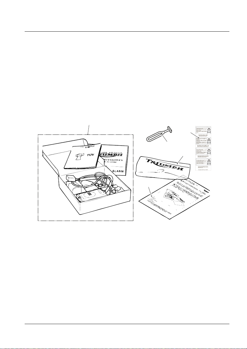
• Record the serial number and tag
number from the underside of the
alarm unit on to the alarm
installation certificate.
• Once the Alarm/Immobiliser has
been fitted, it will become an
integral part of the motorcycle and
cannot be removed.
• A suitable heat gun and hand-held
power drill fitted with a 2 mm
diameter drill bit are required to fit
this kit.
Reed-switch Fitment
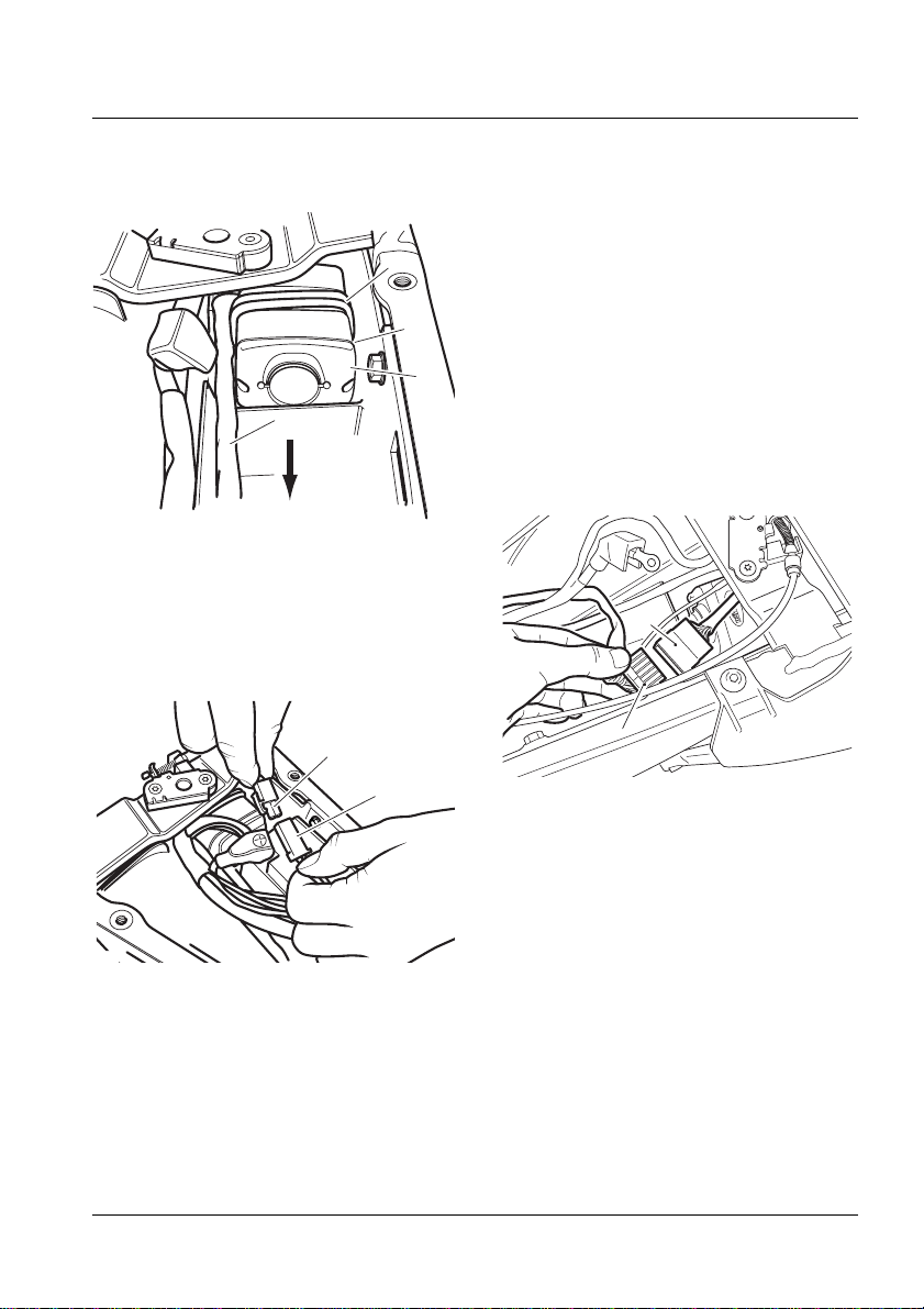
1. Remove the seat and disconnect the
battery, negative (black) lead first.
2. Undo the battery strap and remove the
battery.
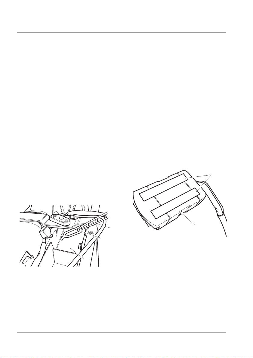
3. Place the seat on a clean non-abrasive
surface and note the position of the two
fixing holes shown.
Warning
This accessory kit is designed for use on
Triumph Daytona 675 motorcycles only and
should not be fitted to any other Triumph
model or to any other manufacturer’s
motorcycle. Fitting this accessory kit to any
other Triumph model, or to any other
manufacturer’s motorcycle will affect the
performance, stability and handling of the
motorcycle. This may affect the rider’s ability
to control the motorcycle and could cause an
accident.
Warning
Always have Triumph approved parts,
accessories and conversions fitted by a
trained technician of an authorised Triumph
dealer. The fitment of parts, accessories and
conversions by a technician who is not of an
authorised Triumph dealer may affect the
handling, stability or other aspects of the
motorcycle’s operation which may result in
loss of motorcycle control and an accident.
Warning
Throughout this operation, ensure that the
motorcycle is stabilised and adequately
supported on a paddock stand to prevent
risk of injury from the motorcycle falling.
Warning
Always ensure that newly installed wiring
does not chafe against other parts of the
motorcycle such that they may be rubbed
through and cause an electrical problem. In
addition, always ensure that newly installed
wiring will not restrict steering movement.
Both conditions are hazardous and could
give rise to a dangerous riding condition
resulting in a fire, loss of motorcycle control
and/or an accident.
Publication part number A9900449, Issue 2, ADC 9148
© Triumph Designs Ltd 2009.

EN
Note:
• The fixing holes are pre-formed and
do not require drilling.
1. S e a t
2. Fixing holes
4. Secure the reed-switch magnet from the
fitting kit to the fixing holes with the two
screws supplied.
Note:
• Ensure the magnet is fitted in the
orientation shown below.
1. S e a t
2. Reed-switch magnet
5. Position the reed-switch between the two
moulded lines on the right-hand side of
the battery box area. The top of the
reed-switch should be level with the top of
the frame.
1. Frame
2. Moulded lines
3. Reed-switch
Note:
• Only drill through the plastic
moulding. Do not drill into any part
of the motorcycle frame.
6. Mark the position of the reed-switch fixing
holes, remove the reed-switch and drill a
hole in each marked position using a
2 mm diameter drill.
Note:
• Read the warning notices printed on
the cleaning wipe packet in the
fitting kit.
• The surface to which the
reed-switch is affixed must be clean
and dry to ensure that the adhesive
has a sound base to adhere to. Use
the cleaning wipe supplied for this
purpose.
2
1
cdsb
2
1
cdsc
1
3
2
cdsd
Publication part number A9900449, Issue 2, ADC 9148
© Triumph Designs Ltd 2009.

EN
7. Peel off the backing strip from the
adhesive pad on the reed-switch. Place the
reed-switch in position and secure using
the screws supplied.
Alarm Unit Fitment
1. Recover the rubber bungee strap from the
fitting kit and insert into the hole in the
accessory alarm compartment.
Suggested method
• Insert a length of spare electrical cable
through the loop in the bungee.
• Feed both ends of the cable through the
hole in the accessory alarm
compartment from underneath.
• Pull the bungee through the hole with
the cable until the shoulder of the
bungee abuts the underside of the
accessory alarm compartment.
• Remove the electrical cable.
1. Accessory alarm compartment
2. Bungee strap
3. Electrical cable (for fitment of bungee
only)
Note:
• Read the warning notices printed on
the cleaning wipe packet in the
fitting kit.
• The surface to which the foam pads
are affixed must be clean and dry to
ensure that the adhesive has a
sound base to adhere to. Use the
cleaning wipe supplied for this
purpose.
2. Unclip the alarm connector from the
battery tray and, leaving the accessory
alarm compartment clear, move the
connector to one side.
3. Recover the two self adhesive foam pads
from the fitting kit, peel off the backing
strip from the pads and affix to the bottom
of the alarm/immobiliser unit as shown.
1. Alarm/immobiliser unit
2. Foam pads
4. Insert the alarm/immobiliser unit into the
accessory alarm compartment, positioned
with the alarm/immobiliser wiring facing
the REAR of the motorcycle and foam
pads at the bottom. Stretch the rubber
CDRY
1
2
cdrz
Publication part number A9900449, Issue 2, ADC 9148
© Triumph Designs Ltd 2009.

EN
bungee over the unit and loop the end
over the hook moulded into the side of the
compartment.
1. Alarm/immobiliser unit
2. Alarm/immobiliser wiring
3. Rubber bungee
4. Hook location
5. Connect the reed-switch wiring to the
alarm/immobiliser wiring.
1. Reed-switch wiring connector
2. Alarm/immobiliser wiring connector
6. Locate the black, twelve pin connector on
the main wiring harness and remove the
connector shorting plug.
Note:
• The alarm connector is an unused
black coloured terminal block. The
shorting plug is the cover for this
terminal block which is fitted with a
double hoop of black cable.
• The shorting plug must be returned
to DATATOOL along with the
registration documentation.
7. Slide the supplied heat shrink tubing over
the alarm/immobiliser connector. Do not
shrink the tubing at this time.
8. Connect the alarm/immobiliser wiring to
the main wiring harness connector.
1. Main wiring harness connector
2. Alarm/immobiliser connector
9. Refit the battery and secure with the
battery strap.
10. Reconnect the battery, positive (red) lead
first.
11. Replace the motorcycle seat and check all
the functions of the alarm as detailed in
the user guide.
&RONTOF
-OTORCYCLE
CDSA
cdga
2
1
Publication part number A9900449, Issue 2, ADC 9148
© Triumph Designs Ltd 2009.

EN
Note:
• When satisfied that the
alarm/immobiliser is functioning
correctly, the connection between
the alarm/immobiliser unit and the
main wiring harness must be made
secure and tamper proof with the
heat shrink tubing.
12. Remove the seat, disconnect the battery,
negative (black) lead first and remove the
battery from the motorcycle.
13. Using a heat gun, shrink the heat shrink
tubing to secure the connection.
Note:
• If required use cable ties to secure
both ends of the heat shrink tubing.
14. Route the alarm/immobiliser wiring tidily
and secure with the supplied cable ties.
15. Refit and reconnect the battery, positive
(red) lead first.
16. Refit the seat.
Warning
To prevent the risk of the battery exploding
and to prevent damage to electrical
components ensure that the battery is
removed from the motorcycle prior to the
use of the heat gun.
Failure to observe the above warnings may
lead to electrical damage and a fire hazard
which could cause personal injury.
Warning
The air from a heat gun, and the heat gun
itself, are very hot. Wear suitable protective
gloves and do not point the heat gun at any
part of your body as serious burns to the skin
may result.
Caution
When fitting the heat shrink tubing, take
care not to burn any part of the wiring
harness or serious damage will result to the
cable. Excessive heat will also cause the
tubing to become brittle rendering it useless.
Publication part number A9900449, Issue 2, ADC 9148
© Triumph Designs Ltd 2009.

EN
Alarm kit contents
Fitting kit contents
Note:
• It is a Thatcham requirement that
the MIRRC evaluation number is
also shown on the certificate of
installation supplied to the
customer. This evaluation number
varies from Triumph model to
model, dependent upon the fitting
kit used.
• Write the relevant MIRRC
evaluation number as indicated
below onto the certificate of
installation, next to the alarm serial
number.
1. A l a r m u n i t 1 o f f
2. Transmitter 2 off
3. S4 user guide 1 off
4. Quick reference guide 1 off
5. Certificate of installation 1 off
1. Adhesive backed reed switch 1 off
2. Adhesive backed magnet 1 off
3. 3 mm self tapping screws 4 off
4. Adhesive backed foam pads 2 off
5. Cable ties 5 off
6. Isopropanol wipe 1 off
7. Application chart 1 off
8. Heat shrink tubing 1 off
9. Lanyard 1 off
10. Set of key blade conversion
fillets
2 off
Triumph
kit part
number
Type Model MIRRC
evaluation
number
A9808092 R Daytona
675
TMC1 - 232 /
1105
Warning
If, after fitment of this accessory kit, you have
any doubt about the performance of any
aspect of the motorcycle, contact an
authorised Triumph dealer and do not ride
the motorcycle until the authorised dealer
has declared it fit for use. Riding a
motorcycle when there is any doubt as to
any aspect of the performance of the
motorcycle may result in loss of control of
the motorcycle leading to an accident.
Warning
The motorcycle must not be operated above
the legal road speed limit except in
closed-course conditions.
Warning
Only operate this Triumph motorcycle at
high speed in closed-course on road
competition or on closed-course racetracks.
High speed operation should only be
attempted by riders who have been
instructed in the techniques necessary for
high speed riding and are familiar with the
motorcycle’s characteristics in all conditions.
High speed operation in any other
circumstances is dangerous and will lead to
loss of motorcycle control and an accident.
Publication part number A9900449, Issue 2, ADC 9148
© Triumph Designs Ltd 2009.
Other Triumph Security System manuals
Popular Security System manuals by other brands

SICK
SICK RAM620-10x01 operating instructions

Risco
Risco Agility user manual

Corrsys Datron
Corrsys Datron Correvit SFII P user manual

Toa
Toa Netcansee N-CC2360 installation guide

TransTel Communications
TransTel Communications G1E Plus Programming & user instructions

SOMFY
SOMFY Home KEEPER Series Simplified instructions