GENERAL DESCRIPTION
Button is compatible with Extinguishing Fire Control Panel FS 5200E. It is designated for forced
activation of the extinguishing process. The button is to be mounted close to the protected premise.
Connect the button to the input “Manual Release”of Control Panel FS5200E. The connection
line is monitored for short-circuit or interruption using end of line resistance.
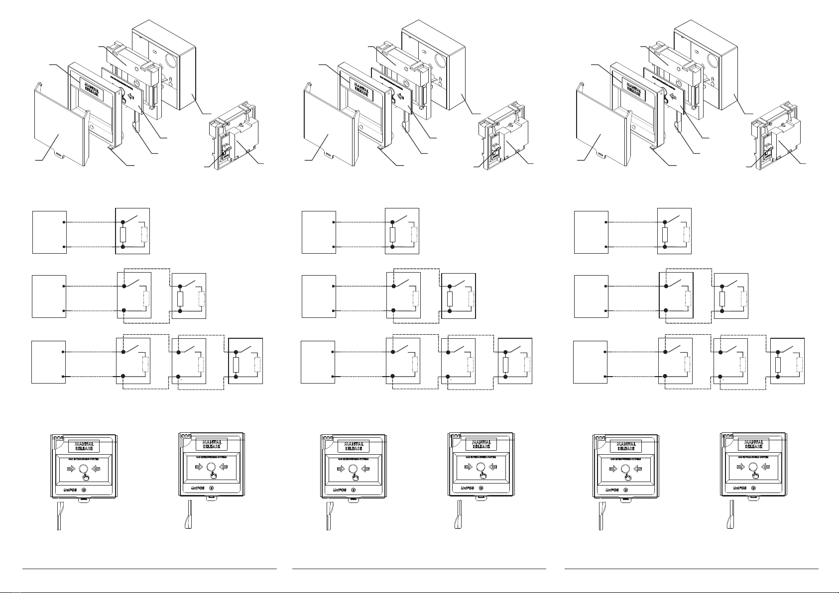
The button has a built-in switcher with one normally open contact and resistor of 1,5 k? . When
pressing the button, the contact is closed and commutates circuit through resistor of 1,5 k? . When
the button is situated at the end of the line,it is necessary to connect end of line resistance 3k? to
terminals ”+” and “-''(fig. 2a, 2b, 2c).
FD3050Y consists of : surface mounting box (pos.4,fig.1), a carrier unit (pos.3,fig.1), elastic
element (pos.5,fig.1), a test key(pos.6, fig.1), breakable seal(pos.7,fig.1), cover(pos.2,fig.1) and
protective cover (pos.1, fig 1) :
To activate the Manual Release Button:
1. Open the protective cover, fixed by means of the breakable seal.
2. Press the elastic element by mechanic impact on the marked place by the arrows.Forced
extinguishing is activated.
To enable the button Manual Release
1. Insert the spiral end of the key into the hole (fig.3) and press-to-end. The elastic element should
fall.
2. Place the flat end of the key into the hole (fig.3) and press-to-end. The elastic element must
return to its original position.
3. Dismantle the cover (pos.2, fig.1) and replace the torn breakable seal (pos.7, fig.1).
4. Mount the cover by the reverse order and fix the protective cover by the breakable seal.
5. The button is ready for new activation.
TECHNICAL DATA
Switcher one normally open contact (NO)
Electrical installation by means of terminal for installation
2
wires with cross section (0,8-1,5) mm
Degree of protection IP 40
Operating temperature range from minus 10°C to plus 60°C
Relative humidity resistance (93±3)% at 40°C
Dimensions 90 õ 90 õ 44 mm
Material ABS, yellow
INSTALLATION
To install the button, please observe the following sequence:
1. Dismantle the basic components of the unit : the cover,the carrier unit, and the back box shown
on fig.1 by unscrewing the fixings.
2. Fix the back box on the wall by and dowels and self-tapping screws.
3. Join the wires of the input line to terminals (pos.8, fig 1a), located on the rare side of the carrier
unit (pos.3, fig. 1).
4. If the button is the last one of several buttons FD3050Y (Fig 2b, 2c), additionally add end of line
resistance of 3k? to terminals ''+'' and ''-'' for equalizing the line.
5. Consecutively mount to the back box of the button the following elements the carrier unit, the
breakable seal, the elastic element with the sticker to the cover and the cover.
6. Fix the protective cover to the back box by means of the breakable seal.
7. Cut off the spare end of the breakable seal. Thus the breakable seal can be used twice for fixing
the protective cover and indicates that the button has been used once
TESTING
The manual call point is tested after installation, as a part of the Extinguishing Fire Alarm System or
after performing service schedule:
1. Testing
1.1. Turn on switcher Disable Extinguishing of the Control Panel.
1.2. An indicator ''Disable Extinguishing'' lights on in the Control Panel.
1.3. Insert the spiral end of the test key in the opening (fig.3) and press to end. The elastic element
should fall. The button is activated.
1.4. The Control Panel enters Fire Condition 2nd Stage. The relevant indicator lights on.
2. Enabling
2.1. Place the flat end of the key into the opening (fig.3) and press to end. The elastic element
should move into its initial position.
2.2. The button is ready for use.
2.3. Restart the Control Panel.
2.4. Turn the mode selector key into its initial position. The indicator “Disable Extinguishing'' lights
off.
2.5. The Control Panel is in Duty Mode.
SERVICE SCHEDULE
1. Inspection for visible physical damage - weekly
2. Satisfactory operation test in real conditions - monthly
WARANTY
The warrant period is 36 months from the date of the purchase.
The manufacturer guarantees the normal operation of the fire detector providing that the service
requirements of the instruction manual herein have been observed.
The manufacturer does not bear warranty liabilities for damages, caused through accidental
mechanical damages, misuse, adaptation or modification after the production of the product.
The manufacturer bears warranty liabilities for damages in the manual call point caused through
manufacturer's fault only.
BUTTON MANUAL RELEASE
TYPE FD3050Y
INSTRUCTION MANUAL 02-3050Y-04-11
Manufacturer: UniPOS Ltd., 47San Stefano Street, Pleven 5800, Bulgaria, http://www.unipos-bg.com
GENERAL DESCRIPTION
Button is compatible with Extinguishing Fire Control Panel FS 5200E. It is designated for forced
activation of the extinguishing process. The button is to be mounted close to the protected premise.
Connect the button to the input “Manual Release”of Control Panel FS5200E. The connection
line is monitored for short-circuit or interruption using end of line resistance.
The button has a built-in switcher with one normally open contact and resistor of 1,5 k? . When
pressing the button, the contact is closed and commutates circuit through resistor of 1,5 k? . When
the button is situated at the end of the line,it is necessary to connect end of line resistance 3k? to
terminals ”+” and “-''(fig. 2a, 2b, 2c).
FD3050Y consists of : surface mounting box (pos.4,fig.1), a carrier unit (pos.3,fig.1), elastic
element (pos.5,fig.1), a test key(pos.6, fig.1), breakable seal(pos.7,fig.1), cover(pos.2,fig.1) and
protective cover (pos.1, fig 1) :
To activate the Manual Release Button:
1. Open the protective cover, fixed by means of the breakable seal.
2. Press the elastic element by mechanic impact on the marked place by the arrows.Forced
extinguishing is activated.
To enable the button Manual Release
1. Insert the spiral end of the key into the hole (fig.3) and press-to-end. The elastic element should
fall.
2. Place the flat end of the key into the hole (fig.3) and press-to-end. The elastic element must
return to its original position.
3. Dismantle the cover (pos.2, fig.1) and replace the torn breakable seal (pos.7, fig.1).
4. Mount the cover by the reverse order and fix the protective cover by the breakable seal.
5. The button is ready for new activation.
TECHNICAL DATA
Switcher one normally open contact (NO)
Electrical installation by means of terminal for installation
2
wires with cross section (0,8-1,5) mm
Degree of protection IP 40
Operating temperature range from minus 10°C to plus 60°C
Relative humidity resistance (93±3)% at 40°C
Dimensions 90 õ 90 õ 44 mm
Material ABS, yellow
INSTALLATION
To install the button, please observe the following sequence:
1. Dismantle the basic components of the unit : the cover,the carrier unit, and the back box shown
on fig.1 by unscrewing the fixings.
2. Fix the back box on the wall by and dowels and self-tapping screws.
3. Join the wires of the input line to terminals (pos.8, fig 1a), located on the rare side of the carrier
unit (pos.3, fig. 1).
4. If the button is the last one of several buttons FD3050Y (Fig 2b, 2c), additionally add end of line
resistance of 3k? to terminals ''+'' and ''-'' for equalizing the line.
5. Consecutively mount to the back box of the button the following elements the carrier unit, the
breakable seal, the elastic element with the sticker to the cover and the cover.
6. Fix the protective cover to the back box by means of the breakable seal.
7. Cut off the spare end of the breakable seal. Thus the breakable seal can be used twice for fixing
the protective cover and indicates that the button has been used once
TESTING
The manual call point is tested after installation, as a part of the Extinguishing Fire Alarm System or
after performing service schedule:
1. Testing
1.1. Turn on switcher Disable Extinguishing of the Control Panel.
1.2. An indicator ''Disable Extinguishing'' lights on in the Control Panel.
1.3. Insert the spiral end of the test key in the opening (fig.3) and press to end. The elastic element
should fall. The button is activated.
1.4. The Control Panel enters Fire Condition 2nd Stage. The relevant indicator lights on.
2. Enabling
2.1. Place the flat end of the key into the opening (fig.3) and press to end. The elastic element
should move into its initial position.
2.2. The button is ready for use.
2.3. Restart the Control Panel.
2.4. Turn the mode selector key into its initial position. The indicator “Disable Extinguishing'' lights
off.
2.5. The Control Panel is in Duty Mode.
SERVICE SCHEDULE
1. Inspection for visible physical damage - weekly
2. Satisfactory operation test in real conditions - monthly
WARANTY
The warrant period is 36 months from the date of the purchase.
The manufacturer guarantees the normal operation of the fire detector providing that the service
requirements of the instruction manual herein have been observed.
The manufacturer does not bear warranty liabilities for damages, caused through accidental
mechanical damages, misuse, adaptation or modification after the production of the product.
The manufacturer bears warranty liabilities for damages in the manual call point caused through
manufacturer's fault only.
BUTTON MANUAL RELEASE
TYPE FD3050Y
INSTRUCTION MANUAL 02-3050Y-04-11
Manufacturer: UniPOS Ltd., 47San Stefano Street, Pleven 5800, Bulgaria, http://www.unipos-bg.com