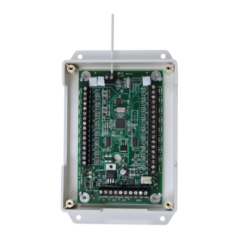
AV-CAD EasyLoader AV-2016D User manual

1
E a s y L o a d e r
AV-2016D, AV-2016DP
AV-2055D, AV-2088D
(for LED keypad)
Integrated Alarm Control/Communicator
Installation and Operation Manual
Version 3.05D
Edition II
This product is subject to continuous enhancements and therefore
specifications may be changed or altered without prior notice
Item: 4712_BIG (A4BKE)
All manuals and user guides at all-guides.com
all-guides.com

2
Table of Contents
Contents Page
SECTION I: SYSTEM FEATURES .................................................................................. 4
1. INTRODUCTION...................................................................................................... 4
1.1 General Description...................................................................................... 4
1.3 Programmable Features ................................................................................ 5
1.4 Alarm and Power Outputs ............................................................................ 5
1.5 Ordering Information.................................................................................... 7
1.6 AV-2016D, AV-2055D, AV-2088D Technical Specifications.................... 8
SECTION II: INSTALLATION...................................................................................... 10
2. MOUNTING .............................................................................................................. 10
2.1 Control Panel Mounting ............................................................................... 10
2.2 Connection of AV-816 Expander................................................................. 12
2.3 AV-2055, 2088D Wiring.............................................................................. 13
2.4 Keypad Wiring ............................................................................................. 14
3. ALARM OUTPUTS .................................................................................................. 16
3.1 Sirens ............................................................................................................ 16
3.2 Remote Indication Terminals ....................................................................... 16
3.3 Wiring and Connection of Relay Module..................................................... 17
4. WIRING AND POWERING UP ............................................................................... 18
4.1 Grounding – Lightning Protection................................................................ 18
4.2 Back-up Battery............................................................................................ 18
4.3 Before Powering Up ..................................................................................... 18
4.4 Connecting Smoke Detectors ....................................................................... 19
4.5 Telephone System Dialing............................................................................ 20
4.6 SVM – Voice module................................................................................... 20
4.7 Remote Key and Wireless Arming & Disarming......................................... 21
4.8 Remote Access via DTMF ........................................................................... 21
SECTION III: AV-701 & AV-702 DIGITAL KEYPAD............................................... 23
1.1 Standard Keypad Functions.......................................................................... 23
1.2 Hold-Down Functions .................................................................................. 25
1.3 Keypad Sounder ........................................................................................... 29
1.4 LED Indicators ............................................................................................. 30
1.5 Keypad Digital Display (7-segment type) .................................................... 31
1.6 Arm and Disarm System via AV-701/702 Series Keypad ........................... 32
All manuals and user guides at all-guides.com

3
SECTION IV: PROGRAMMING ...................................................................................... 34
1. SYSTEM CODES...................................................................................................... 34
1.1 User Code Programming via AV-701 Keypad (Not with AV-2016DP) .......... 35
2. FEATURE PROGRAMMING AT INSTALLER LEVEL ........................................ 36
2.1 Programming Table AV-20055D, 2088D, 2016D, 2016DP (V3.05)........... 36
2.2 Introduction .................................................................................................. 44
2.3 Programming Sheet Explanation.................................................................. 44
2.4 Glossary of Programmable Features............................................................. 46
2.7 Step - By - Step Programming...................................................................... 51
2.8 Reset System to Default Programming ........................................................ 55
2.9 Dialer- Communicator; explanation and Programming ............................... 55
2.9.1 Deleting Telephone Numbers ........................................................................ 56
2.9.2 User Programming of ‘Follow-Me’ Telephone Number ............................... 57
2.10 Quitting Programming Mode .......................................................................... 57
2.11 Verification of Current Programming............................................................. 57
2.12 Downloading from a computer ....................................................................... 57
3. PARTITIONED SYSTEM – TYPE AV-2016DP...................................................... 63
3.1 Partition Definition ........................................................................................... 63
3.2 AV-2016DP - Users Options ............................................................................ 64
3.3 AV-2016DP - Keypad Operation...................................................................... 64
3.4 AV-2016DP - ‘Hold Down’ Keypad Functions ............................................... 66
3.5 AV-2016DP LED Indicators............................................................................. 68
3.6 System Codes.................................................................................................... 68
4. TROUBLESHOOTING ............................................................................................. 69
SECTION V: WIRING DIAGRAM ........................................................................................ 73
SECTION VI: INDEX........................................................................................................... 74
Av-Gad Limited Warranty........................................................................................... 76
@ All Rights Reserved to Av-Gad Systems Ltd, Tel Aviv, Israel. POB 49 080 Tel-Aviv, Israel. February 2013/ VER. 3.05D Rev 1, /2016_2088_2055 3.05. Item 4712_BIG
All manuals and user guides at all-guides.com

4
SECTION I: SYSTEM FEATURES
1. INTRODUCTION
1.1 General Description
Av-Gad's EasyLoaderTM AV-2055D,AV-20088D,AV-2016D, AV-2016DP are
microprocessor based intruder alarm panels with integrated communicator. They feature 5, 8,
16 or 32 double-zone all of them are expandable and compatible to Av-Gad LED keypads.
Series 2000 represents the state-of-the-art in user-friendly, reliable alarm control panels for
security requirements of small and medium-size commercial, residential, and industrial
installations.
Av-Gad's EasyLoaderTM AV-2016 and AV-2008 versatile control panels meets, surpasses all
requirements for reliability and maintainability, and provides the added benefits of easy
installation and simple operation.
The Dublo Version is an upgraded model of the AV-2016, designed to be compatible with
AV-705, 706, 707 and AV-707B LCD (English Text) keypads. Refer the AV-2016 Dublo
manual.
The AV-2016 comprises an enhanced power supply, improved electronics, and additional
signaling indicators.
The 2000 Series innovative keypads (AV-701 & AV-702) are unquestionably the most user-
friendly remote station, designed to enable control of the system by the end-user, as well as by
the installer.
Version 3.00 news
Version 3.00: The Spare output (2016) terminal removed, DTMF control (arm, disarm, etc)
is standard, panel version identifies itself as AV-2016D (EasyLoad software), self test at
initialization (STI) - Dial LED blinks for the first 50 seconds after power on, new factory
defaults, address 052: Set the signal test per days, improved lighting protection with option for
heavy duty lighting protection, CS testing day programming. Home Automation: Activation of
A1 and SLO outputs via DTMF, First alarm indication reported via DTMF.
Version 3.04: New at 072-4, activate ON output to drive ADSL filter line disconnect, added
999 to exit programming mode, during Answer Now mode keypad display CA, improved
Contact ID format. New AV-2016 box is ready for extra AV-21 power supply and 5003TER
transformer. Version 3.05: Enable Last Zone as Aux. Key, including AV-2055D, AV-2088D.
Version 3.05A: Code 8 problem fixed. Version 3.05C: Siren wiring in case of troubles, see
section 3.1.
All manuals and user guides at all-guides.com

5
1.2 Built-in Features
Accepts Normally Closed or Normally Open alarm devices
All features are programmable via system keypad
Automatic battery test upon arming and during Disarmed or Armed mode
True low battery indication
Central station communicator and dialer. Communicator is compatible with most major
formats: Ademco Slow and Express, Radionics, Scantronic, Sescoa, Contact ID, etc
Chime programmable for each zone
Digital zone status display
Double-Pole zones. Tampering indication for each zone
Eight partitions with the AV-2016DP, compatible with LED keypads only
Keypad sounder during local alarm
Local clock and date
Modulated tone siren from 24H and panic zone(s), 3-tone alarm from burglary zones
Programmable four or five output drivers for remote signaling and reset of smoke detectors
Programmable 16 or 32 EOL resistor zones, or non-EOL zones
Pulse-operated battery charging circuit
Two dialing modes: Pulse or DTMF. Dialing to pagers in Hong-Kong and Singapore
Signals to central station monitoring (via wire or wireless)
Up and Download from a computer, or via telephone line
Up to 250 alarm logs, with event time
Up to 8 or 16 user codes, each code one to six digits. One installer code, access control code
Up to 32 (2016) EOL supervised double-zone. One Panic zone at keypad
1.3 Programmable Features
Thirty-two End-Of-Line zones (with AV-816), EOL zone enable or disable
Individual entry delays for two zone groups.
Automatic bypass of open (troubled) ‘instant’ zones upon arming
Selective and Zone Group Bypass (Group Shunt for Home Mode)
24-hour zones, fire zone
Zone types: Delayed, Follower, Fire, Not in use, Day, Tamper, Panic zone and more
Selectable response time for individual zones
1.4 Alarm and Power Outputs
Five programmable open collector output drivers for remote alarm signaling
Contains auxiliary output for electric strike operation
Communicator to central station and alarm sound dialer
Keypad sounder alarm programmable by zone
Two timed siren outputs, protected by separate fuses
Variable sirens alarm sound for different types of zones
Two separate fused protected auxiliary power (12V) outputs
All manuals and user guides at all-guides.com

6
Signal test to central station, signaling time and day are programmable
Programmable ‘Bell Mode’
SPR output toggle mode via hold down key
Remote Signals:
24H-zone Alarm
On/Off (Arming/Disarming) indication
Central station Signal Test. Transmitting time is programmable
Panic, Tamper alarm
Programmable output for each zone or event (SLO output)
All manuals and user guides at all-guides.com
all-guides.com

7
1.5 Ordering Information
Item Code
Description
AV-2016D
AV-2016D4F
16 + 1 double-zone Alarm Control Panel and Communicator/
Dialer. Supports AV-701, AV-702 keypad. Approved for EEC
telephone (“E” mean CTR-21 compatible). AV-2016D4F with four
outputs controlled by DTMF for remote appliances activation
AV-816
16 zone expanding module compatible with AV-2016
AV-208
8 zone expanding module compatible with AV-2055, 2088D
AV-2016DP
16 + 1 zone Alarm Control Panel and Communicator / Dialer, with
eight partitioned. Supports AV-701, AV-702
2055_4PCB
Board only for AV-2055D (5 or 10 zone expandable to 26)
2088_4PCB
Board only for AV-2088D (8 or 16 zone expandable to 32)
2016P_4PCB
Board only for AV-2016DP
2016_4PCB
Board only for AV-2016D
TMP
Tamper switch with wires for main alarm metal box. Not supplied,
requires special order
AV-701TS
4-wire Keypad. 7-segment Digital Display, 4 LEDs, 12 silicon
rubber keys, semi-back light, local sounder. Connected to panel via
4 terminal wires. Compatible with AV-2016D, AV-2016DP
AV-701TI
AV-701TP
Identical to AV-701TS, with additional timed backlight
illumination. AV-701TP includes Tamper protection
5003TER
Fuse-protected 220V step-down to 16V-1.2A AC transformer for
AV-2055, 2088D Series
5005TER
Fuse-protected 220V step-down to 16V-1.7A AC transformer for
AV-2016 Series
AV-702 and
AV-702TP
(Tamper
added)
New shape housing. Improved circuitry provides longer wiring and
better communication. 4-wire Keypad. 7-segment Digital Display, 4
LEDs, 12 silicon rubber keys with protection door, local sounder
RELAYMO
Relay module for driving self-powered siren in Series 2000. (Used
in France, Italy, UK and other countries.)
SVM-40/60
Speech module, record & play, message stored without power, 40 or
60 seconds message. Two channels. For message recording an on-
board microphone is included
AV-21, AV-21B
and AV-40
Extra 12V-1A or 4A, power supply and charger, supplying the
power for large installations. AV-21 supplied as PCB.
With AV-21B the PCB housed in box. AV-40 is 4A type
All manuals and user guides at all-guides.com

8
1.6 AV-2016D, AV-2055D, AV-2088D Technical Specifications
Operating Temperature
-10C to 60C
Relative Humidity
80% maximum
Input AC Power
16V AC step-down Transformer 1.7 Amp
Dynamic Inner Memory
EPROM and SRAM
Auxiliary Power Output
13.8 Volts +/- 5%, Regulated
Short & Overload circuit protection
Siren Outputs (x2)
Siren or Bell Selectable
Bell Mode: 14V DC-2 x 0.7A (1.4A)
Siren: 8 Ohms, 20W Max.
Programmable Dialer: 3 telephone numbers &
1 Follow Me telephone number (4 phone
numbers)
Multi-format central-station communicator
Pulse Dialing parameters programmable
DTMF: Touch Tone dialing
Max. Telephone number length: 16 digits
and 4 pauses
Remote Indications on Wire Terminal
Open Collector type output
300 mA Max. @ 12V DC
EOL Zone Loop Resistor (Burglary)
EOL Zone Loop Resistor (Tamper)
2,200 Ohms, 0.25W, +/- 5%
4,700 Ohms, 0.25W, +/- 5%
Zone Loop Voltage
5 to 6.5V DC
Zone Loop Current
3 mA with End-Of-Line Resistor
Line Protection
Zone line shorting, cutting, high voltage
lightning protection, RF Metal Screen,
Electro Static Discharge Traps, RF Filters.
Telephone line Lighting protection circuit
Auxiliary Power (Max.)
13.8V DC 1.4A Combined AUX. Power
and Keypad outputs 13.8V DC-0.6A
Battery Charging Current (Max.)
550 mA, current limitation
Battery Test: Indication at keypad or remote
indication via communicator
Performed at 0.5A load for 1 second.
Low Battery indication below 10.5V
Tested upon Arming, and every 4 minutes
during Armed, every 1 hour during
Disarmed
Standby Power Consumption at disarmed
mode, and Keypad display is Off
110 mA, +/- 10 %
Max. Remote Station (Keypads)
Five keypads AV-701TS, AV-701TI, AV-
702. Eight AV-707 keypads
Remote Station Current Consumption
AV-701TS: 27mA. AV-701TI: 36mA
AV-702: 40mA.
Housing (AV-2055D, AV-2088D in ABS
plastic box)
ABS plastic
Housing Dimensions (AV-2016D)
(H) 32, (D)9, (W)36 cm
Housing Dimensions (AV-2055D, 2088D)
(H) 30, (D) 9, (W) 23 cm
All manuals and user guides at all-guides.com

9
Gross Shipping Weight (2055D, 2088D)
AV-2000: 1 kg. Six units per master box
Gross Shipping Weight
AV-2016: 3.6 kg. Three units per box
Fuses: Electronic Fuse
Auxiliary Power: 1.5A Electronic
Keypad Power (2016): 1.5A Electronic
Sirens: 1.5A Electronic
Backup Battery Fuse: 3A Electronic
Av-Gad Systems Ltd. reserves the right to modify and upgrade products without prior notice.
Electronic Fuse Overview
The Electronic Fuse device included as a series element in electric circuit. In response to an over current it
protects the circuit by going from a low-resistance to a high-resistance state that reduces the current to a level
that’s safe for the circuit elements. The change in resistance is the result of a rapid increase in the
temperature of the device. Like traditional fuses, Electronic Fuse devices interrupt the flow of dangerously
high current. However, unlike traditional fuses, they automatically reset after the fault cleared and power to the
circuit removed. Because they are solid-state, Electronic Fuses are also better able to withstand mechanical
shock and vibration, and provide reliable protection in a wide variety of applications. In case of over current,
carefully touch the fuse body (yellow round disc), hot body means the Electronic Fuse in protection mode,
disconnect the load and wait 2-3 minutes until the fuse body get cooler.
Tips to first time installer
If you are a first time installer, do not hook up any remote sensors at first. The most common
confusion comes about when the alarm will refuse to arm, because a zone is “troubled”.
Complete the power supply, siren, keypad and strobe wiring, and for the moment connect ALL
the zone terminals to –V. This will simulate a system with all zones looped out through closed
switches. The alarm is supplied already programmed with an “average” list of settings (default)
and can be used straight away, a few of the program locations may have to be changed to suit the
actual sensors and output devices used.
Read this manual carefully, it looks complicated, but all the information is there
The AV-2055D, 2088D, 2016D and AV-2016DP support LED keypad only; do not connect LCD keypad
To start with: Hook up the keypad, connect all zones to –V, power-up by applying AC only
In case the keypad (LED or LCD) displays ‘garbage’ verify the minus (-V) wire connection
Arm and disarm the system, when the Status LED light (not blinking), enter your master code; 1234
Try the hold-down functions. Hold each key for approximately 2 seconds; follow the confirmation letters
in keypad’s display. In the PRO panel press the # to confirm the hold down command
Set the system time by holding-down key ‘0’ then ‘1’, set time in 24H format, blinking ‘h’ stop
The default programming is set for siren alarm device that requires 12V to alarm (Bell Mode)
Connect the Strobe Light to the SLO output (requires programming). The SLO supplies –V during alarm
Make sure you are using the Earth terminal for Grounding; it is not a minus terminal
Typing six erroneous codes will lock the keypad keys for 30 seconds
Fast test: Verify “Dial LED" self test at initialization (STI) - Blinks for the first 50 seconds after power on,
confirms panel is operative, from keypad wait to six beeps to confirm communication OK.
All manuals and user guides at all-guides.com

10
SECTION II: INSTALLATION
System planning
When the panel reaches you features set at “Factory Defaults”. This done for testing purposes
and for simple installation without first entering to programming. This present program is
referred to as ‘Factory Defaults.’ The engineer should be familiar with all the features and
options before attempting to program. System supplied with or without transformer according to
approval requirements in each country. Specify and order the keypad (several types available).
Default arming code is 1,2,3,4. Default programming code is 1,9,9,4.
2. MOUNTING
2.1 Control Panel Mounting
Refer to detailed wiring diagram on section V. Note: ‘h’ is displayed after power-up to remind
installer and user to set the system time; ‘h’ sign disappears after time setting (by hold down
keys 0 then hold down key 1, refer to page 26).
Select a mounting location accessible to the following:
1. A continuously powered (non-switched) AC power source, compatible with step-down
transformer. Make sure the mains (110 or 220V) are fused
2. A cold water pipe Ground, ideally no farther than 3 meters (10 feet) from the panel. Use
16 AWG (0.5 mm2 wire)
3. Telephone line socket
Always install the control panel box in a hard-to-access location.
Locate one of the Keypads near the Entrance/Exit door.
Install a tamper-switch to prevent opening or removal of the control panel box. Connect the
tamper-switch to a 24H zone.
Zone Wiring Mode
Via programming, select either End-Of-Line (EOL) Resistor Protection, or non-EOL mode.
If EOL mode selected (recommended), install the EOL Resistor (2.2K/0.25 or 0.5W) inside the
detection device (e.g. PIR, Magnetic Switch). To disable EOL enter ‘0’ to EOL zones address.
Note: ‘Zone’ and ‘Sector’ are interchangeable terms in this manual.
IMPORTANT! Never run wire zones alongside telephone wires, high voltage wires, or
transmitting antennae. Test your system daily.
All manuals and user guides at all-guides.com

11
Double-Pole Zone wiring
This feature saves on wiring and doubles the zone quantity by using two wires instead of four,
for both TAMPER and ALARM indications.
Use always an EOL resistor; EOL prevents EMI and RFI interference
To activate Tamper Alarm, fit the zone with two EOL resistors, program ‘Enable Zone Tamper’
feature (address number 144, 145, 146, 147) and enable ‘EOL Resistor Zone’, entering the data
at address (140, 141, 142, 143).
To enable the EOL mode program the zone selected as EOL zone. For example: To enable zones
1, 2, 3 as EOL zones; in address 144; program 1, 2, 3 removed.
Any EOL zone will report Tamper alarm in case of zone shorting (if it has been EOL
programmed). To enable Tamper zone as 24H zone refer to address 075/1.
Upon Tamper alarm, a ‘t’ displayed, followed by the zone number. To disable Tamper alarm,
hold down key ‘9’. To display Tamper zone history, hold down key ‘0’ then key ’3’.
Use PIR, other sensor or Siren box alarm device that contains two separate switches or relay
contacts: One for Alarm and one for Tamper. Connect each contact to a different EOL resistor.
Alarm contact connected in series with 2.2K and Tamper contact with 4.7K resistors. Both
resistors supplied with each system.
Figure 1: Double-Zone Wiring to EYS II PIR
All manuals and user guides at all-guides.com
all-guides.com

12
Some countries are used to different double-pole wiring as shown in figure 1A. For this wiring,
follow the drawing. European double-pole wiring requires 1.5K resistors (1.5K resistors not
supplied).
Figure 1A: European Double -Pole wiring drawing
2.2 Connection of AV-816 Expander
Figure 2: Zone Expander Wiring
Mounting
Place the AV-816 board on the left side of the AV-2016 board as the drawing shows.
Use two screws to tighten the AV-816.
Connection
Make sure power and battery are disconnected.
Plug the wires connector of AV-816 to J1 socket at the AV-2016, refer to figure 2 drawing.
All manuals and user guides at all-guides.com

13
Zone Wiring Mode
Via programming, select either End-Of-Line (EOL) Resistor Protection, or non-EOL mode.
If EOL mode selected, install EOL Resistor (2.2K/0.25 or 0.5W) inside the detection device (e.g.
PIR, Magnetic Switch).
To enable EOL mode programming and resistors required.
To enable the Tamper Alarm of each zone, refer to the programming table and set the required
zone by programming address number 144, 145, 146, 147.
Wiring details are available in the AV-2016 manual, see Double-Zone wiring chapter.
Programming
Program the ‘Zone in Use’ feature for the required zones (address 102 and 103). By default,
program zones 1-16 set as ‘Zone in Use’.
2.3 AV-2055, 2088D Wiring
The AV-2088D contains eight zone terminals. Via programming, the panel becomes 16 zones,
when zone doubling used. Adding the AV-208 the panel expand to 32 zone. Refer to figure 3.
AV-2088D is compatible with AV-701, AV-702.
Figure 3: Zone Wiring AV-2055D, AV-2088D
AV-2055D: Default is five zones. To expand to 13 zones add the AV-208 expander board (not
supplied). Zones on the expander counted zone 6 to zone 13. In ABS box insert the AV-208 in
the left side of the box (grooves to fit), in metal box use the four supplied spacers).
All manuals and user guides at all-guides.com

14
In "Double Zones" mode (074-8, must use EOL resistors) both board and expander zones are
doubled. Program the relevant zones as In Use (address 101), it provides 10 zones on the main
panel board (1 - 10).
Zone 6 connected to terminal 1, 7 to 2, 10 to 5.
Using an eight-zone expander in double zone mode: First zone on the expander count as zone
11. Zones are counted 11 to 18 - connected to terminals 9 to 16 on the expander (use 2K2
resistors). Zones are counted 19 to 26 - connected to terminals 9 to 16 on the expander (use 4K7
resistors).
Zones on panel: 1 2 3 4 5. Zones on expander: 6 7 8 9 10 11 12 13 (without resistors)
Double zone: 1 2 3 4 5. Zones on expander: 11 12 13 14 15 16 17 18 (2K2 resistor)
Double zone: 6 7 8 9 10. Zones on expander: 19 20 21 22 23 24 25 26 (4K7 resistor)
2.4 Keypad Wiring
Up to four AV-701TS/TI, or five AV-702 Keypads can be connected to AV-2016D Control
Panels, maximum three keypad with AV-2055D, 2088D. Use only AV-701 or AV-702 keypad.
For more keypads, add external power supply.
Important: Consider adding a power supply when using more than max. keypads
Connect all keypads in parallel. Do not connect keypad with power on. Each keypad contains
four wires terminal:
Red (+) Power, connect to + Aux. Power Orange System Data, connect to OR
Black (-) Power, connect to - Aux. Power Yellow System Strobe, connect to YE
For proper connection, refer to wiring diagrams on next page and at the end of the manual.
IMPORTANT! Never run Keypad wires alongside telephone wires, high voltage wires, or
transmitting antennae. Wire the keypad wires separately and not in same cable with other
devices (telephone, PIR sensor etc.). Do not use the keypad wires for supplying power to
sensors or other devices. Keypads have no polarity protection; verify 12V power carefully
during wiring.
Wire length for each AV-701 keypad better not exceed 100 meters (using 0.5 mm2 wires).
If installation requires keypad wire length of more than 100 meters, or more than five
keypads:
1. Add a 470-ohm resistor between +12V and YE terminal in the control panel
2. Use two wires for the –V that supplies the keypad power
Maximum wiring length for AV-706, AV-707 and AV-702 keypads is 200 meters (when
using 0.5 mm2 wires).
Power at Keypad should be a minimum of 11.5 Volts.
Note: If a non-blinking ‘8’ displayed and keys do not respond, it is an indication that the
keypad is not communicating with the panel. Check wiring. Polarity error may blow the
panel fuse.
All manuals and user guides at all-guides.com

15
C10
++
C12
++
C13 +
+
C14 +
+
C15C16
++
C17 +
+
C18
C19
D33
+BATTERY
-BATTERY
F10
J1
R1 R2 R3 R4
R33
R34
R35
R42
R43
R44
R46
R73
R74
R93
R94
R97
R98
R99 R100
R101R102
U3
VA1
VA2
VA3
VA5
VA6
C11
+
D2
D3
D4
D5
F7
R22
R24
VA8
U13
D14
D16 D17
R36
U7 D25
R62
R20
R26
D1
D10
D34
R39
R45
C60
Q5
D32
+12V 1 2 3 4 -V
MUST CONCT-V TO AV-816
TM1
OR
-V
+12V
KEY
SIR2
SIR-
SIR1
AC
AC
YE
AUX 12V FUSE
K.PAD 12V FUSE
1.25A 1.25A
SIR1 AND SIR2 FUSES
1.25A 1.25A
BAT. FUSE D9
D15
D21
R37
R51
R53
RF4
VA9
R59
D20
Q1
C B E
R41
D19
R40
F11
RN1
R52
R60
Q4
F3
D18
-12V
OR
YE
+12V
-12V
TMP
EOL Resistor
Tamper Sw (Optional)
Keypad's Tamper Sw' connected to zone No. 1
Keypad Power
Back side of AV-701TIP keypad
Figure 4: Wiring Keypad AV-701TS/TI, AV-701TIP
*
7
4
1
0
8
5
2
#
9
6
3
Siren
Shunt
Display Status
Delay
Delete Chime
Test Program Reset
Shunt
Telephone
ARMED STATUS SHUNT FIRE
ZONE
DISPLAY
EASYLOADER AV-701AV-GAD AV-GAD EASYLOADER AV-701
FIRESHUNTSTATUSARMED
Test
Delete
Delay
Siren 1
4
7
*
DISPLAY
ZONE
Telephone
Shunt
ResetProgram
Chime
StatusDisplay
Shunt 3
6
9
#
2
5
8
0 *
7
4
1
Siren
Delay
Delete
Test
ARMED STATUS SHUNT FIRE
EASYLOADER AV-701AV-GAD
DISPLAY
ZONE
Telephone
Shunt
ResetProgram
Chime
StatusDisplay
Shunt 3
6
9
#
2
5
8
0
AV-GAD EASYLOADER AV-701
FIRESHUNTSTATUSARMED
Test
Delete
Delay
Siren 1
4
7
* 0
8
5
2
#
9
6
3
Shunt
Display Status
Chime
Program Reset
Shunt
Telephone
ZONE
DISPLAY
Panel Panel
Wrong Wiring Correct Wiring
Figure 5: Best way wiring keypads
For trouble free operation follow the recommended wiring as shown in figure 5 drawing, wire
each keypad to the panel directly, avoid to run wires from one keypad to next (as shown the on
the ‘Wrong Wiring’).
Keypad Tamper Switch
The AV-701TIP, AV-702TP keypads (keypad with tamper switch) contain a Tamper switch that
activates upon trying to remove the keypad after installed. Connect the Tamper switch to
Tamper, Day or 24H type zone. For connection, refer to keypad’s wiring diagram.
All manuals and user guides at all-guides.com

16
3. ALARM OUTPUTS
3.1 Sirens
Control panel enables driving of two separate speaker sirens or bells.
Speaker siren issues a multiple-tone alarm. Use 14W, 8 to 16 ohm speaker siren.
Bell mode (sounder that works on 12V DC) is available via programming.
Enclose the outdoor siren in a metal box tamper-switch protection.
Protect siren or bell box with tamper-switch connected to a 24H zone.
The control unit contains two siren outputs, for internal and external siren, individually
protected by fuses.
If Siren mode selected, use speaker type siren with a minimum power of 15W, 8 Ohms
impedance. Enclose the outdoor siren in a metal housing, with anti-tamper switch
protection.
In Siren mode, install only speaker-type sirens, which DO NOT contain sound driver or
electronic modules.
The alarm issued by the Siren (not Bell mode) differs according to the type of zone.
‘Bell Mode‘ is default-set at factory. Bell converts Siren outputs into 13.6 VDC outputs (no
sound is issued). Bell mode is applicable for driving self-powered sirens or bells, or
combined sirens and strobes.
In Bell mode, connect only Bell or sirens that contain a 12V sound electronic driver
module. Bella sirens are compatible and feature high sound level at very low current use.
Self-contained Bell mode is programmable (address 071). This mode allows connection of
Bells or Sirens that require 12V at ideal and 0V during alarm. The Bell output voltage
regulated at about 13.6V. For self-contained siren, it is recommended to use Av-Gad Bella 2
or Bella 3 siren, both with Xenon strobe light.
Some Piezo siren generate high voltage spikes that may reset the panel, in such cases
connect the + siren to +Battery (battery + lug) and – siren to –SIR in the panel.
Warning!
Output power for each siren should not exceed 0.7A (total Bell output is 1.4A).
Contact manufacturer's consultant before connecting higher power loads.
To connect self-contained sirens, Bells, and inner-oscillating sirens, refer to address 072;
see Bell mode.
Contact manufacturer's consultant before connecting higher power loads.
3.2 Remote Indication Terminals
Indication Application
ON (-V) on closing (Arming)
OUT 1 (A1) Programmable. (-V) during alarm from the programmed zone or
event (tamper alarm or panic)
All manuals and user guides at all-guides.com
all-guides.com

17
OUT 2 (A2) AV-2016 only Programmable. (-V) during alarm from the programmed zone or
event (reset, tamper alarm or panic)
SLO Output Programmable. (-V) during alarm from the programmed zone
Resets only upon disarming (SLO is a non-timed output).
Most useful for strobe light connection.
SLO 1 Output Programmable. (-V) during Smoke reset or Code 7 entry
Warning: The remote indications are capable of driving maximum 300 mA, overloading
or applying +12V to the remote indications is dangerous and not assured by warranty
To drive a low current Strobe Light (Xenon) consuming up to 300 mA, connect the strobe to
SLO.
Beginning with version 2.08, a new feature enables programming the listed outputs to supply
float output (0V) during alarm and -V at ideal. Refer to address 073-8.
In case other features selected for the same output, this feature is not applicable.
When connected a relay the remote indication, connect a diode must to the relay coil in reserve
polarity to the supplied voltage, or use AV-01/02 relay module. For LED driving, connect a
2.2K resistor in series.
Hardware Tests for Outputs (starting version 2.17)
This feature enables testing of devices connected to the remote indications.
In programming mode, using 200 + 30 to 43 commands (SLO1 exist only in AV-2016 panels):
30 - On Output: ON 31 - On Output: OFF
32 - A1 Output: ON 33 - A1 Output: OFF
34 - A2 Output: ON 35 - A2 Output: OFF
36 - SLO Output: ON 37 - SLO Output: OFF
38 - SLO1 Output: ON 39 - SLO1 Output: OFF
40 - SPARE Output: ON 41 - SPARE Output: OFF
PRO only: 42/43 LCD display - Display pattern test
3.3 Wiring and Connection of Relay Module
The Relay Module enables connection of EasyLoader 2000 Series panels to most types of Bells
and self-contained internal battery Bells or Sirens (the term ‘Bell’ will apply to both Bells and
Sirens).
Trigger the Relay Module via the siren output of the control panel. The power which drives the
Bell supplied from the Aux. Power of the control panel, or from an external power supply in case
the Bell requires higher current than the 0.7A supplied by the control panel.
Full installation details enclosed with the relay module.
All manuals and user guides at all-guides.com

18
4. WIRING AND POWERING UP
4.1 Grounding – Lightning Protection
The control panel must be earth grounded for lighting protection to work effectively, and in
order to prevent RFI and EMI interfaces.
Attach the ground connection to a verified cold-water pipe using a minimum 16 AWG (or
larger) wire, or according to the country-grounding standards. Run the ground wire via the
shortest possible route.
System grounding is compulsory. For trouble free system, use a good ground.
Connect the Grounding wire to main board and to the metal box.
Note: Connect the Ground wire to the terminal marked . This is not a Minus (-V).
Beware of static discharge; before handling the main board touch a grounded metal.
Before grounding the system, make sure ground properly connected and does not transfer high
voltages. If ground is not available, run a ground wire and connect to a cold water pipe as close
as possible to earth.
4.2 Back-up Battery
Connect the Battery in the correct polarity!
The system's Red wire is the positive pole (+) and the Black wire is the negative pole (-).
The battery will provide power back-up in case of AC power failure.
Connect back-up battery to ensure proper operation of the system.
Recommended battery: 6.0 to 7.2 Amperes per Hour (AH), 12V SLA (Sealed Lead Acid)
type. The AV-2016 box is ready for extra AV-21 power supply and 5003TER transformer.
Notice for connecting extra power supply: Power the keypads from main board and
sensors from the AV-21 or other external power supply, do not connect the –V (minus) from
power supply to the main board.
7.2 AH battery provides power back-up to control panel and to a single keypad for
approximately 8 hours. With LCD keypad, the backup time is to 6 hours.
AV-2016 accommodates two 12V - 7.2 AH battery. Do not connect two batteries in series or
parallel. Contact us for instructions.
An Electronic Fuse protects the battery circuit.
4.3 Before Powering Up
Place the Control Panel in a well-ventilated location, as far as possible from heat sources.
High power RF transmitters place at least 2 meters away from the control panel.
Check for proper grounding. Discharge your body by touching the Ground terminal.
Make sure polarity of detectors, keypads and other devices is correct.
Connect a momentary voltage to the siren; making sure a ‘beep’ sounded. If there is no
beep, check for a short circuit or improper connected wires.
All manuals and user guides at all-guides.com

19
Initial powering-up with AC transformer (without the battery). Connect battery only after
keypad and sensors seem to be operating well. (Do not Power-up with battery alone.) Verify
power polarity of keypads.
Do not connect any devices to the battery terminals.
The alarm panel contains Electronic Fuse, in case the fuse blows return to factory for
replacement. Refer to further details at page 9.
Observe the dial LED self test at initialization (STI) - Dial LED blinks for the first 50
seconds after power on, confirms that the panel is operative. Also, wait for the six beeps
from the keypad to confirm that the keypad is communicating with the panel.
4.4 Connecting Smoke Detectors
Series 2016 accommodate Ionization or Optical type 12V Smoke Detectors. Connect up to five
smoke detectors to each zone. Most smoke detectors are Open Collector output, the wiring and
programming depends on the smoke sensor you are using, on general program the zone as Fire,
Normally Open (N.O.) zone type is automatically enabled and EOL. It means; a zone
programmed as Fire (but no EOL) the zone will also be N.O. type. In this case, do not connect
the EOL resistor as wiring diagram show. The smoke detector LED will remain constantly lit
and the relay or output will remain in ‘Alarm’ until the smoke detector power is disconnected for
a short while (reset).
The AV-2055D, 2088D and 2016D are compatible with 12V smoke detectors with open
collector or relay (-) output on alarm.
Figure 6: Smoke Detector Wiring (TF smoke series)
To reset smoke detector program the SLO (AV-2055D, AV-2088D) or SLO1 (AV-2016D)
output to drive -V while holding-down key 9 (a momentary switch or relay that disconnects
power to smoke detector after a smoke alarm). Refer to smoke wiring diagram on this page.
When Fire Alarm occurred, hold-down key ‘9’ for reset, enter valid code to disable alarm.
All manuals and user guides at all-guides.com

20
4.5 Telephone System Dialing
It’s recommended to connect the control panel to an independent telephone line, if a device is in
parallel with the alarm panel, this may grab the call first (like a message answer/fax) during
remote up and download.
Do not connect fax or answering machine in parallel on the same telephone line.
In case of alarm the dialer dials to the programmed numbers, siren sound or voice message (if
SVM-40 connected) transmitted to the telephone. The voice module will apply spoken message
over the telephone upon alarm.
Default dialing mode is DTMF. If PULSE dial selected, the default is European Make/Break rate
of 40/60 milliseconds (in Pulse dialing). The Make/Break rate is programmable.
Dialing mode is programmable (refer to programming sheet addresses 088 and 089).
Connect the telephone line to ‘TEL-LINE’ terminal, if handsets connected to same line connect
them to ‘PHONES’, when system attempt to dial the ‘PHONES’ disconnected. Do not connect
to ISDN or other digital telephone system. Most ISDN converters have an Analog line; connect
the Analog line of the ISDN the TEL-LINE terminal. Option: To protect your line add the Tele-
Spy, it is a 24H telephone line monitor separate module. Note: To perform telephone line test
enable Dial Tone detection at address 083.
For AUSTEL installations: At address 074 enter 8, at address 087 enter 2 (maximum), don’t
connect any phones in parallel with TEL-LINE terminal. Software Dial Tone telephone monitor
is included, refer to address 094, 076 options 5,6. Dialing problems may occur when system
telephone line is connected to Telstra Duet system or similar.
4.6 SVM – Voice module
The SVM-40 and SVM-60 speech modules allow the recording and playback of two messages,
with optional playback through an external speaker (not included). SVM-40 message duration is
40 seconds; SVM-60 message duration is 60 seconds. The SVM contains an on board
microphone.
The SVM is a high technology device, electronically stores messages with or without power.
The SVM is as a digital message source in Series 2000 Alarm Control Panels, telephone dialers
or in other applications. The SVM supplied audio is capable to drive audio amplifier, message
center, automatic dialer or other device.
When connected to Series 2000 Alarm Control Panels, program the SVM option (at
programming table 072-7). Follow the wiring procedures (included in SVM manual) simulate
alarm, the panel will dial first the Communicator telephone number (telephone number 2 and 3),
then dial to other programmed numbers.
After dialing, the panel will trig the SVM to send the recorded message. If address 071 (1) is
programmed Telephone 1 is erased within arming and disarming.
All manuals and user guides at all-guides.com
This manual suits for next models
3
Other AV-CAD Security System manuals
