manuals.online logo
Brands
  1. Home
  2. •
  3. Brands
  4. •
  5. Larson Electronics
  6. •
  7. Security System
  8. •
  9. Larson Electronics CL1B-MS-1227 User manual

Larson Electronics CL1B-MS-1227 User manual

Ver.0518-1
CL1B-MS-1227 Larson Electronics LLC 1
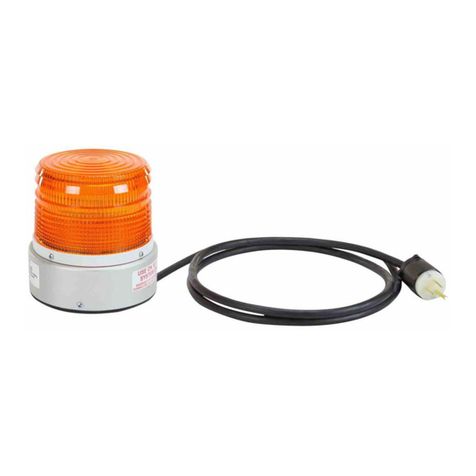
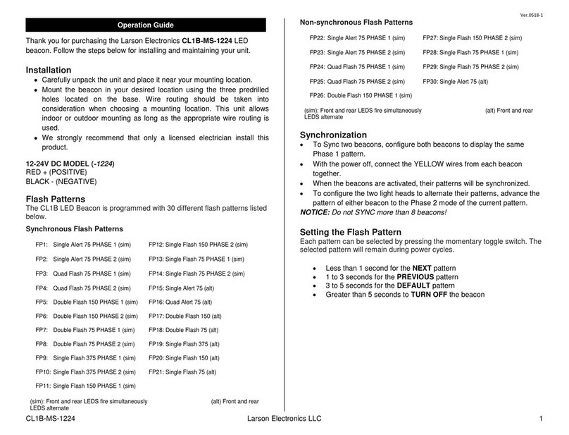
Thank you for purchasing the Larson Electronics CL1B-MS-1227 LED
beacon. Follow thesteps below for installing and maintaining your unit.
Installation
•
Carefully unpack the unit and place it near your mounting location.
•
Mount the beacon in your desired location using the three predrilled
holes located on the base. Wire routing should be taken into
consideration when choosing a mounting location. This unit allows
indoor or outdoor mounting as long as the appropriate wire routing is
used.
•
We strongly recommend that only a licensed electrician install this
product.
Flash Patterns
The CL1B LED Beacon is programmed with 30 different flash patterns listed
below.
Synchronous Flash Patterns
FP1:
Single Alert 75 PHASE 1 (sim)
FP12: Single Flash 150 PHASE 2 (sim)
FP2:
Single Alert 75 PHASE 2 (sim)
FP13: Single Flash 75 PHASE 1 (sim)
FP3:
Quad Flash 75 PHASE 1 (sim)
FP14: Single Flash 75 PHASE 2 (sim)
FP4:
Quad Flash 75 PHASE 2 (sim)
FP15: Single Alert 75 (alt)
FP5:
Double Flash 150 PHASE 1 (sim)
FP16: Quad Alert 75 (alt)
FP6:
Double Flash 150 PHASE 2 (sim)
FP17: Double Flash 150 (alt)
FP7:
Double Flash 75 PHASE 1 (sim)
FP18: Double Flash 75 (alt)
FP8:
Double Flash 75 PHASE 2 (sim)
FP19: Single Flash 375 (alt)
FP9:
Single Flash 375 PHASE 1 (sim)
FP20: Single Flash 150 (alt)
FP10:
Single Flash 375 PHASE 2 (sim)
FP21: Single Flash 75 (alt)
FP11:
Single Flash 150 PHASE 1 (sim)
(sim): Front and rear LEDS fire simultaneously (alt) Front and rear
LEDS alternate
Non-synchronous Flash Patterns
FP22:
Single Alert 75 PHASE 1 (sim)
FP27: Single Flash 150 PHASE 2 (sim)
FP23:
Single Alert 75 PHASE 2 (sim)
FP28: Single Flash 75 PHASE 1 (sim)
FP24:
Quad Flash 75 PHASE 1 (sim)
FP29: Single Flash 75 PHASE 2 (sim)
FP25:
Quad Flash 75 PHASE 2 (sim)
FP30: Single Alert 75 (alt)
FP26:
Double Flash 150 PHASE 1 (sim)
(sim): Front and rear LEDS fire simultaneously (alt) Front and rear
LEDS alternate
Synchronization
•To Sync two beacons, configure both beacons to display the same
Phase 1 pattern.
•With the power off, connect the YELLOW wires from each beacon
together.
•When the beacons are activated, their patterns will be synchronized.
•To configure the two light heads to alternate their patterns, advance the
pattern of either beacon to the Phase 2 mode of the current pattern.
NOTICE: Do not SYNC more than 8 beacons!
Setting the Flash Pattern
Each pattern can be selected by pressing the momentary toggle switch. The
selected pattern will remain during power cycles.
•Less than 1 second for the NEXT pattern
•1 to 3 seconds for the PREVIOUS pattern
•3 to 5 seconds for the DEFAULT pattern
•Greater than 5 seconds to TURN OFF the beacon
Operation Guide
Ver.0518-1
CL1B-MS-1227 Larson Electronics LLC 2
MOTION SENSOR OPERATION
When the motion sensor detects movement, the LED lights are turned on.
Once the motion has stopped, the lights will turn off. Sensitivity, Time
Delay and Lux can be adjusted with their respective control dials on the
motion sensor.
1. The SENSITIVITY setting controls the distance in which the motion
sensor will work. The lowest setting will trigger the motion sensor
when motion is close. The highest setting will trigger the motion
sensor when motion is far.
2. The TIME setting controls how long the unit remains illuminated
following activation & after all motion ceases. The minimum time
(fully anti-clockwise) is approximately 5 seconds and the maximum
time (fully clockwise) is approximately 5 minutes. Set the control to
the desired setting between these limits.
3. The LUX setting determines the level of darkness required for the
unit to start operating. The setting is best achieved by the procedure
below:
Set the LUX control knob fully anti-clockwise. The unit will now start
operating at dusk. If you require the light to activate earlier, wait until the
ambient light level reaches the level of darkness at which you wish the lamp
to become operative, slowly rotate the control in a clockwise direction until a
point is reached where the lamp illuminates. Leave the control set at this
point. At this position, the unit should become operative at approximately the
same level of darkness each evening. Observe the operation of the unit. If
the unit is starting to operate too early (e.g. when it is quite light), adjust the
control slightly anti-clockwise. If the unit starts to operate too late (e.g.
dusk), adjust the control slightly clockwise. Continue to adjust until the unit
operates as desired.
MOTION SENSOR POSITION
The motion sensor’s position can be adjusted by loosening the hand screw
on the side, repositioning, and tightening the hand screw.
9419 US-HWY 175
Kemp, TX 75143 USA
P: 800-369-6671 | INTL: 903-498-3363 F: 903-498-3364
sales@larsonelectronics.com
www.larsonelectronics.com

Other Larson Electronics Security System manuals

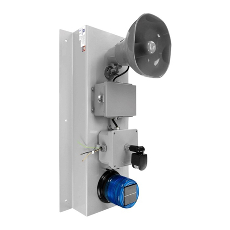
Larson Electronics SLEDB-110V-6C User manual

Larson Electronics

Larson Electronics SLEDB-110V-6C User manual

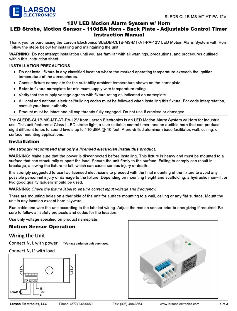
Larson Electronics SLEDB-CL1B-MS-MT-AT-PA-12V User manual

Larson Electronics

Larson Electronics SLEDB-CL1B-MS-MT-AT-PA-12V User manual

Larson Electronics CL1B-MS-1224 User manual

Larson Electronics

Larson Electronics CL1B-MS-1224 User manual

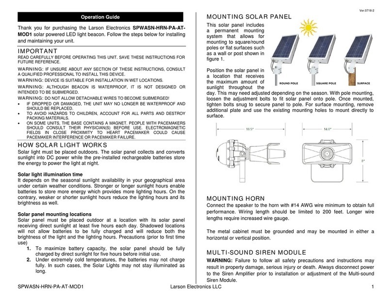
Larson Electronics SPWASN-HRN-PA-ATMOD1 User manual

Larson Electronics

Larson Electronics SPWASN-HRN-PA-ATMOD1 User manual

Larson Electronics SLEDB-110V-MS-PA User manual

Larson Electronics

Larson Electronics SLEDB-110V-MS-PA User manual

Popular Security System manuals by other brands

Motorola hmad8000 quick start guide

Motorola

Motorola hmad8000 quick start guide

Crestron CH-LMD1 Operations & installation guide

Crestron

Crestron CH-LMD1 Operations & installation guide

Telect 009-8005-0404 installation guide

Telect

Telect 009-8005-0404 installation guide

Goscam 8104JM user manual

Goscam

Goscam 8104JM user manual

QNAP NVR VioStor-101 Brochure & specs

QNAP

QNAP NVR VioStor-101 Brochure & specs

Vivago FIDO user manual

Vivago

Vivago FIDO user manual

GIZMO ENGINEERING IS-AB manual

GIZMO ENGINEERING

GIZMO ENGINEERING IS-AB manual

Hills VoiceNav user manual

Hills

Hills VoiceNav user manual

Whelen Engineering Company 72000 Series instructions

Whelen Engineering Company

Whelen Engineering Company 72000 Series instructions

Speaks z wave SSA1 instruction manual

Speaks z wave

Speaks z wave SSA1 instruction manual

DSC PC560 instruction manual

DSC

DSC PC560 instruction manual

GE 4 Series user guide

GE

GE 4 Series user guide

DSC PC1000 instruction manual

DSC

DSC PC1000 instruction manual

Rosslare AuraSys L-4 user manual

Rosslare

Rosslare AuraSys L-4 user manual

M-system AS4V instruction manual

M-system

M-system AS4V instruction manual

Linear REMOTE ACCESS SOFTWARE DVS-1200 installation instructions

Linear

Linear REMOTE ACCESS SOFTWARE DVS-1200 installation instructions

Honeywell System 1500e owner's manual

Honeywell

Honeywell System 1500e owner's manual

Omron ZFX - datasheet

Omron

Omron ZFX - datasheet

manuals.online logo
manuals.online logoBrands
  • About & Mission
  • Contact us
  • Privacy Policy
  • Terms and Conditions

Copyright 2025 Manuals.Online. All Rights Reserved.