Trix 66837 User manual

66837
rot

2
ZH Zusatzfunktion
Auxiliary function
Fonction complémentaire
Extra functie
LR Licht rückwärts
Headlights / marker lights in the rear
Feux arrière
Licht achteruit
LV Licht vorwärts
Headlights / marker lights in the front
Feux avant
Licht vooruit
G2 Gleisanschluss 2
Track connection 2
Connexion voie 2
Railaansluiting 2
G1 Gleisanschluss 1
Track connection 1
Connexion voie 1
Railaansluiting 1
M2 Motoranschluss 2
Motor connection 2
Connexion moteur 2
Motoraansluiting 2
M1 Motoranschluss 1
Motor connection 1
Connexion moteur 1
Motoraansluiting 1
SU SI
ZH
LR
LV
G2
G1
M2
M1
VS
VS Gemeinsamer Rückleiter
Common ground return
Câble de retour commun
Gemeenschappelijke retourleiding

3
Deutsch 4
Funktionen 4
Wartung 4
Einbau 5
Selectrix 8
DCC 11
English 13
Functions 13
Maintenance 13
Installation 14
Selectrix 17
DCC 20
Français 22
Fonctions 22
Maintenance 22
Montage 23
Selectrix 26
DCC 29
Nederlands 31
Werking 31
Onderhoud 31
Inbouw 32
Selectrix 35
DCC 38

4
Funktionen
●Zum wahlweisen Betrieb mit konventionellem
Gleichstrom-Fahrgerät, Trix-Selectrix oder
Digitalsystemen nach NMRA-Norm (DCC).
●Die Betriebsart wird automatisch erkannt.
●Besonders weiches Regelverhalten.
●Besonders ruhiger Motorlauf.
●Verschiedene Regelvarianten zur optimalen
Anpassung an den Motor.
●Intern 127 Fahrstufen.
●Blockstreckenbetrieb mit einfachen Dioden
im Selectrix-Betrieb.
●Kurzschlusssicherung der Motorausgänge.
●Überlastsicherung für Licht und Zusatzfunktion.
●Elektronische Vertauschbarkeit der Anschlüsse.
●Schnittstelle entsprechend NEM 650.
●4-polige SUSI-Schnittstelle zum Anschluss von
bis zu 3 Erweiterungsmodulen im DCC-Betrieb.
Technische Daten
●Maße (L x B, ohne Anschlüsse): 24,2 x 15,4 mm
●Max. Belastung am Motorausgang ≤2,0 A
●Max. Belastung am Lichtausgang ≤300 mA
●Max. Belastung Zusatzfunktion ≤50 mA
●Max. Gesamtbelastung ≤1,0 A
●Funktionsausgang Licht ≤300 mA
●Funktionsausgang Horn ≤50 mA
●Gesamtbelastung einschließlich
SUSI-Schnittstelle ≤2,0 A
Wartung und Pflege
Der Decoder 66837 benötigt keine besondere
Wartung und Pflege. Durch die Steuerung des
Motors mit Impulsen werden jedoch die Wicklungen
und Kohlen des Motors stärker belastet als bei
normalem Gleichstrombetrieb. Aus diesem Grunde
ist eine regelmäßige sorgfältige Pflege des Motors
angezeigt.
Nach spätestens 50 Betriebsstunden sollte das
ganze Lok-Chassis einschließlich Decoder gereinigt
werden. Auch den üblichen Schmierarbeiten sollte
eine gründliche Reinigung vorangehen.

5
Einbau des Decoders
Vor dem Einbau des Decoders ist sicherzustellen,
dass sich die Lok elektrisch und mechanisch in
einwandfreiem Zustand befindet. Mängel oder Ver-
schmutzungen sind unbedingt vor dem Einbau zu
beseitigen. Grundsätzlich sind die Angaben des
Lokherstellers zu beachten.
Zur Vermeidung von Kurzschlüssen muss der
Decoder vor dem Einbau bzw. dem Einstecken in
die Schnittstelle auf der Unterseite mit dem beilie-
genden doppelseitigen Klebeband isoliert werden.
Achten Sie darauf, dass sich auch beim späteren
Fahrbetrieb keine Kurzschlüsse einstellen können.
Achten Sie darauf, dass der eingebaute Decoder in
der Lok nicht mit metallisch leitenden Flächen in
direkten Kontakt kommen kann.
Für Schäden durch nicht fachgerechte Arbeiten
können wir keine Garantie gewähren.
Grundsätzlich darf an dem Decoder nicht gelötet
werden.
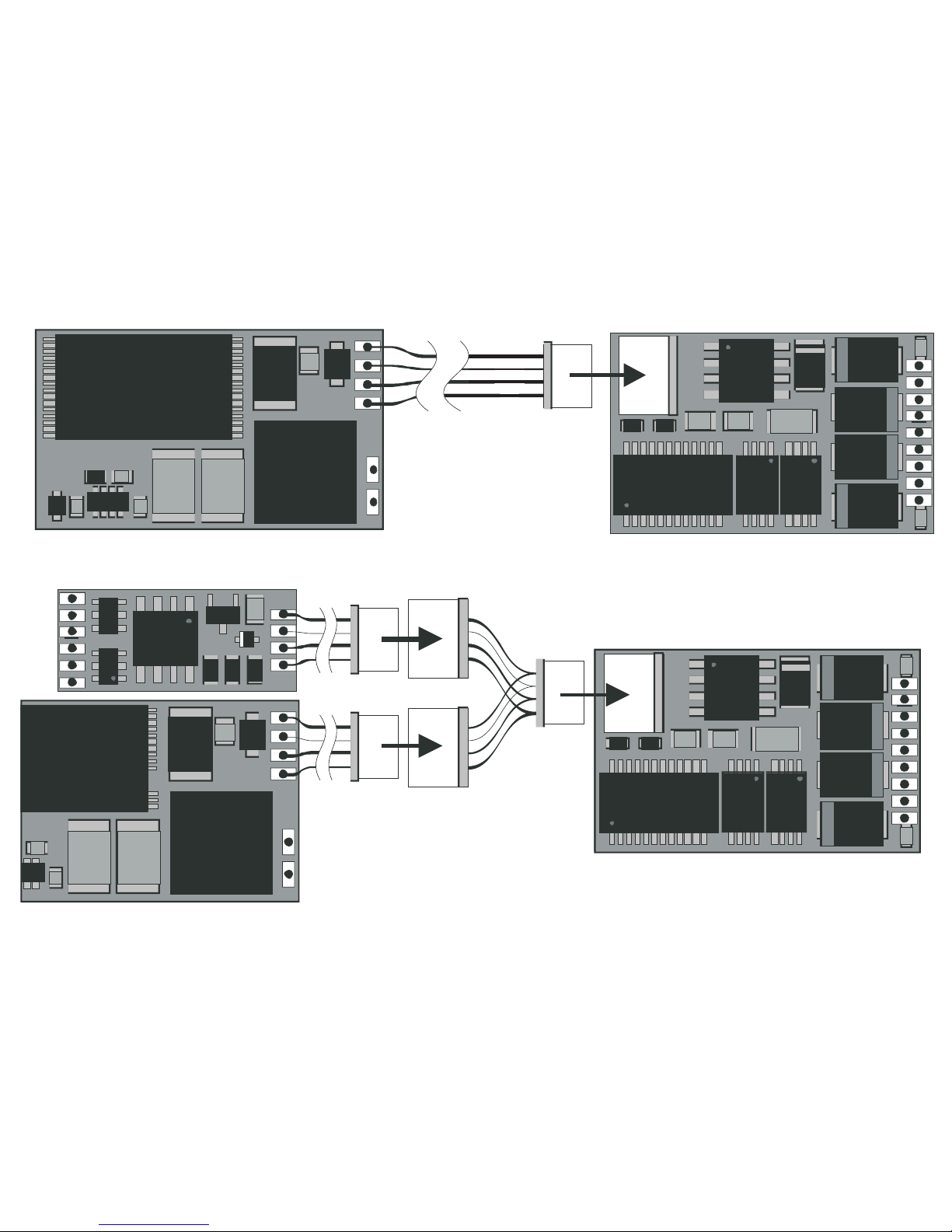
Fahrzeuge mit M-Schnittstelle
Entfernen Sie den in der Lok eingebauten Brücken-
stecker.
Stecken Sie den Decoder-Stecker so ein, dass der
Stift 1 des Steckers in die entsprechende Position
der Lok-Leiterplatte passt. Beachten Sie hierzu
auch die Unterlagen zu Ihrer Lok.
Es dürfen keine Verbindungen zu anderen Drähten
oder Leiterbahnen entstehen!
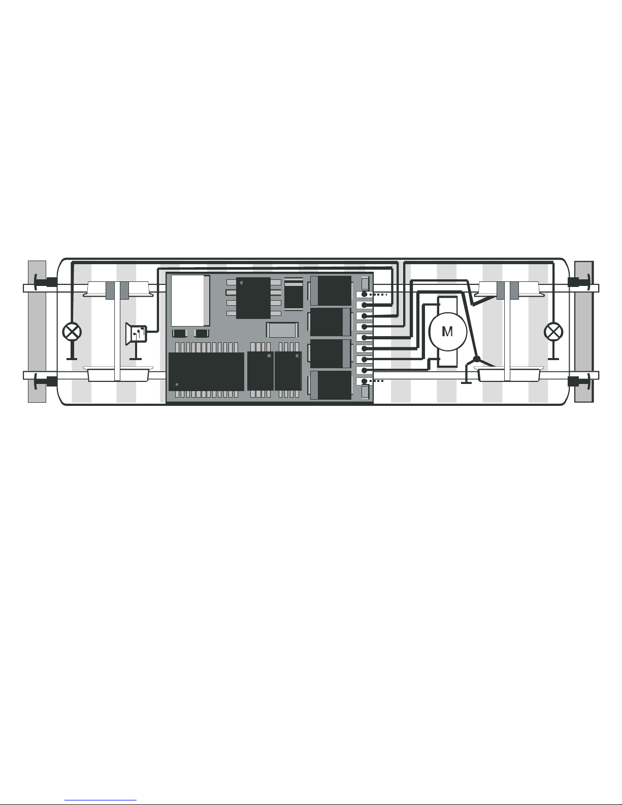
Einbau des Decoders in Fahrzeuge
ohne Schnittstelle
Um Garantieansprüche nicht zu gefährden, empfehlen
wir, den Einbau des Decoders in Loks ohne Schnitt-
stelle durch den autorisierten Fachhandel vornehmen
zu lassen.
Sämtliche Verbindungen zwischen Motor und den
Gleisanschlüssen sind aufzutrennen (Schleifer,
Chassis etc.) Der Motor muß massefrei sein!
Wird eine Verbindung übersehen, kann dies zur
Zerstörung des Decoders führen.
Der darauf folgende elektrische Einbau des Decoders
ist analog zu der abgebildeten Zeichnung (Seite 6)
vorzunehmen. Zuletzt befestigen Sie den Decoder
mit dem mitgelieferten doppelseitigen Klebeband.
Vor der Inbetriebnahme unbedingt nochmals prüfen,
dass der Decoder oder seine Anschlüsse keine
Berührung mit metallisch leitenden Flächen haben.

Einbau des Decoders
Anschluss von Erweiterungsmodulen
An dem Decoder 66837 können über die SUSI-
Schnittstelle bis zu 3 Erweiterungsmodule für weitere
Funktionen angeschlossen werden. Ein Modul kann
über den verdrehsicheren 4-poligen Stecker ange-
schlossen werden. Beim Einsatz mehrerer Module,
sind diese über Y-Kabel oder Abzweigstecker an-
zuschließen. Die SUSI-Schnittstelle wird nur im
DCC-Betrieb unterstützt.
Hinweis:
Um Erweiterungsmodule einstellen (programmieren)
zu können, ist zu beachten, dass hierzu immer nur
ein Modul gleichzeitig eingesteckt sein darf.
Hinweis:
Für Schäden durch nicht fachgerechten Einbau von
Erweiterungsmodulen bzw. durch den Einbau von
falschen oder schadhaften Modulen kann keine
Garantie gewährt werden.
rot
LR
Ho
Gnd
LV
G2
G1
M2
M1
VS
6
Masse
<– Fahrtrichtung 2 (rückwärts) Fahrtrichtung 1 (vorwärts) –>

7

8
Einstellmöglichkeiten Selectrix
●Programmier-Möglichkeiten:
– Fahrzeugadressen 01 ... 111 (03)
– Höchstgeschwindigkeit 1 ... 7 (5)
– Anfahr / Bremsverzögerung (AFB) 1 ... 7 (4)
– Impulsbreite (-dauer) 1 ... 4 (2)
– Signal-Halteabschnitte 1- / 2-teilig (1)
●Erweiterte Einstellungen:
– Vertauschen von Anschlüssen 0 ... 7 (4)
– Wirksamkeit der AFB 1 ... 2 (1)
– Variante der Motorregelung 1 ... 4 (3)
( ) = Werkseitige Voreinstellung.
Hinweis für den Selectrix-Betrieb:
Wird ein eingeschalteter Bremsabschnitt entgegen
der Fahrtrichtung des Bremsabschnittes befahren,
kann je nach Beschaltung des Fahrzeuges das
Fahrlicht ausgehen. Nach dem Bremsabschnitt
schaltet sich das Licht wieder zu.
Selectrix-Betrieb
Stellen Sie die Lok auf das Programmiergleis und
lesen Sie die Einstellwerte des Decoders aus. Die
Grundeinstellung sollte 03-542 sein. Nehmen Sie
die Lok vorübergehend mit diesen Einstellungen
in Betrieb und überprüfen Sie die zur Verfügung
stehenden Funktionen. Nach dieser ersten Kontrolle
können Sie die Parameter der Lok Ihren Bedürfnis-
sen anpassen.
Zeigt das Lesegerät “Lesefehler” an, überprüfen Sie
bitte nochmals die ordnungsgemäße Verdrahtung der
Lok und beachten Sie die Hinweise zum Anschluss
des Programmiergleises. Nehmen Sie die Lok so
auf keinen Fall in Betrieb!

9
Programmierung der Lok (Selectrix)
Sämtliche Parameter der Lok können durch Program-
mierung beliebig oft geändert werden. Die Angaben
zur Programmierung der Standard-Parameter ent-
nehmen Sie bitte den Unterlagen Ihres Programmier-
gerätes. Der Decoder 66837 bietet durch zusätzliche
Parameter die Möglichkeit, sich noch besser an die
speziellen Eigenschaften des jeweiligen Fahrzeuges
anzupassen. Durch die werkseitigen Voreinstellungen
der erweiterten Kennwerte verhält sich der Decoder
entsprechend den bisher verfügbaren Selectrix-
Decodern.
Hinweis:
Die erweiterten Kennwerte des Decoders können mit
dem alten Programmer 56 6841 00 nicht program-
miert werden. Die Programmierung der normalen
Parameter (Adresse etc.) ist ohne Einschränkungen
möglich.
Hinweis:
Das Lesen und Schreiben der erweiterten Kenn-
werte überschreibt die Standard-Kennwerte des
Decoders. Deshalb müssen nach dem Bearbeiten
der erweiterten Kennwerte die Standard-Kennwerte
erneut eingegeben werden.
Lesen der erweiterten Kennwerte
Das Lesen der Werte erfolgt durch Eingabe von
00-111 Programmiertaste
entsprechend Adresse 00
Höchstgeschw. 1
Verzögerung 1
Impulsbreite 1
Stopabschnitte 1
und drücken der Programmiertaste.
Schreiben der erweiterten Kennwerte
Hinweis:
Zum Programmieren der erweiterten Kennwerte
müssen immer 2 Stopabschnitte eingestellt sein!
Das Schreiben der Werte erfolgt durch Eingabe von
00 = VAI Programmiertaste
entsprechend Adresse 00
Höchstgeschw. V (Velo)
Verzögerung A (Acce)
Impulsbreite I (Impw)
Stoppabschnitt 2 (Stop)
und drücken der Programmiertaste.
Die für VAI einzugebenden Werte sind im Folgenden
erklärt:
Hinweis: „Pfeift“ der Motor nach der Inbetriebnahme,
wurde wahrscheinlich vergessen, die Standardwerte
erneut einzugeben.

10
Vertauschen von Anschlüssen (Velo)
Sollten Sie bei einer freien Decoderverdrahtung die
Anschlüsse vertauscht haben, können Sie diese
elektronisch „zurechtrücken“. Kontrollieren Sie
zunächst, welche Anschlüsse vertauscht werden
müssen, und tippen Sie dann die aus der folgenden
Tabelle entnommene Zahl als Wert ein:
Motor Licht Gleis Zahl
xx – 7
–x – 6
x– – 5
– – – 4 (Standard)
xx x 3
–x x 2
x– x 1
–– x 0
Hinweis:
der Vertausch der Anschlüsse für Motor oder Gleis
führt zu entsprechenden Änderungen im Analog-
betrieb.
Wirksamkeit der AFB (Acce)
Hiermit können Sie einstellen, ob die einprogram-
mierte Anfahr / Bremsverzögerung nur in den
(Dioden-) Bremsabschnitten oder immer (auch bei
Steuerung vom Handregler aus) wirksam sein soll.
immer wirksam 1
nur in Halteabschnitten 2
Andere Zahlen sind nicht zulässig.
Variante der Motorregelung (Impw)
Mit diesem Wert können Sie die Regelung optimal
an den Motor anpassen. Es kann keine generelle
Regel angegeben werden, welche Variante das beste
Regelverhalten ergibt. Hier helfen nur Fahrversuche.
sehr hart 1
hart 2
weich 3
sehr weich 4
Vorsicht:
Für Glockenankermotoren ist die Regelvariante 4
zu empfehlen, sowie in der Standardeinstellung die
Impulsbreite 1. Für Beschädigungen an Motoren in
Folge falscher Einstellungen kann keine Garantie
übernommen werden.

11
Einstellmöglichkeiten DCC
– kurze / lange Adresse 01 ... 127 (03)
– 14 / 28 bzw. 128 Fahrstufen (28/128)
– Beschleunigung 1 ... 127 (3)
– Abbremsen 1 ... 127 (3)
– Höchstgeschwindigkeit 1 ... 7 (5)
– Impulsbreite (-dauer) 0 ... 3 (1)
– Variante der Motorregelung 0 ... 3 (2)
– Vertauschen von Anschlüssen 0 ... 7 (0)
Hinweis für den DCC-Betrieb:
Der Betrieb mit gegenpoliger Gleichspannung im
Bremsabschnitt ist mit der werkseitigen Einstellung
nicht möglich. Ist diese Eigenschaft gewünscht, so
muss auf den konventionellen Gleichstorm-Betrieb
verzichtet werden (CV29 / Bit 2 = 0).
Vorsicht:
Für Glockenankermotoren ist die Motorregelvariante 3,
sowie die Impulsbreite 0 zu empfehlen. Für Beschä-
digungen am Motoren in Folge falscher Einstellungen
kann keine Garantie übernommen werden.
DCC-Betrieb
Stellen Sie die Lok auf das Programmiergleis und
lesen Sie die Lokadresse aus. Die Grundeinstellung
sollte 3 sein. Nehmen Sie die Lok vorübergehend
mit dieser Einstellung in Betrieb und überprüfen Sie
die zur Verfügung stehenden Funktionen. Nach die-
ser ersten Kontrolle können Sie die Parameter der
Lok Ihren Bedürfnissen anpassen.
Zeigt das Lesgerät “Lesefehler” an, überprüfen Sie
bitte nochmals die ordnungsgemäße Verdrahtung
der Lok und beachten Sie die Hinweise zum
Anschluss des Programmiergleises. Nehmen Sie die
Lok so auf keinen Fall in Betrieb!
Programmierung der Lok (DCC)
Die Eigenschaften der Lok für DCC-Betrieb können
durch die Programmierung der Configurations-Varia-
blen (CV) beliebig oft geändert werden. Die Pro-
grammierung der CV entnehmen Sie bitte den
Unterlagen Ihres Programmiergerätes.
Hinweis:
Wenn im Decoder andere Fahrstufen programmiert
sind als im Fahrgerät kann es zu Fehlfunktionen
kommen. Die Fahrstufen im Fahrgerät werden nicht
vom Decoder übernommen. Beachten Sie hier auch
die Hinweise zu Ihrem Fahrgerät.

12
CV Bedeutung Wert DCC
1 Adresse 1 – 127
3 Anfahrverzögerung 0 – 127
4 Bremsverzögerung 0 – 127
5 Maximalgeschwindigkeit 1 – 7
17 Erweiterte Adresse (Oberer Teil) CV 29 bit 5 = 1
18 Erweiterte Adresse (Unterer Teil) CV 29 bit 5 = 1
Wert
29 bit 0: Umpolung Fahrtrichtung 0/1 ***
bit 1: Anzahl Fahrstufen 28/128 0/2 0, 1, 2, 3, 4, 5,
bit 2: DCC Betrieb mit Bremsstrecke 6, 7, 32, 34, 35,
DCC-, Selectrix- und Gleichstrombetrieb 0/4 36, 37, 38, 39
bit 5: Adressumfang 7 bit /14 bit 0/32
49 Impulsbreite zur Motorsteuerung 0 – 3
50 Regelvariante 0 – 3
51 bit 0: Motorumpolung 0/1 0 – 7
bit 1: Umpolung Licht 0/2
bit 2: Umpolung Gleis 0/4
*
*
*
*
*
Hinweis: Änderungen der mit gekennzeichneten Einstellungen
in der Betriebsart Selectrix führen automatisch auch zu
Änderungen in der Betriebsart DCC und umgekehrt!
*
Die Werte der gewünschten Einstellungen sind zu addieren.
***

13
Functions
●For optional operation with a conventional
DC power pack, Trix Selectrix, or Digital systems
conforming with the NMRA standards (DCC).
●The mode of operation is automatically recognized.
●Particularly smooth control of running charac-
teristics.
●Particularly quite motor operation.
●Different control variables for optimal adaptation
to the motor.
●127 speed levels internally.
●Block operation with simple diodes in Selectrix
operation.
●Short circuit protection for the motor outputs.
●Overload protection for lights and auxiliary function.
●Electronic interchangeability of the connections.
●NEM 650 connector.
●4-Pole SUSI connector for hooking up to
3 expansion modules in DCC operation.
Technical Specifications
●Dimensions (L x B, without connections)
24.2 x 15.4 mm / 19/20” x 3/5”
●Max. load at the motor outputs ≤2.0 amp
●Max. load at the light outputs ≤300 milliamps
●Max. load for auxiliary function ≤50 milliamps
●Max. total load ≤1.0 amp
●Function output, lights ≤300 milliamps
●Function output, horn ≤50 milliamps
●Total load, including
SUSI connector ≤2.0 amp
Care and Maintenance
The 66837 decoder does not require any special
care and maintenance. Controlling the motor with
pulse width electronics will however create a higher
load for the windings and the brushes for the motor
than with normal DC power operation. For this reason
regular care and maintenance of the motor is a must.
After no more than 50 hours of operation, the entire
locomotive frame including the decoder should be
cleaned. A thorough cleaning should also be done
before the usual lubrication work.

14
Installing the Decoder
Before you install the decoder, you must make sure
that the locomotive is in proper electrical and me-
chanical condition. Defective parts or dirt must be
replaced or removed before you start the installation
process. The specifications of the locomotive’s
manufacturer must be followed explicitly.
To avoid short circuits, the decoder must be insulated
with the double-sided adhesive tape that comes
with it before the latter is installed or plugged into
the connector. When you do this be sure that the
tape is applied in such a way that no short circuits
can occur when running the locomotive later on.
Make sure that the decoder does not come into
direct contact with metal, conductive surfaces after
it has been installed in the locomotive.
The warranty for the decoder cannot be honored
for damages caused by improper work.
No soldering work may be performed on the decoder.
Locomotives with the M Connector
Remove the bridge plug that has been installed in
the locomotive.
Plug the decoder in so that Pin 1 on the plug goes
into the appropriate position on the locomotive
circuit board. Read the documentation for your
locomotive before doing this.
The decoder may not have any connections to
other wires or conductors!
Installing the Decoder
in Locomotives with a Connector
In order not to affect the warranty coverage, we
recommend leaving the installation of the decoder
into locomotives without a connector to an autho-
rized dealer.
All connections between the motor and the con-
nections to the track must be separated (pickups,
frame, etc.). The motor must be free of any ground
connections! If a connection is overlooked, it may
cause the destruction of the decoder.
The electrical installation for the decoder is basically
the same as that shown in the illustration (Page 14).
The last thing to do is to mount the decoder with
the double-side adhesive tape included with the
decoder. Before you run the locomotive for the first
time, you must test to make sure that the decoder
or its connections are not touching any conductive
metal surfaces.

15
Installing the Decoder
Connections for Add-On Modules
Up to 3 add-on modules for additional functions can
be connected to the 66837 decoder by means of
the SUSI connector. A module can be connected
only one way to the 4-pin plug. When using other
modules, the latter must be connected by means
of a Y cable or auxiliary plugs. The SUSI connector
is supported only in DCC operation.
Important:
To set (program) add-on modules, you must
remember that only one module can be plugged in
at any one time for this purpose.
Important:
The warranty will not be honored for damages due
to improper installation of add-on modules or by the
installation of incorrect or damaged modules.
rot
LR
Ho
Gnd
LV
G2
G1
M2
M1
VS
Ground
<– Direction of travel 2 (reverse) Direction of travel 1 (forward) –>

16

17
Possible Selectrix Settings
●Programming Possibilities:
– Locomotive Addresses 01 ... 111 (03)
– Maximum Speed 1 ... 7 (5)
– Acceleration/Braking Delay (AFB) 1 ... 7 (4)
– Pulse Width (Duration) 1 ... 4 (2)
– Signal Braking Block 1 / 2 part (1)
●Additional Settings:
– Swapping Connections 0 ... 7 (4)
– AFB Effectiveness 1 ... 2 (1)
– Variations in Motor Control 1 ... 4 (3)
( ) = Setting done at the factory
Information about Selectrix Operation:
If a locomotive enters a braking block that is on
against the direction of travel for that block, the
headlight(s) for that locomotive may go out depending
on how that locomotive is wired. The headlight(s)
will come back on after leaving the braking block.
Selectrix Operation
Place the locomotive on the programming track
and read out the settings for the decoder. The basic
setting should be 03-542. Temporarily run the loco-
motive with these settings and check out the func-
tions available on the locomotive. After you have
completed this first testing period, you can adapt
the parameters for the locomotive to your needs.
If the reader unit shows “Lesefehler” (“Reader Error”),
check again to make sure that the locomotive is
properly wired and reread the instructions for making
connections to the programming track. In this situa-
tion do not under any circumstances start running
the locomotive on your layout!

18
Programming the Locomotive
(Selectrix)
All of the parameters for the locomotive can be
changed as often as you like by reprogramming the
locomotive. The specifications for programming the
standard parameters can be found in the instructions
for your programming unit. The 66837 decoder has
additional parameters that offer the possibility of
adapting the decoder even more effectively to the
special characteristics of a particular locomotive.
The settings done at the factory for the additional
values will cause the decoder to behave in the same
manner as Selectrix decoders previously available.
Important:
The additional values for the decoder can not be
programmed with the old 56 6841 00 programmer.
The programming of the normal parameters
(address, etc.) can still be done without any limitations.
Important:
The reading and writing of the additional values
overwrites the standard values for the decoder.
The standard values must therefore be entered again
after the additional values have been processed.
Reading the Additional Values
The values are read by entering
00-111 Programming Key
hence Address 00
Max. speed 1
Delay 1
Pulse width 1
Stop area 1
and pressing the programming key.
Writing the Additional Values
Important:
Twp stop areas must always be set for programming
the expanded key values!
The values are written by entering
00 = VAI Programming Key
hence Address 00
Max. speed V (Velo)
Delay A (Acce)
Pulse width I (Impw)
Stop area 2 (Stop)
and pressing the programming key.
Important:
If the motor “whistles” after being placed into service,
you probably forgot to enter the standard values again.
The values to be entered for VAI are explained below:

19
Swapping the Connections (Velo)
If you have mixed up the connections when instal-
ling a decoder in an open wiring situation, you can
“correct” for this electronically. First check which
connections have to be changed, and then enter
the number from the following table as a value:
Motor Light Track Number
xx – 7
–x – 6
x– – 5
– – – 4 (standard)
xx x 3
–x x 2
x– x 1
–– x 0
Important:
Changing the connections for the motor or the
track will result in corresponding changes in analog
operation.
AFB Effectiveness
With this you can set whether the programmed
acceleration / braking delay is only to be effective
in the (diode) braking area or always effective
(even when the hand controller is being used).
always in effect 1
only in stopping areas 2
Other numbers are not permissable.
Variations in Motor Control
With this value you can adapt the control for optimal
operation of the motor. There is no general rule on
which variations result in the best control behavior.
The only thing that can help is to make test runs
of the locomotive.
very hard 1
hard 2
soft 3
very soft 4
Caution:
Control variation 4 is recommended for can motors
with bell-shaped armatures, and in the standard
settings pulse width 1 is also recommended for these
motors. There is no coverage under the warranty for
damages to motors as a result of incorrect settings.

20
Possible DCC Settings
– Short / Long Address 01 ... 127 (03)
– 14 / 28 or 128 Speed Levels (28/128)
– Acceleration 1 ... 127 (3)
– Braking 1 ... 127 (3)
– Maximum Speed 1 ... 7 (5)
– IPulse Width (Duration) 0 ... 3 (1)
– Variations in Motor Control 0 ... 3 (2)
– Swapping Connections 0 ... 7 (0)
Information about DCC Operation:
The setting done at the factory does not permit
operation with opposite polarity DC power in the
braking block. If you want this characteristic, you
must do without conventional DC power operation
(CV29 / Bit 2 = 0).
Caution:
On can motors with bell-shaped armatures, we
recommend values of 3 for the motor control variation
and 0 for the pulse width. The warranty will not
cover damages to the motor caused by incorrect
settings.
DCC Operation
Place the locomotive on the programming track
and read out the settings for the decoder. The basic
setting should be 3. Temporarily run the locomotive
with these settings and check out the functions
available on the locomotive. After you have com-
pleted this first testing period, you can adapt the
parameters for the locomotive to your needs.
If the reader unit shows “Lesefehler” (“Reader Error”),
check again to make sure that the locomotive is
properly wired and reread the instructions for making
connections to the programming track. In this situa-
tion do not under any circumstances start running
the locomotive on your layout!
Programming the Locomotive (DCC)
The characteristics of the locomotive for DCC ope-
ration can be changed as often as you like by pro-
gramming the Configurations Variables (CV). The
specifications for programming the CV values can be
found in the instructions for your programming unit.
Important:
If speed levels are programmed in the decoder,
which are different from those in the locomotive
controller, your system may malfunction. The speed
levels in the locomotive controller are not assumed
by the decoder. In this situation, reread the instruc-
tions for your locomotive controller.
Table of contents
Languages:
Other Trix Media Converter manuals