Trix 66841 User manual

Lokdecoder für 6-polige-NEM-Schnittstelle
66841

2
LR
LV
G2
G1
M2
M1
AUX 1
SUSI V+
SUSI CLK
SUSI DAT
SUSI GND
AUX 2
LR Licht rückwärts
Headlights / marker lights in the rear
Feux arrière
Licht achteruit
LV Licht vorwärts
Headlights / marker lights in the front
Feux avant
Licht vooruit
G2 Gleisanschluss 2
Track connection 2
Connexion voie 2
Railaansluiting 2
G1 Gleisanschluss 1
Track connection 1
Connexion voie 1
Railaansluiting 1
M2 Motoranschluss 2
Motor connection 2
Connexion moteur 2
Motoraansluiting 2
M1 Motoranschluss 1
Motor connection 1
Connexion moteur 1
Motoraansluiting 1

3
D
GB
F
NL
Funktionen 4
Technische Daten 4
Wartung und Pflege 4
Einbau des Decoders 4
Selectrix (Sx1) 5
Selectrix 2 (Sx2) 5
DCC 5
Funktionsmapping 6
Bremsstrecke (CV 27) 6
Fehlerspeicher 6
Temperatursensor 6
Stromüberwachung 7
Sicherheitseinstellung 7
Programmieren der Motorregelung 7
CV- und Parameterliste 8
Vorbelegte Motorregelungs-Einstellungsvarianten 10
Tabelle zum Funktionsmapping 11
Functions 12
Technical Specifications 12
Care and Maintenance 12
Installing the Decoder 12
Selectrix (Sx1) 13
Selectrix 2 (Sx2) 13
DCC 13
Function Mapping 14
Braking Section (CV 27) 14
Error Memory 14
Temperature Sensor 14
Current Monitoring 15
Safety Setting 15
Programming Motor Control 15
CV and Parameter List 16
Motor Control settings variants preset 18
Table for Function Mapping 19
Fonctions 20
Données techniques 20
Maintenance 20
Montage du décodeur 20
Selectrix (Sx1) 21
Selectrix 2 (Sx2) 21
DCC 21
Mappage des fonctions 22
Portion de freinage (CV 27) 22
Mémoire d’erreurs 22
Capteur de température 22
Surveillance du courant 23
Réglage de sécurité 23
Programmation du réglage du moteur 23
Liste CV et de paramètres 24
Variantes de réglage moteur prédéfinies 26
Tableau de mappage de fonctions 27
Werking 28
Technische gegevens 28
Onderhoud 28
Inbouwen van de decoder 28
Selectrix (Sx1) 29
Selectrix 2 (Sx2) 29
DCC 29
Functiemapping 30
Afremtraject (CV 27) 30
Foutgeheugen 30
Temperatuursensor 30
Stroombewaking 31
Beveiligingsinstellingen 31
Programmeren van de motorregeling 31
CV- en parameterlijst 32
Vooringestelde motorregelings-instellingsvarianten 34
Tabel voor functiemapping 35

4
Funktionen
• Zum wahlweisen Betrieb mit konventionellem Gleich-
strom- Fahrgerät, Trix-Selectrix oder Digitalsystemen
nach NMRA-Norm (DCC).
• Keine automatische Systemerkennung zwischen Selec-
trix (SX) und DCC.
Beim ersten Betrieb in einem Digital-System (Selectrix
oder DCC) muss der Decoder auf dieses Digital-System
eingestellt werden. Dazu ist der Decoder ein mal in
diesem Digitalsystem zu programmieren.
• Lichtausgänge dimmbar
• Verschiedene Regelvarianten zur optimalen Anpassung
an den Motor.
• Motorregelung intern mit 1024 Fahrstufen
• Blockstreckenbetrieb mit einfachen Dioden im Selectrix-
Betrieb.
• Überlastsicherung der Motorausgänge.
• Überlastsicherung für Licht und Zusatzfunktion.
• Temperaturüberwachung
• Elektronische Vertauschbarkeit der Anschlüsse.
• Schnittstelle entsprechend NEM 651.
Technische Daten
• Maße (L x B x H, ohne Anschlüsse)
14,2 x 9,3 x 1,8 mm
• Max. Belastung am Motorausgang ≤2,0 A
• Max. Belastung am Lichtausgang ≤200 mA
• Max. Belastung Zusatzfunktion ≤200 mA
• Max. Belastung SUSI ≤1,0 A
• Max. Gesamtbelastung ≤2,0 A
Wartung und Pflege
Der Decoder 66841 benötigt keine besondere Wartung
und Pflege. Durch die Steuerung des Motors mit Impulsen
werden jedoch die Wicklungen und Kohlen des Motors
stärker belastet als bei normalem Gleichstrombetrieb. Aus
diesem Grunde ist eine regelmäßige sorgfältige Pflege des
Motors angezeigt.
Nach spätestens 50 Betriebsstunden sollte das ganze Lok-
Chassis einschließlich Decoder gereinigt werden. Auch den
üblichen Schmierarbeiten sollte eine gründliche Reinigung
vorangehen.
Einbau des Decoders
Vor dem Einbau des Decoders ist sicherzustellen, dass
sich die Lok elektrisch und mechanisch in einwandfreiem
Zustand befindet. Mängel oder Verschmutzungen sind
unbedingt vor dem Einbau zu beseitigen. Grundsätzlich sind
die Angaben des Lokherstellers zu beachten.
Achten Sie darauf, dass sich beim Einbau und auch beim
späteren Fahrbetrieb keine Kurzschlüsse ergeben können.
Evtl. muss der Decoder vor dem Einbau mit einem Schrumpf-
schlauch isoliert werden.
Für Schäden durch nicht fachgerechte Arbeiten können wir
keine Garantie gewähren.

5
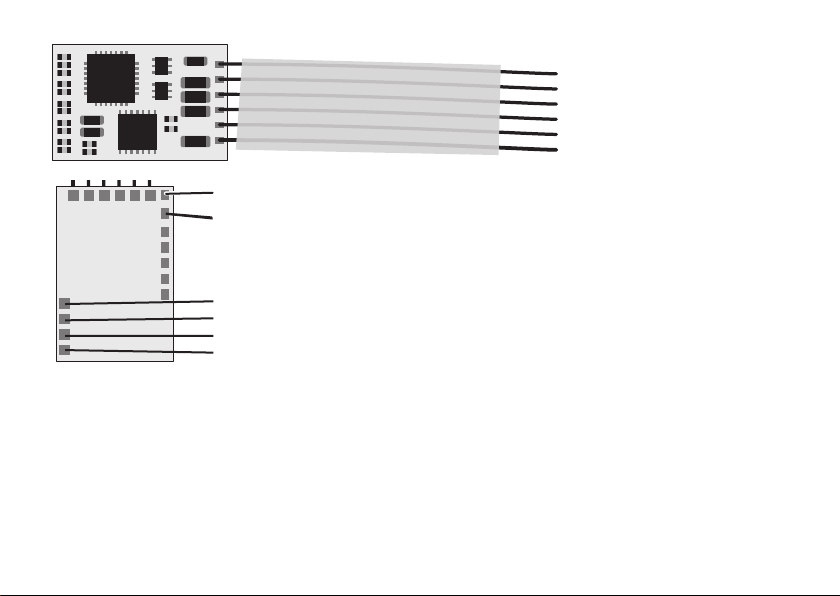
Fahrzeuge mit S-Schnittstelle
Entfernen Sie die in der Lok eingebaute Steckerplatine.
Kürzen Sie die Anschlussdrähte des Decoders auf eine Län-
ge von ca. 5 mm – 10 mm und entfernen Sie die Isolierung.
Stecken Sie den Decoder, falls vom Hersteller der Lok nicht
anders vermerkt, mit den Bauteilen nach oben in die Schnitt-
stelle. Die Anschlussdrähte sollten gerade eingesteckt wer-
den und müssen eventuell anschließend leicht abgewinkelt
werden. Es dürfen keine Verbindungen zu anderen Drähten
oder Leiterbahnen entstehen!
Einbau des Decoders in Fahrzeuge ohne Schnittstelle
Um Garantieansprüche nicht zu gefährden, empfehlen wir,
den Einbau des Decoders in Loks ohne Schnittstelle durch
den autorisierten Fachhandel vornehmen zu lassen.
Sämtliche Verbindungen zwischen Motor und den Gleisan-
schlüssen sind aufzutrennen (Schleifer, Chassis etc.) Der
Motor muß massefrei sein! Wird eine Verbindung überse-
hen, kann dies zur Zerstörung des Decoders führen.
Vor der Inbetriebnahme unbedingt nochmals prüfen, dass
der Decoder oder seine Anschlüsse keine Berührung mit
metallisch leitenden Flächen haben.
Selectrix (Sx1)
Die von Sx1 unterstützten Parameter können durch
Programmieren beliebig oft geändert werden. Die Angaben
zum Programmieren der Standard-Parameter sowie der
erweiterten Parameter entnehmen Sie bitte den Unterlagen
Ihres Programmiergerätes.
Werkseinstellung der Standard-Parameter:
01-542
Werkseinstellung der erweiterten Parameter
00-413
Hinweis:
Das Lesen und Schreiben der erweiterten Kennwerte über-
schreibt die Standard-Kennwerte des Decoders. Deshalb
müssen nach dem Bearbeiten der erweiterten Kennwerte
die Standard-Kennwerte erneut eingegeben werden.
Selectrix 2 (Sx2)
Die Eigenschaften der Lok für Sx2-Betrieb können durch die
Programmierung der Parametern (PAR) beliebig oft geändert
werden. Angaben zur Programmierung der Parameter ent-
nehmen Sie bitte den Unterlagen Ihres Programmiergerätes.
Beachten Sie hierzu auch die Parameter-Tabelle auf Seite 8.
DCC
Die Eigenschaften der Lok für DCC-Betrieb können durch die
Programmierung der Configurations Variablen (CV) beliebig
oft geändert werden. Angabe zur Programmierung der CV
entnehmen Sie bitte den Unterlagen Ihres Programmierge-
rätes. Beachten Sie hierzu auch die CV-Tabelle auf Seite 8.

6
Funktionsmapping
Die Funktionen F0 – F16 können über die CV 33 – 50
(PAR 061 – 078) frei gemappt werden.
Beachten Sie hierzu die Tabelle auf S 11.
Beispiele fürs Funktionsmapping:
Auf F5 soll AUX2 schaltbar sein
-> CV 39 (PAR 067) auf den Wert 1 programmieren
Auf F7 soll LR, LV und der Rangiergang schaltbar sein
-> CV 41 (PAR 069) auf den Wert w(64 + 32 + 16) = 112 pro-
grammieren
Bremsstrecke (CV 27)
Für die Auslösung der Bremsstrecken sind folgende Mög-
lichkeiten einstellbar:
Bit 0: Bremsen mit asym. Digitalspannung auf linkem Gleis
Bit 1: Bremsen mit asym. Digitalspannung auf rechtem Gleis
Bit 4: Bremsen mit gegenpoliger Gleichspannung
Bit 5: Bremsen mit gleichpoliger Gleichspannung
Bit 6: Bremsen mit Diode im rechten Gleis
Bit 7: Bremsen mit Diode im linken Gleis
Weitere Einstellungen zur Bremsstrecke können mit den
CV 121 (PAR 021), CV 122 (PAR 022) und CV 123 (AR 023)
programmiert werden. Beachten Sie hierzu die CV-Tabelle
ab Seite 8
Fehlerspeicher
Der Decoder erkennt zu hohen Stromverbrauch oder zu
hohe Temperaturen und legt einen entsprechenden Wert im
CV 30 / PAR 030 ab. Der Decoder zeigt dies durch blinkende
Stirnbeleuchtungen so lange, bis der Fehlerspeicher durch
einen beliebigen Wert überschrieben wird. So wird ein Feh-
ler auch dann sichtbar, wenn er in einem nicht sichtbaren
Anlagenbereich aufgetreten ist.
Bit 0 Wert 1 Übertemperatur
Bit 1 Wert 2 Überstrom Motor
Bit 2 Wert 4 Überstrom Funktionsausgänge
Bit 3 Wert 8 Kurzschluss Motor gegen Gleis
Bit 7 Wert 128 allg. Motorfehler (z.B. Blockade)
Temperatursensor
Der eingebaute Temperatursensor arbeitet im Messbereich
von 0 – 85° C. Um eine korrekte Funktionsweise zu ermögli-
chen, muss der Sensor einmalig kalibriert werden. Dazu die
Lok mit Decoder für ca. 20 Minuten stehen lassen, bis der
Decoder die Umgebungstemperatur angenommen hat und
im Anschluss in der CV137 (PAR 117) die aktuelle Raumtem-
peratur in °C einstellen.
Bei Überschreiten der in CV 118 (PAR 138) eingestellten
Temperatur wird die Lok anhalten und erst nach entspre-
chender Abkühlung wieder mit den eingestellten Geschwin-
digkeit weiterfahren. Zudem wird im Fehlerspeicher im Bit 0
der Wert 1 gesetzt.
deutsch

7
Stromüberwachung
Der Decoder kann den Stromverbrauch von Motor und
Funktionsausgängen überwachen. Der zulässige Verbrauch
des Motors ist mit der CV 139 (PAR 119) zwischen 10 mA
(Wert 1) und 2550 mA (Wert 255) einstellbar. Wird der einge-
stellte Motorstrom überschritten, wird die Lok sofort abge-
schaltet und im Fehlerspeicher im Bit 1 der Wert 2 gesetzt.
Die Funktionsausgänge werden gemeinsam überwacht. Bei
Überlast werden alle Funktionsausgänge abgeschaltet und
im Fehlerspeicher im Bit 2 der Wert 4 gesetzt.
Sicherheitseinstellung
Der Temperatursensor und die Stromüberwachung können
im CV 130 (PAR 96) gesondert ein- und ausgeschaltet
werden.
Bit 0 Wert 1 Temperaturüberwachung
Bit 1 Wert 2 Stromüberwachung Motor
Bit 2 Wert 4 Stromüberwachung LV, LR, AUX1, AUX2
Bit 3 Wert 8 Kurzschluss Motor gegen Gleis
Bit 7 Wert 128 erweiterte Motorüberwachung
Programmieren der Motorregelung
Der nachfolgend beschriebene Ablauf sollte in aller Regel
eine optimale Regelungs-Einstellung ergeben. Grundlage
ist die Werkseinstellung des Decoders. Wir empfehlen die
Regelungseinstellungen auf dem Hauptgleis vorzunehmen
(PoM) damit die Änderungen jeweils sofort erkennbar
werden.
1. Lok mit Fahrstufe 1 fahren
2. CV 65 so einstellen, dass die Lok nicht ruckelt. Der Motor
sollte eine konstante Drehzahl erreichen.
3. Bei zu hoher Geschwindigkeit schrittweise den Wert in
CV 10 erhöhen.
4. Bei zu niedriger Geschwindigkeit schrittweise den Wert
in CV 2 erhöhen.
5. Wert in CV 5 auf 127 einstellen.
6. Lok mit Fahrstufen 126 fahren.
7. Wert in CV 112 so einstellen, dass die Lok möglichst
schnell fährt, allerdings darf kein Ruckeln aufkommen.
8. Mit CV 5 den die gewünschte Höchstgeschwindigkeit
einstellen.
In dem Decoder sind 4 Einstellungsvarianten (Preset)
vorbelegt und können über die CV 160 (PAR 050) eingestellt
werden (siehe Tabelle auf Seite 10).

8
CV- und Parameterliste
CV PAR Bezeichnung Bereich Wert Bemerkung
1 — kurze Adresse (7 Bit) 0 – 127 3
2 014 Minimalgeschindigkeit 0 – 255 1
3 011 Anfahrverzögerung 0 – 255 5
4 012 Bremsverzögerung 0 – 255 5
5 013 Maximalgeschwindigkeit 0 – 127 92
8 101 Reset CV 8 = 8; PAR 101 = 101
9 054 PWM-Frequenz 0 / 1 0 0 = 32 kHz; 1 = 16 kHz
10 010 Max. Messzeit in ms 0 – 63 12
13 046 F1 – F8 im Analogbetrieb 0 – 255 0
14 047 F9 – F14 und Licht im Analogbetrieb 0 – 255 3
17 lange Adresse (14 Bit), oberes Byte 192 – 231 195
18 lange Adresse (14 Bit), unteres Byte 0 – 255 242
19 Traktionsadresse 0 – 127 0
21 048 F1 – F8 bei Traktion 0 – 255 0
22 049 F9 – F14 und Licht bei Traktion 0 – 255 0
27 DCC Bremsbetrieb 0 – 63 18
29 045
Bit 0: Umpolung Fahrtrichtung
Bit 1: Anzahl Fahrstufen 14 oder 28/128 *
Bit 2: DCC Betrieb mit Bremsstrecke
Bit 5: Adressumfang 7 Bit / 14 Bit
6
30 030 Fehlerspeicher 0 1 = Übertemperatur
2 = zu hoher Stromverbrauch
33 061 Funktionsmapping F0, LV 0 – 255 1

9
CV PAR Bezeichnung Bereich Wert Bemerkung
34 062 Funktionsmapping F0, LR 0 – 255 2
35 063 Funktionsmapping AUX 1 0 – 255 4
36 064 Funktionsmapping AUX 2 0 – 255 8
37 065 Funktionsmapping AUX 3 0 – 255 0
38 066 Funktionsmapping Rangiergang 0 – 255 16
39 067 Funktionsmapping AUX 4 0 – 255 0
40 – 50 068 –
078 Funktionsmapping F6 – F16
52 081 Dimmung Licht 0 – 255 255
54 083 Dimmung AUX 1 0 – 255 255
55 084 Dimmung AUX 2 0 – 255 255
64 097 Anfahrspannung analog 0 – 255 0
65 025 Kickstart 0 – 255 96
112 034 Messreferenz 1 – 31 24
113 051 Kennlinie 0 – 7 5 0 = linear, 7 = max. durchhängend
114 053 Impulsbreite in ms 0 – 255 8
115 052 Dämpfung 0 – 7 3
116 056 Ansprechverhalten 0 – 11 6
119 017 Maximalgeschwindigkeit analog 2 – 255 255
120 016 Anfahrverzögerung von FS0 auf FS1 0 – 255 1
121 021 Halteabschnitte 0 / 1 0 ein- oder zweiteilig
122 022 Geschw. in 2-teiligen Bremsabschnitt 0 – 127 32
123 023 Bremszeit in Halteabschnitten 0 – 255 5

10
CV PAR Bezeichnung Bereich Wert Bemerkung
130 096 Sicherheitseinstellungen 0 – 255 142
132 099 Mindestgeschwindigkeit analog 0 – 255 128
133 100 Mindestspannung analog 0 – 255 0
134 114 Dimmung Licht analog 0 – 255 128
135 115 Dimmung AUX 1 analog 0 – 255 128
136 116 Dimmung AUX 2 analog 0 – 255 128
137 117 Temperatursensor 0 – 85
138 118 Abschalttemperatur 0 – 85 80
139 119 Stromüberwachung 0 – 255 100 Wert * 10 = Grenzwert in mA
001 lange Adresse, 10‘er / 1‘er Stellen 0 – 99 0
002 lange Adresse, 1000‘er / 100‘er Stellen 0 – 99 0
003 kurze Adresse 0 – 112 1
007 Wirkungsweise Funktionsadresse 0 – 3 0
008 Traktionsadresse, 10‘er / 1‘er Stellen 0 – 99 1
009 Traktionsadresse, 1000‘er / 100‘er Stellen 0 – 99 10
160 050 Motorregelungs-Preset (Regelvariante) 0 – 3 2
Vorbelegte Motorregelungs-Einstellungsvarianten
Variante,
CV 160 (PAR 050) Max. Messzeit
CV 10 (PAR 010) Kickstart
CV 65 (PAR 25) Dämpfung
CV 115 (PAR 52) Ansprechverhalten
CV 116 (PAR 56)
0 6 32 1 4
1 8 64 2 5
2 12 96 3 6
3 24 128 4 8

11
Tabelle zum Funktionsmapping
F ? CV PAR Rangierg. AUX 4 AUX 3 AUX 2 AUX 1 LR LV
F0 / LV 33 061 128 32 16 8 4 2 1
F0 / LR 34 062 128 32 16 8 4 2 1
F1 35 063 128 32 16 8 4 2 1
F2 36 064 128 32 16 8 4 2 1
F3 37 065 128 32 16 8 4 2 1
F4 38 066 16 4 2 1 128 64 32
F5 39 067 16 4 2 1 128 64 32
F6 40 068 16 4 2 1 128 64 32
F7 41 069 16 4 2 1 128 64 32
F8 42 070 16 4 2 1 128 64 32
F9 43 071 2 128 64 32 16 8 4
F10 44 072 2 128 64 32 16 8 4
F11 45 073 2 128 64 32 16 8 4
F12 46 074 2 128 64 32 16 8 4
F13 47 075 2 128 64 32 16 8 4
F14 48 076 2 128 64 32 16 8 4
F15 49 077 2 128 64 32 16 8 4
F16 50 078 2 128 64 32 16 8 4

12
Functions
• For optional operation with a conventional DC locomotive
controller, Trix Selectrix, or digital systems adhering to
the NMRA standard (DCC).
• No automatic system recognition between Selectrix (SX)
and DCC.
When operating for the first time in a digital system
(Selectrix or DCC) the decoder must be set for this digital
system. To do that, the decoder must be programmed
once in that digital system.
• Lighting outputs can be dimmed
• Different control variations for optimal adaptation of the
motor.
• Motor control internally with 1,024 speed levels
• Block route operation with simple diodes in Selectrix
operation.
• Overload protection of the motor outputs.
• Overload protection for light and auxiliary functions.
• Temperature monitoring
• Electronic interchangeability of the connections.
• Interface corresponds to NEM 651.
Technical Specifications
• Dimensions (L x B x H, without connections)
14,2 x 9,3 x 1,8 mm
• Max. load at the motor outputs ≤2,0 A
• Max. load at the light outputs ≤200 mA
• Max. load for auxiliary function ≤200 mA
• Max. load for SUSI ≤1,0 A
• Max. total load ≤2,0 A
Care and Maintenance
The 66841 decoder does not require any special care and
maintenance. Controlling the motor with pulse width elec-
tronics will however create a higher load for the windings
and the brushes for the motor than with normal DC power
operation. For this reason regular care and maintenance of
the motor is a must.
After no more than 50 hours of operation, the entire
locomotive frame including the decoder should be cleaned.
A thorough cleaning should also be done before the usual
lubrication work.
Installing the Decoder
Before you install the decoder, you must make sure that the
locomotive is in proper electrical and mechanical condition.
Defective parts or dirt must be replaced or removed before
you start the installation process. The specifications of the
locomotive’s manufacturer must be followed explicitly.
To avoid short circuits, the decoder must be insulated with
the double-sided adhesive tape that comes with it before the
latter is installed or plugged into the connector. When you
do this be sure that the tape is applied in such a way that no
short circuits can occur when running the locomotive later
on. The warranty for the decoder cannot be honored for
damages caused by improper work.
The auxiliary function should be connected only by an
authorized Trix dealer.

13
Locomotives with the S Connector
Remove the plug-in circuit board originally installed in
the locomotive.
Shorten the connection wires for the decoder to a length of
approximately 5 mm / 1/4“ and remove the insulation.
Plug the decoder into the connector with the components
facing up, unless there are other directions from the manuf-
acturer of the locomotive. The connecting wires should be
plugged in straight and may have to be bent slightly after
being plugged into the connector. These connecting wires
must not be allowed to come into contact with other wires
or conductors!
Installing the Decoder in Locomotives with a Connector
In order not to affect the warranty coverage, we recommend
leaving the installation of the decoder into locomotives
without a connector to an authorized dealer.
All connections between the motor and the connections to
the track must be separated (pickups, frame, etc.). The mo-
tor must be free of any ground connections! If a connection
is overlooked, it may cause the destruction of the decoder.
The last thing to do is to mount the decoder with the double-
side adhesive tape included with the decoder. Before you
run the locomotive for the first time, you must test to make
sure that the decoder or its connections are not touching
any conductive metal surfaces.
Selectrix (Sx1)
The parameters supported by Sx1 can be changed as often
as desired with programming. The details for programming
standard parameters as well as advanced parameters can
be found in the documentation for your programming device.
Factory setting for standard parameters:
01-542
Factory setting for advanced parameters:
00-413
Note:
Reading and writing advanced parameters overwrites the
standard parameters for the decoder. The standard parame-
ters must therefore be entered again after editing advanced
parameters.
Selectrix 2 (Sx2)
The characteristics for the locomotive for Sx2 operation
can be changed as often as desired by programming the
parameters (PAR). Details for programming the parameters
can be found in the documentation for your programming
device. Please note the parameter table on Page 16 when
doing this.
DCC
The characteristics for the locomotive for DCC operation
can be changed as often as desired by programming the
Configuration Variables (CV). Details for programming the
CVs can be found in the documentation for your program-
ming device. Please note the CV table on Page 16 when
doing this.

14
Function Mapping
The functions F0 – F16 can be mapped freely be means of
CV 33 – 50
(PAR 061 – 078).
When doing this, note the table on Page 19.
Examples for function mapping:
AUX2 is to be controlled at F5
-> Program CV 39 (PAR 067) to Value 1
LR, LV and the switching range are to be controlled at F7
-> Program CV 41 (PAR 069) to the value (64 + 32 + 16) = 112
Braking Section (CV 27)
The following possibilities can be set for activating braking
sections:
Bit 0: Braking with asymmetrical digital voltage in the left rail
Bit 1: Braking with asymmetrical digital voltage in the right
rail
Bit 4: Braking with opposed polarity DC voltage
Bit 5: Braking with equal polarity DC voltage
Bit 6: Braking with a diode in the right rail
Bit 7: Braking with a diode in the left rail
Additional adjustments to a braking section can be program-
med with CV 121 (PAR 021), CV 122 (PAR 022), and CV 123 (AR
023). When doing this, note the CV table starting on Page 16.
Error Memory
The decoder recognizes too high a current consumption or
too high temperatures and archives a corresponding value
in CV 30 / PAR 030. The decoder shows this with blinking
headlights until the error memory is overwritten by any
value. An error thus becomes visible if it occurs in a part of
the layout not visible.
Bit 0 Value 1 Excess temperature
Bit 1 Value 2 Excess current, motor
Bit 2 Value 4 Excess current, function outputs
Bit 3 Value 8 Short circuit of motor versus track
Bit 7 Value 128 Misc. motor errors (ex. blockage)
Temperature Sensor
The built-in temperature sensor works in a measurement
range of 0° – 85° C / 32° - 185° F. The sensor must be calibra-
ted once in order to enable correct function. To do this, let
the locomotive with the decoder stand for about 20 minutes
until the decoder has accepted the environment tempera-
ture and has set the current surrounding temperature in °C
in conjunction with CV137 (PAR 117).
When overwriting the temperature set in CV 118 (PAR 138),
the locomotive will come to a halt and will not go further
with the speed set until it has cooled off accordingly. In
addition, Value 1 will be set in the error memory in Bit 0.

15
Current Monitoring
The decoder can monitor the current consumption of the
motor and the function outputs. The permissible consumpti-
on for the motor can be set with CV 139 (PAR 119) between
10 milliamps (Value 1) and 2,550 milliamps (Value 255). If the
current that has been set is exceeded, the locomotive is im-
mediately turned off and Value 2 is set in the error memory
in Bit 1. The function outputs are monitored jointly. In the
event of an overload, all function outputs are turned off and
Value 4 is set in Bit 2.
Safety Setting
The temperature sensor and the current monitoring can be
turned on and off separately in CV 130 (PAR 96).
Bit 0 Value 1 Temperature monitoring
Bit 1 Value 2 Current monitoring, motor
Bit 2 Value 4 Current monitoring, LV, LR, AUX1, AUX2
Bit 3 Value 8 Short circuit of motor versus track
Bit 7 Value 128 Advanced motor monitoring
Programming Motor Control
As a rule, the procedure described below should give an
optimal control setting. The basis is the factory settings for
the decoder. We recommend doing the control settings on
the main track (PoM) so that any changes are immediately
recognizable.
1. Run the locomotive at Speed Level 1
2. Set CV 65 so that the locomotive does not stutter. The
motor should reach a constant rpm.
3. In the event of too high a speed, increase the value in CV
10 in steps.
4. In the event of too low a speed, increase the value in CV 2
in steps.
5. Set the value in CV 5 at 127.
6. Run the locomotive at Speed Level 126.
7. Set the value in CV 112 so that the locomotive runs as fast
as possible. However, no stuttering may be allowed to
occur.
8. Then set the desired maximum speed with CV 5.
There are 4 settings variants preset in the decoder, and they
can be set by means of CV 160 (PAR 050)
(see table on Page 18).

16
CV and Parameter List
CV PAR Description Range Value Notes
1 — Short address (7 bits) 0 – 127 3
2 014 Minimum speed 0 – 255 1
3 011 Acceleration delay 0 – 255 5
4 012 Braking delay 0 – 255 5
5 013 Maximum speed 0 – 127 92
8 101 Reset CV 8 = 8; PAR 101 = 101
9 054 PWM frequency 0 / 1 0 0 = 32 kHz; 1 = 16 kHz
10 010 Max. measurement period in milliseconds 0 – 63 12
13 046 F1 – F8 in analog operation 0 – 255 0
14 047 F9 – F14 and lighting in analog operation 0 – 255 3
17 Long address (14 bits), upper byte 192 – 231 195
18 Long address (14 bits), lower byte 0 – 255 242
19 M.U. address 0 – 127 0
21 048 F1 – F8 with M.U. 0 – 255 0
22 049 F9 – F14 and lighting with M.U. 0 – 255 0
27 DCC braking operation 0 – 63 18
29 045
Bit 0: Polarity reversal, direction
Bit 1: Number of speed levels 14 or 28/128 *
Bit 2: DCC operation with braking section
Bit 5: Address length 7 bits / 14 bits
6
30 030 Error memory 0 1 = Excess temperature
2 = too high current consumption
33 061 Function mapping F0, LV 0 – 255 1

17
CV PAR Description Range Value Notes
34 062 Function mapping, F0, LR 0 – 255 2
35 063 Function mapping, AUX 1 0 – 255 4
36 064 Function mapping, AUX 2 0 – 255 8
37 065 Function mapping, AUX 3 0 – 255 0
38 066 Function mapping, switching range 0 – 255 16
39 067 Function mapping, AUX 4 0 – 255 0
40 – 50 068 –
078 Function mapping, F6 – F16
52 081 Dimming, lighting 0 – 255 255
54 083 Dimming, AUX 1 0 – 255 255
55 084 Dimming, AUX 2 0 – 255 255
64 097 Starting voltage, analog 0 – 255 0
65 025 Kick start 0 – 255 96
112 034 Measurement Reference 1 – 31 24
113 051 Response curve 0 – 7 5 0 = linear,
7 = max. dipping
114 053 Pulse width in milliseconds 0 – 255 8
115 052 Damping action 0 – 7 3
116 056 Response behavior 0 – 11 6
119 017 Maximum speed, analog 2 – 255 255
120 016 Acceleration delay from FS0 to FS1 0 – 255 1
121 021 Stopping section 0 / 1 0 One or two-part
122 022 Speed in a 2-part braking section 0 – 127 32
123 023 Braking time in stopping sections 0 – 255 5

18
CV PAR Description Range Value Notes
130 096 Safety settings 0 – 255 142
132 099 Minimum speed, analog 0 – 255 128
133 100 Minimum voltage, analog 0 – 255 0
134 114 Dimming, lighting, analog 0 – 255 128
135 115 Dimming, AUX 1, analog 0 – 255 128
136 116 Dimming, AUX 2, analog 0 – 255 128
137 117 Temperature sensor 0 – 85
138 118 Shutoff temperature 0 – 85 80
139 119 Current monitoring 0 – 255 100 Value * 10 = safety value in milliamps
001 Long address, 10th / 1st placeholders 0 – 99 0
002 Long address, 1,000th / 100th placeholders 0 – 99 0
003 Short address 0 – 112 1
007
Mode of Operation for the Function Address
0 – 3 0
008 M.U. address, 10th / 1st placeholders 0 – 99 1
009 M.U. address, 1,000th / 100th placeholders 0 – 99 10
160 050 Motor control preset (control variants) 0 – 3 2
Motor Control settings variants preset
Variants,
CV 160 (PAR 050) Max. Measurement Time
CV 10 (PAR 010) Kickstart
CV 65 (PAR 25) Damping Action
CV 115 (PAR 52) Response Behavior
CV 116 (PAR 56)
0 6 32 1 4
1 8 64 2 5
2 12 96 3 6
3 24 128 4 8

19
Table for Function Mapping
F ? CV PAR Rangierg. AUX 4 AUX 3 AUX 2 AUX 1 LR LV
F0 / LV 33 061 128 32 16 8 4 2 1
F0 / LR 34 062 128 32 16 8 4 2 1
F1 35 063 128 32 16 8 4 2 1
F2 36 064 128 32 16 8 4 2 1
F3 37 065 128 32 16 8 4 2 1
F4 38 066 16 4 2 1 128 64 32
F5 39 067 16 4 2 1 128 64 32
F6 40 068 16 4 2 1 128 64 32
F7 41 069 16 4 2 1 128 64 32
F8 42 070 16 4 2 1 128 64 32
F9 43 071 2 128 64 32 16 8 4
F10 44 072 2 128 64 32 16 8 4
F11 45 073 2 128 64 32 16 8 4
F12 46 074 2 128 64 32 16 8 4
F13 47 075 2 128 64 32 16 8 4
F14 48 076 2 128 64 32 16 8 4
F15 49 077 2 128 64 32 16 8 4
F16 50 078 2 128 64 32 16 8 4

20
Fonctions
• Pour l’exploitation au choix conventionnelle en courant
continu (DCC), Trix-Selectrix ou avec des systèmes
numériques répondant à la norme NMRA (DCC).
• Aucune détection système automatique entre Selectrix
(SX) et DCC. À la première mise en service dans un système
numérique (Selectrix ou DCC), le décodeur doit être réglé
sur ce système numérique. Pour cela, le décodeur doit être
programmé une fois dans ce système numérique.
• Sorties lumineuses graduables
• Différentes variantes de réglage pour une adaptation
optimale au moteur.
• Réglage interne du moteur avec 1024 régimes
• Cantonnement avec diodes simples en mode Selectrix.
• Protection contre les surcharges des sorties moteur.
• Protection contre les surcharges pour l’éclairage et la
fonction supplémentaire.
• Surveillance de la température
• Possibilité d’échange électronique des raccordements.
• Interface correspondant à NEM 651.
Données techniques
• Dimensions (L x La x B, sans les connexions)
14,2 x 9,3 x 1,8 mm
• Charge maximale aux sorties moteur≤2,0 A
• Charge maximale aux sorties feux ≤200 mA
• Charge maximale aux sorties fonction
complémentaire ≤200 mA
• Charge maximale aux sorties SUSI ≤1,0 A
• Charge maximale totale ≤2,0 A
Maintenance
Le décodeur 66841 ne nécessite aucun entretien particu-
lier. Du fait de la commande du moteur par impulsions, les
enroulements et les balais du moteur sont cependant plus
fortement sollicités que lors d’une exploitation normale en
courant continu. Compte tenu de cela, un entretien soigneux
du moteur est requis à intervalles réguliers.
Toutes les 50 heures de fonctionnement, il est requis de pro-
céder à un nettoyage en règle de la totalité du mécanisme
d’entraînement y compris le décodeur. Un nettoyage métho-
dique doit précéder toute opération de graissage usuelle.
Montage du décodeur
Avant de procéder au montage du décodeur, assurezvous
que la locomotive est en état de fonctionnement tant
électrique que mécanique. Il faut impérativement remédier
à tout défaut ou encrassement avant de monter le décodeur.
Veillez également à respecter les instructions données par
le constructeur du modèle réduit.
Pour éviter tout court-circuit, le décodeur doit être isolé sur
sa face inférieure à l’aide du ruban à double face adhésive
joint avant d’être monté ou, selon le cas, enfiché dans
l’interface. Assurez-vous également que par la suite, lors de
l’exploitation, aucun court-circuit ne puisse survenir.
Aucune garantie ne jouera en cas de dommages résultant
d’un montage incorrect.
Table of contents
Languages:
Other Trix Media Converter manuals