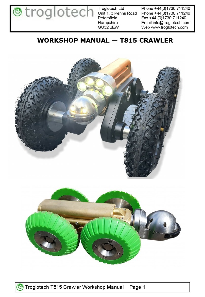
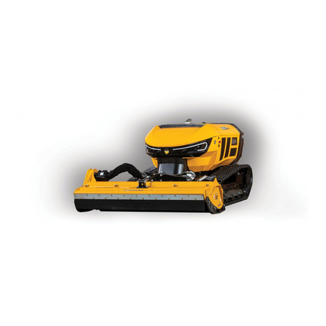
Troglotech T815 User manual

Troglotech T815 User Manual Page 1
OPERATING INSTRUCTIONS—T815 CRAWLER
Troglotech Ltd Phone +44(0)1730 711240
Unit 1, 3 Penns Road Phone +44(0)1730 711240
Petersfield Fax +44 (0)1730 711240
Hampshire Email info@troglotech.com
GU32 2EW Web www.troglotech.com
This manual is to be used with T804 Operating Instructions
VERSION 2—AUTO-DRUM + EXTENSIONS

Troglotech T815 Crawler User Manual Page 2
STANDARD CRAWLER - CONTENTS

Troglotech T815 User Manual Page 3
STANDARD CRAWLER - CONTENTS
8 ” Wheel set
AC Charger
T812 Camera Head
4 ” Wheel set 6 ” Wheel set
Pressure Pump
Tractor Body
Standard Battery x 2
DC Charger
Wheel Removal
Lifting Device
Carry Case
OR

Troglotech T815 Crawler User Manual Page 4
LARGE CRAWLER OPTION
2 x Wheel Extensions
Large Lighthead
4 x Large Pneumatic Wheels 4 x Small Pneumatic Wheels
Large Battery Pack

Troglotech T815 User Manual Page 5
THE CRAWLER

Troglotech T815 Crawler User Manual Page 6
THE MANUAL CABLE DRUM

Troglotech T815 User Manual Page 7
THE AUTO CABLE DRUM
The Auto-Drum Control Handle
The Control Handle is operated by pulling outwards (towards
the operator) and then moved upwards or downwards to select
operation. The handle can then be released when the
operation has been selected. This is best performed with the
left hand with the thumb braced against the legend plate, the
handle is designed with a strong spring so that the handle
cannot be inadvertently moved.
WARNING: The Drum can provide a lot of power and care should
be taken that the crawler cable is not snagged as this may dam-
age the cable. The Drum can realise a pull of around 12Kg so also
ensure that the drum cannot be pulled towards a culvert.

Troglotech T815 Crawler User Manual Page 8
THE AUTO CABLE DRUM
AUTO
This is the setting used for normal operation. The cable can be pulled from
the drum by hand or by the crawler. The drum is designed to provide a small
amount of tension in the cable so that if it is released the cable will return to the
drum. Auto works with or without the crawler so that cable can be pulled from the
drum without the crawler connected, the cable can then be connected to the
crawler when in place and the survey can start. There are no voltages or power in
the cable and it is safe to handle.
The cable drum will release cable when the crawler is moving forwards always
keeping a small amount of tension. It is the crawler that pulls the cable, the drum
uses its motor to keep in synchronisation with the crawler. The longer the forward
button is pressed the faster the crawler will move, press stop to halt the crawler
In reverse the Drum will pull the crawler back, in this mode the crawler
disconnects its wheel drives to allow it to be pulled. The longer the reverse
button is pressed the faster the crawler will move, press stop to halt the crawler.
In reverse the drum can provide a lot of pulling force so ensure the drum is
placed so that it cannot move or be pulled into a culvert.
In normal use (including transportation between sites) the drum can remain in
Auto.
TENSION
This mode allows the crawler to reverse under its own power and should be
used carefully ensuring the crawler does not run over the cable. This mode can
be used when the crawler needs to be manoeuvred, for instance if the crawler is
blocked by an obstruction when retrieving. This allows the crawler to power itself
over obstruction. In all other circumstances leave the drum in AUTO
DRUM LOCK and MANUAL REWIND
This position is used to lock the drum for transportation and for manually
rewinding the cable after the crawler has been removed or if the crawler battery is
exhausted. With the handle released in the DRUM LOCK position the motor
brakes are automatically applied. When the handle is lifted upwards from Drum
Lock cable will be rewound onto the drum. The further the handle is lifted away
from the DRUM LOCK position the faster the drum will rotate.
Manual Rewind can be used if the crawler has exhausted it’s power and
needs to be retrieved to replace the battery.

Troglotech T815 User Manual Page 9
FITTING EXTENSIONS AND LIGHTHEAD
FITTING WHEEL EXTENSIONS, LARGE BATTERY AND LIGHTHEAD
The Wheel Extensions, Large Battery and Lighthead are options to allow
surveying larger pipe sizes. The wheels are fitted to the extensions first:
Lay Wheel Extensions so that the wheel axles are upwards
Carefully align wheels and fit with locking bolts using the supplied
wheel tool. These do not have to be fitted with too much force and will
lock into place
Lay the crawler on its side so that three axles are upwards
Align the Extensions with the outer axles and rotate the wheels so
that the axles insert correctly
Fit the ratchet handle to the wheel tool and tighten the single central
bolt ensuring that the extensions are fully inserted onto the axles
Repeat for the other extension
Position the crawler upright
Remove any battery fitted to the crawler
Fit the large Lighthead using the two captive Allen bolts
Slide the Large Battery into position

Troglotech T815 Crawler User Manual Page 10
PREPARING SYSTEM FOR USE
Charging Batteries
Welcome to your T815 Tractor system. Please use these instructions together with
the T804 User Manual for full information on control of the Textwriter, DVR and
other features of the base unit.
Before use it is best practice to charge the two batteries supplied with the
Standard Tractor System. You can use either the mains charger (shown below) or
the DC charger. Connect the charger to the battery before connecting the mains or
DC supply. The charger connector is fitted by aligning the two screws to the two
apertures in the battery and turning clockwise—it will only fit in one orientation.
The LED on the charger shows the state of charge. RED means that the charger
is putting energy into the battery. When the battery is fully charged the LED will
change to GREEN.
If the LED does not show at all something is wrong—check the mains or DC
supply.

Troglotech T815 User Manual Page 11
CRAWLER BATTERY FITTING
Before fitting the charged battery ensure that the connector on the crawler and
battery are free from debris and dampness.
Slide the battery through from the rear and smartly snap the battery forwards to
fully mate—ensure that the battery cannot be pushed backwards to ensure it is
correctly fitted.
Fitting and releasing the crawler batteries
The battery packs slide from the rear onto the crawler body—to release a battery
from the crawler body first lift the release button and then push the battery back-
wards from the front as shown below. Slide the battery fully backwards until re-
leased from the crawler body.

Troglotech T815 Crawler User Manual Page 12
LOCKING WHEEL FITTINGS
Each wheel is fitted with a ratchet lock, this stops the
wheel bolts from working loose during operation. It is im-
portant that the wheel bolts are not forced anti-
clockwise or the ratchet may suffer damage.
To remove a wheel only the wheel-removal tool must be
used, do not use a standard wrench as this will damage
the ratchet ring.
To fit a wheel turn the
wheel bolt clockwise
until the ratchet can be
felt engaging, then apply
just a little force to fully
engage the wheel bolt.
To remove a wheel
firstly push the wheel
removal tool towards the
bolt until the ratchet ring
is depressed, then turn
anti-clockwise.
Do not force the wheel
bolt otherwise the
ratchet ring will be
damaged

Troglotech T815 User Manual Page 13
PRESSURISE THE CRAWLER
The crawler will lose pressure slowly during operation, this is normal as air
continually pressurises the main cable along the full 300M length. A sudden loss
of pressure indicates that the main cable has been damaged.
The pressure can be checked during operation by pressing the ‘D’ key
(DATA). This will show useful information as shown below:
If the pressure is
low a warning is
shown at the bottom
of the screen. If the
‘D’ key has not been
pressed a flashing ‘P’
will appear in its place
indicating a danger-
ously low pressure.
The crawler must be pressurised before use this pressure is monitored by the
control unit—if the pressure drops to low levels a flashing ‘P’ will appear on-
screen. Ensure both the pump and crawler rear connector is clear of debris
and dampness before pressurising.
Connect pump to rear connector of the crawler and pump to achieve a pressure of
2-3 BAR (30—45 psi).
Remove the pump from the rear connector. The crawler is now ready to be used.

Troglotech T815 Crawler User Manual Page 14
CONNECT THE CRAWLER TO THE DRUM
Once the crawler has been pressurised it can be connected to the cable drum.
There is no additional strain-relief required as the main cable is exceptionally
strong with Kevlar reinforcement.
The Cable Drum can be now be
switched ON at the GREEN
HUB BUTTON.
The front crawler lights will illu-
minate and the Pan & Tilt cam-
era will initialise until it is upright
and the lens is pointing for-
wards.
Ensure that Auto-Drum Con-
trol Handle is set to AUTO
ENSURE THAT THE CABLE TERMINATION AND CRAWLER CONNECTOR
IS CLEAN AND FREE FROM MOISTURE BEFORE CONNECTION

Troglotech T815 User Manual Page 15
LOWERING AND RAISING THE CRAWLER
Lifting device RELEASED Lifting device READY
Practice with the lowering device—it
is simple to lift the crawler but it takes
a bit of practice to get it right.
The pictures show the lowering claw—to
GRAB the crawler the claw must be in
the READY position. To get it into the
ready position dangle the claw and give
the rope a slight tug upwards, this will
close the claw ready for grabbing the
crawler—have a practice to get this op-
eration to be second nature.
Get the claw in the READY position and then care-
fully lower it over the battery flutes—if you do this
correctly the claw will grab onto the crawler.
If the claw releases tug the rope to get it back into
the READY position.
Once the claw is locked on the battery you can lift
the crawler safely.
As soon as the crawler is placed on the ground
the claw will release.
NEVER RAISE THE CRAWLER OVER ANY PERSONELL
IF THE LOWERING DEVICE FAILS THIS WILL CAUSE INJURY

Troglotech T815 Crawler User Manual Page 16
THE CRAWLER CONTROLS
The crawler speed and direction is controlled by these five buttons on the
keyboard. It is important to familiarise yourself with the operation of these!
The most important button is STOP, the button is raised to ensure that the
correct button is pressed. No matter what the crawler is doing the STOP but-
ton will stop it moving. Ensure the AUTO-DRUM is set to AUTO
To start the crawler moving forwards press the STOP button followed by the
FORWARDS button, the longer the forward button is pressed the faster it will
travel. You can reduce the speed by pressing the REVERSE button.
While the crawler is moving forwards you can press the LEFT or RIGHT buttons to
steer the crawler. When steering LEFT the crawler will reduce the power to the left
wheels, when turning RIGHT the crawler will reduce the power to the right wheels.
To get the crawler to turn on the spot, press STOP and then press LEFT or
RIGHT—the crawler will perform a multi-point turn on the spot. It uses this
routine to stop digging a hole and to reduce battery drain.
After all operations press the STOP button to halt any movement
FORWARD OPERATION

Troglotech T815 User Manual Page 17
REVERSING CAMERA
The forward and rear cameras and lighting is automatically controlled by the
crawler controls.
To enable the FRONT camera press FORWARD and then STOP
To enable the REAR camera and lights press REVERSE and then STOP
REVERSING
To operate in REVERSE press STOP and then REVERSE, the rear camera pic-
ture will be displayed and the rear lights will be switched ON. The crawler will start
moving slowly.
ENSURE THAT THE CRAWLER DOES NOT RUN OVER THE
CABLE BY MANUALLY REELING THE CABLE FROM THE
CABLE DRUM USING THE PULL-OUT HANDLE
IF AN AUTO-DRUM IS IN USE IT WILL BODILY PULL THE
CRAWLER IN REVERSE
In REVERSE the speed can be INCREASED by pressing the REVERSE key
In REVERSE the speed can be REDUCED by pressing the FORWARD key
In REVERSE the direction is controlled by the LEFT and RIGHT keys
Press STOP to halt the crawler
SONDE
The crawler has an in-built
32.768KHz sonde which is nor-
mally OFF to preserve power.
To switch the sonde ON press
the button shown below.
To switch the sonde OFF
press the button shown below.
NOTE: The OFF button is
shared with the ‘Centre Pan &
Tilt Camera’ control

Troglotech T815 Crawler User Manual Page 18
START RECORDING (OPTIONAL)
1) The Textwriter starts with the Rod
Counter, Time & Date and the Text
from Page 1 displayed
2) Use the keys shown here to hide
or display the Rod Counter, Time &
Date and the Text
4) Press RECORD (YES) to start a
recording
6) Press STOP (NO) to stop the re-
cording when finished.
3) After 15 seconds from switch-on
the ‘DVR READY’ message shows
5) Ensure the LED is flashing to show
a successful recording

Troglotech T815 User Manual Page 19
CAMERA CONTROLS
Standard Operation
When the T812 is fitted to Crawler System and the system switched ON, the Pan
& Tilt camera will perform a short calibration routine. During the calibration
routine the Tilt mechanism will turn and the picture will rotate on the T804 screen
as the internal picture sensor rotates. After a few seconds the main rotate
mechanism will adjust the camera to an upright position, the pan mechanism will
face forward and the picture will auto-upright. The camera is now ready for use.
When operating the camera using the keyboard, the camera can be set to view
straight-ahead and the Focus pre-set to 6”- infinity by pressing the ‘Centre’ button
on the keyboard as shown on the next page.
Always use this button after operating the camera pan, tilt and focus controls.

Troglotech T815 Crawler User Manual Page 20
PAN & TILT CAMERA CONTROLS
Standard Operation Continued
The picture to the right show the Pan & Tilt
camera head controls. Practice controlling
the camera head with the right-most four
controls for PAN and ROTATE until the
operation becomes second nature.
The left most button points the camera head
directly forwards with the picture fully upright
and the focus is set to the 6” to Infinity
setting. This button is very useful if
orientation has been lost and a starting
position is needed.
The picture is automatically kept upright
whilst panning and tilting, this is called
’Human Perspective View’ as it mimics how a
human would view a pipe.
The crawler automatically steers back to
the bottom of the pipe but it is important to
ensure the crawler is operating at the bottom
of the pipe rather than traversing the wall by
short presses on the LEFT of RIGHT buttons.
Borehole mode Pressing the button shown above puts the T812 camera into
Borehole mode. This switches OFF the Human Perspective View and allows the
operator to rotate the video picture using the ZOOM keys. Press CENTRE to enable
Human Perspective View
Maintaining your T812 camera
After completing a survey check the LED and lens windows for debris—remove any
debris with a soft cloth. Adjust the pan position so that the windows face the camera
body. This will protect the windows during transit to the next survey.
Do not use any solvents to clean T812 camera as they may damage the camera
seals and remove lubricating greases.
Other manuals for T815
1
This manual suits for next models
2
Table of contents
Other Troglotech Robotics manuals
