Trojan Technologies Aquafine TrojanUVLogic Series User manual

PLEASE KEEP FOR PERMANENT REFERENCE
Part Number 127 Rev E
7KLV PDQXDO FRYHUV WKH VHUYLFLQJ DQG JHQHUDO PDLQWHQDQFH UHTXLUHPHQWV IRU $TXDILQH 8OWUDYLROHW :DWHU
7UHDWPHQWHTXLSPHQW
DISINFECTION • TOC REDUCTION • OZONE DESTRUCTION • CHLORINE/CHLORAMINE DESTRUCTION
TrojanUVLogic Series
Installation & Operation Manual
It is imperative that those responsible for the installation
of this equipment, as well as operating personnel, read this
manual and carefully follow all instructions and guidelines.
EQUIPMENT OPERATORS AND INSTALLERS MUST COM-
PLY WITH OPERATIONAL SAFETY REQUIREMENTS.
A TROJAN TECHNOLOGIES COMPANY
READ THIS MANUAL

TrojanUVLogic
TM
Revision:E
LastUpdate:07AU21
PlaceSystemLabel
Here.
Ifnolabelhasbeen
placedhere,referto
thelabelonthe
UVEquipment
fordetails.
Forfurtherclarificationoflabelinformation,pleaserefertoChapter2,page23,“SystemVerification
LabelDefinitions”.
Recordsystemsetpointsindicatedbelow:
UVIntensitySetPoint
TheTrojanUVLogic
TM inthismanualmaybecoveredbyoneormoreofthe
followingUnitedStates(US)Patents:
US6,342,188
US6,659,431
US6,564,157
US6,635,613
OTHERPATENTSMAYBEPENDING.
COPYRIGHT©2008byAQUAFINECORPORATION
ALLRIGHTSRESERVED

Volume Table of Contents
Trojan ogicTM Operations and Maintenance
UVL
PREFACE III
GENERAL INFORMATION.....................................................................................................................III
IMPORTANT CONTACTS...................................................................................................................... IV
WARNINGS AND PRECAUTIONS......................................................................................................... V
GENERAL LOCKOUT PROCEDURES ................................................................................................. XI
Lockout and Tag Procedure...............................................................................................................xi
LIST OF ACRONYMS/GLOSSARY...................................................................................................... XII
TROJANUVLOGIC MAINTENANCE REQUIREMENTS
TM .................................................................. XIII
Maintenance Schedule .................................................................................................................... xiv
Maintenance Checklist.....................................................................................................................xvi
Alarm Log........................................................................................................................................ xvii
System Operating Parameters.........................................................................................................xix
Maintenance Log ..............................................................................................................................xx
Lamp Log Table...............................................................................................................................xxi
1 INTRODUCTION TO UV THEORY 1-1
1.1 OVERVIEW OF TROJANUVLOGICTM ............................................................................................1-1
1.2 WHAT IS ULTRAVIOLET LIGHT?..................................................................................................1-1
1.3 DISINFECTION VS. STERILIZATION.............................................................................................1-2
1.4 APPLICATIONS OF UV LIGHT ......................................................................................................1-2
1.5 FACTORS AFFECTING UV DISINFECTION..................................................................................1-2
UV Transmittance:...............................................................................................................................................1-3
Suspended Solids:..............................................................................................................................................1-3
Level of Total Dissolved Solids:..........................................................................................................................1-3
Total Hardness:...................................................................................................................................................1-4
Sleeve Cleanliness:.............................................................................................................................................1-4
Treatment Process:.............................................................................................................................................1-4
Flow Rate:............................................................................................................................................................1-4
2 SYSTEM OVERVIEW 2-1
2.1 SYSTEM COMPONENTS ...............................................................................................................2-1
UV Reactor (UVR)............................................................................................................................................2-1
Control Panel (CP)...........................................................................................................................................2-1
UV Sensor........................................................................................................................................................2-2
Wiping Systems ...............................................................................................................................................2-2
Automatic Mechanical Wiping System (AMWS)....................................................................................................................2-2
Manual Mechanical Wiping System (MMWS)........................................................................................................................2-3
Power Pack.................................................................................................................................................................................2-3
2.2 OPERATIONS OVERVIEW.............................................................................................................2-3

Volume Table of Contents
Trojan ogicTM Operations and Maintenance
UVL
Main Menu Screen........................................................................................................................ 7-18
Active Alarms Screen.................................................................................................................... 7-18
Alarms List Screen Series............................................................................................................. 7-18
Alarm History Screen.................................................................................................................... 7-18
Alarm History Details Screen........................................................................................................ 7-18
Digital Input-Output Screen Series ............................................................................................... 7-19
Operator Access Level Screens..................................................................................................................7-19
Technician Level Access Screens..............................................................................................................7-19
Analog Input-Output Screen Series.............................................................................................. 7-20
Operator Access Level Screens..................................................................................................................7-20
Technician Level Access Screens..............................................................................................................7-20
System Settings Screens.............................................................................................................. 7-21
Operator Access Level Screens..................................................................................................................7-21
Technician Level Access Screens..............................................................................................................7-22
Trend Screens .............................................................................................................................. 7-23
Wiper Screen (AMWS)(For systems with a Wiper)...................................................................... 7-24
Wiper Sequence Timer (AMWS) (For systems with a Wiper)................................................................7-24
Wiper Auto Power Off (For systems with a Wiper)..................................................................................7-24
Analog Menu Screen .................................................................................................................... 7-25
Reactor Hi Temp (Reactor High Temperature) Configure Screen (Optional)............................... 7-25
Login Screen................................................................................................................................. 7-26
7.4 SYSTEM STATUS ALARM LIST..................................................................................................7-27
7.5 ALARM OVERVIEW......................................................................................................................7-27
Minor Alarms................................................................................................................................. 7-27
Major Alarms................................................................................................................................. 7-28
Critical Alarms............................................................................................................................... 7-29
7.6 INPUT AND OUTPUT OVERVIEW ...............................................................................................7-30
Standard Inputs and Outputs........................................................................................................ 7-30
Optional Inputs and Outputs......................................................................................................... 7-30
Additional Inputs and Outputs....................................................................................................... 7-31
7.7 DIGITAL OUTPUT WIRING DIAGRAMS......................................................................................7-31
8 ALARMS AND TROUBLESHOOTING 8-1
8.1 ALARM INDICATORS.....................................................................................................................8-1
8.2 GENERAL TROUBLESHOOTING..................................................................................................8-9
9 INSTALLATION INSTRUCTIONS 9-1
9.1 OVERVIEW .....................................................................................................................................9-1
9.2 SHIPPING CONTENTS...................................................................................................................9-1
9.3 SET-UP............................................................................................................................................9-1

Volume Table of Contents
Trojan ogicTM Operations and Maintenance
UVL
UV Sensor...........................................................................................................................................................7-3
External Interfaces............................................................................................................................................7-3
SCADA Communication (Optional)...............................................................................................................7-3
Alarms.................................................................................................................................................................7-3
Auto Home Position Reset (if Wiper is provided).......................................................................................7-4
Reactor Proximity Switch Input (Rev Counter)...........................................................................................7-4
Alarm Output Relays........................................................................................................................................7-4
7.2 CONTROL PANEL (CP) HARDWARE...........................................................................................7-5
Description...................................................................................................................................... 7-5
Specifications ....................................................................................................................................................7-5
Maintenance.......................................................................................................................................................7-6
Power Pack..................................................................................................................................... 7-6
Description.........................................................................................................................................................7-6
Specifications ....................................................................................................................................................7-6
Electronic Ballasts........................................................................................................................... 7-6
Description.........................................................................................................................................................7-6
Maintenance.......................................................................................................................................................7-0
AM Model –Ballast Removal & Replacement ............................................................................7-0
AS & AL Model –Ballast Removal & Replacement....................................................................7-8
System Controller – The Control Board........................................................................................ 7-10
Description.......................................................................................................................................................7-10
Board Power supply requirements – AM Models....................................................................................7-10
P40 Board Power supply requirements –AS and AL Models................................................................7-10
Board Diagram.................................................................................................................................................7-11
RS232 Com Port......................................................................................................................7-13
Ballast Communication Ports...................................................................................................7-13
Lamp Status (Midflow Models Only) ........................................................................................7-13
Board Fuse...............................................................................................................................7-13
Keypad Connector ...................................................................................................................7-13
VFD Communication Port ........................................................................................................7-13
Battery Replacement......................................................................................................................................7-13
Input / Output Features..................................................................................................................................7-13
Programmable Output Relays..................................................................................................7-13
Digital Output Relays (if Wiper is provided) .............................................................................7-14
Digital Inputs ............................................................................................................................7-14
Analog Inputs...........................................................................................................................7-14
Analog Outputs ........................................................................................................................7-14
Operator Interface......................................................................................................................... 7-15
Operation..........................................................................................................................................................7-15
Specifications ..................................................................................................................................................7-15
Maintenance.....................................................................................................................................................7-16
7.3 CONTROL PANEL (CP) SOFTWARE..........................................................................................7-16
Boot Menu Screen........................................................................................................................ 7-16
Main Display Screen..................................................................................................................... 7-16
UV Sensor..................................................................................................................................... 7-16
Reactor Temp Option (4 – 20 Analog Required): ......................................................................... 7-17

Volume Table of Contents
Trojan ogicTM Operations and Maintenance
UVL
5 MECHANICAL WIPING SYSTEM (OPTIONAL) 5-1
5.1 INTRODUCTION .............................................................................................................................5-1
Description...................................................................................................................................... 5-1
5.2 MANUAL MECHANICAL WIPING SYSTEM (MMWS) (OPTIONAL).............................................5-1
Description...................................................................................................................................... 5-1
Maintenance ................................................................................................................................... 5-1
Manual Wiper Assembly Removal....................................................................................................................5-1
Push Retainer Replacement..............................................................................................................................5-2
Sleeve Wiper Replacement (MMWS)...............................................................................................................5-3
5.3 AUTOMATIC MECHANICAL WIPING SYSTEM (AMWS) (OPTIONAL) ....................................5-5
Description...................................................................................................................................... 5-5
Wiping System Drive...........................................................................................................................................5-5
Wiping System Operation...................................................................................................................................5-5
Specifications.................................................................................................................................. 5-5
Maintenance ................................................................................................................................... 5-5
Gear Motor Removal...........................................................................................................................................5-5
Stop Plate Bushing Replacement......................................................................................................................5-7
Drive Screw Roller Bearing, O-ring & Seal Replacement...............................................................................5-8
Sleeve Wiper Replacement (AMWS)................................................................................................................5-9
Drive Nut Removal /Replacement..................................................................................................................5-12
6UVSENSOR 6-1
6.1 INTRODUCTION .............................................................................................................................6-1
Description...................................................................................................................................... 6-1
Specifications.................................................................................................................................. 6-1
Maintenance ................................................................................................................................... 6-1
UV Sensor Removal and Cleaning................................................................................................................6-1
UV Sensor Replacement .................................................................................................................................6-2
7CONTROLPANEL(CP) 7-1
7.1 OPERATIONAL DETAILS ..............................................................................................................7-1
Controls Philosophy........................................................................................................................ 7-1
Control System Overview ...............................................................................................................................7-1
UV Reactor Control...........................................................................................................................................7-1
Normal Operation Start-up..............................................................................................................................7-1
Normal Operation..............................................................................................................................................7-1
Shutdown............................................................................................................................................................7-2
Lamp Control and Monitoring........................................................................................................................7-2
Wiping System (Optional) ...............................................................................................................................7-2

Volume Table of Contents
Trojan ogicTM Operations and Maintenance
UVL
Control System Overview ............................................................................................................... 2-3
2.3 SYSTEM VERIFICATION LABEL DEFINITIONS...........................................................................2-4
3 START UPAND SHUT DOWN PROCEDURES 3-1
3.1 START UP UV SYSTEM.................................................................................................................3-1
3.2 SHUT DOWN UV SYSTEM.............................................................................................................3-1
4UVREACTOR(UVR) 4-1
4.1 INTRODUCTION .............................................................................................................................4-1
Description...................................................................................................................................... 4-1
Specifications.................................................................................................................................. 4-3
Maintenance ................................................................................................................................... 4-3
4.2 END CAPS ......................................................................................................................................4-3
Description...................................................................................................................................... 4-3
Specifications.................................................................................................................................. 4-3
Maintenance ................................................................................................................................... 4-3
End Cap Removal & Installation....................................................................................................................4-3
For Bolt-On Flange Style End Plates (20+cm Diameter Models)...............................................4-3
For Sanitary Clamp Style (Up to and including 20cm diameter chambers) ...............................4-4
4.3 UV LAMP ASSEMBLY....................................................................................................................4-4
Description...................................................................................................................................... 4-4
Specifications.................................................................................................................................. 4-4
Maintenance ................................................................................................................................... 4-4
Maintenance ................................................................................................................................... 4-5
Lamp Inspection/Replacement......................................................................................................................4-5
Elapsed Time Reset..........................................................................................................................................4-7
Lamp Number Configuration..........................................................................................................................4-7
4.4 QUARTZ SLEEVES ........................................................................................................................4-7
Description...................................................................................................................................... 4-7
Specifications.................................................................................................................................. 4-7
Maintenance ................................................................................................................................... 4-8
Sleeve Replacement.........................................................................................................................................4-8
Sleeve Cleaning...............................................................................................................................................4-11
Sleeve Cleaning Solutions.......................................................................................................4-11
Sleeve Cleaning Procedure .....................................................................................................4-11
Sleeve Holder / Wiper Assembly Removal................................................................................................4-11
Sleeve Bushing Replacement......................................................................................................................4-13
4.5 TEMPERATURE SWITCH ............................................................................................................4-15
Description.................................................................................................................................... 4-15
Specifications................................................................................................................................ 4-15

Volume Table of Contents
Trojan ogicTM Operations and Maintenance
UVL
9.4 AUTOMATIC MECHANICAL WIPING SYSTEM (AMWS) INSTALLATION..................................9-4
9.5 SYSTEM START-UP.......................................................................................................................9-4
Appendices................................................................................................. ..
APPENDIX A........................................................................................................................ WARRANTY
........................................................................................................................ Certificate of Equipment Warranty
APPENDIX B.............................................................................................REPLACEMENT PARTS LIST
APPENDIX C............................................................................................................................LAYOUT DRAWINGS
.................................... LG0001D01 - STD., UVLOGIC SHORT LAMP 40 SERIES (AMWS AND NO WIPING)
.......................................LG0004D01 - STD., UVLOGIC LONG LAMP 50 SERIES (AMWS AND NO WIPING)
............................................................LG0005D01 - STD., UVLOGIC LONG LAMP 30 SERIES (NO WIPING)
....................................................................LG0006D01 - STD., UVLOGIC LONG LAMP 30 SERIES (MMWS)
....................................................................LG0007D01 - STD., UVLOGIC LONG LAMP 30 SERIES (AMWS)
..............................................LG0008D01 - STD., UVLOGIC SHORT/LONG LAMP 20 SERIES (NO WIPING)
.....................................LG0009D01 - STD., UVLOGIC SHORT/LONG LAMP 20 SERIES (NO WIPING) ANSI
......................................................LG0010D01 - STD., UVLOGIC SHORT/LONG LAMP 20 SERIES (MMWS)
........................... LG0011D01 - STD., UVLOGIC SHORT/LONG LAMP 20 SERIES (MMWS) ANSI
..................................................... LG0012D01 - STD., UVLOGIC SHORT/LONG LAMP 20 SERIES, (AMWS)
............................................. LG0013D01 - STD., UVLOGIC SHORT/LONG LAMP 20 SERIES (AMWS) ANSI
.................................................................... LG0014D01 - STD., UVLOGIC MIDFLOW SERIES, (NO WIPING)
.......................................................... LG0015D01 - STD., UVLOGIC MIDFLOW SERIES, (NO WIPING) ANSI
........................................................................... LG0016D01 - STD., UVLOGIC MIDFLOW SERIES, (MMWS)
...................................................................LG0017D01 - STD., UVLOGIC MIDFLOW SERIES, (MMWS)ANSI
APPENDIX D..................................................................................................ELECTRICAL DRAWINGS
..............................................LG0002D01 – STD., UVLOGIC SINGLE LINE DIAGRAM – MIDFLOW MODELS
..........................LG0003D01 – STD., UVLOGIC SINGLE LINE DIAGRAM – SHORT / LONG LAMP MODELS
.............................................................................LG0018D01 – STD., UVLOGIC INTERCONNECT DIAGRAM
APPENDIX E...................................................................................SCADA COUMMICATION MODULE
E.1 P40 MODBUS ACTIONS AT POWER UP...................................................................................................V
E.2 MODBUS COMMANDS...............................................................................................................................VI
E.3 LOGIC/SWIFTSC CCB RECEIVE PROTOCOL (FROM PLANT PLC)....................................................... IX
E.4 LOGIC/SWIFTSC CCB TRANSMIT PROTOCOL (FROM P40 TO PLC)....................................................X
E.5 REVISION HISTORY................................................................................................................................XXII

PREFACE
TrojanUVLogic
TM Operations&Maintenance
i
Preface ....................................................................................................iii
GENERALINFORMATION ................................................................................................................................ III
IMPORTANTCONTACTS..................................................................................................................................IV
WARNINGSANDPRECAUTIONS......................................................................................................................V
GENERALLOCKOUTPROCEDURES ..............................................................................................................XI
LockoutandTagProcedure...........................................................................................................................xi
LISTOFACRONYMS/GLOSSARY...................................................................................................................XII
TROJANUVLOGIC
TM MAINTENANCEREQUIREMENTS................................................................................XIII
MaintenanceSchedule ................................................................................................................................xiv
MaintenanceChecklist.................................................................................................................................xvi
AlarmLog.................................................................................................................................................. xviii
SystemOperatingParameters.....................................................................................................................xix
MaintenanceLog..........................................................................................................................................xx
LampLogTable ..........................................................................................................................................xxi

PREFACE
TrojanUVLogic
TM Operations&Maintenance
ii

PREFACE
TrojanUVLogic
TM Operations&Maintenance
iii
PREFACE
GeneralInformation
Congratulationsonyourpurchaseofthe
TrojanUVLogic
TM
ThisOperationsandMaintenance(O&M)
Manualprovidesinstructionsonhowtooperate
thesystemandcarryoutroutinemaintenance.
Theobjectiveofthismanualistoprovide
simple,clearandcompleteinstructions.Itis
backedbyAquafineCorporationscommitment
tooffersuperiorcustomersupport.Everyeffort
hasbeentakentoensuretheaccuracyand
completenessofinformationinthismanual.
Ifyoudonotunderstandanyofthe
informationorprocedureexplanationsin
thismanual,callyourAquafineService
Providerforassistance.
Donotundertakeoperation,repairsor
servicingofequipmentunlessyouarefamiliar
withtheoperationandservicingoftechnical
equipmentandaretrainedinelectricaland
mechanicalsafety.
Ifyourleveloftraining,skillorcomprehension
ofthemanual’sinstructionscouldpossibly
resultininjuryordamagetotheequipment,
havetheworkdonebyaqualifiedoperatorora
Aquafinerepresentative.Yourcommonsense
andgoodjudgmentarecrucialtothesafeand
successfuloperationandmaintenanceofthe
TrojanUVLogic™.
1. ReadtheWarningsandPrecautions and
GeneralLockoutProcedure inthissection
beforeoperatingorperformingany
maintenanceonthisequipment.
2. Readprocedures thoroughlybeforestarting.
3. Reviewallwarningsandcautionsthat
accompanyanyprocedureandreviewthe
WarningsandPrecautions sectioneachtime
youpreparetoperformmaintenanceonthe
TrojanUVLogic
TM
Threetypesofnoticesareusedinthismanual.
WARNING
CONTAINSINFORMATIONTHATIF
NOTHEEDED,MAYRESULTIN
INJURYTOPERSONNELOR
EQUIPMENTDAMAGE.
CAUTION
TELLSREADERSWHENCAREIS
NEEDEDTOPREVENTEQUIPMENT
DAMAGE.
Note:PROVIDESCOMMENTSWHICHCLARIFY
INFORMATION.
ThissectionoftheO&MManualcontains
ImportantContacts,WarningsandPrecautions,
GeneralLockoutProcedures,andaListof
AcronymsandGlossaryofTerms.
Chapter1providesanintroductionintothe
theoryofultravioletlightdisinfection.
Chapter2 isanoverviewofthe
TrojanUVLogic™ComponentsandOperation
anddescribesregularMaintenance
Procedures.
Chapter3 providesinstructionsforthestartup
andshutdownoftheTrojanUVLogic
TM
Chapters4 7 providesdetailsforthe
operation,maintenanceandspecificationsfor
themajorcomponentsoftheTrojanUVLogic
TM
includingtheUVReactor(UVR),Lampsand
Sleeves,UVSensor(s),ControlPanel,and
optionalManualorAutomaticMechanical
WipingSystems.
Chapter8 providesinformationonAlarmsand
Troubleshooting.
Chapter9 – providesInstallationInstructionsfor
theTrojanUVLogic
TM

PREFACE
TrojanUVLogic
TM Operations&Maintenance
iv
Appendicesincludeavarietyofmaterialsuch
asElectricalDrawings,LayoutDrawingsand
theEquipmentWarranty.
ImportantContacts
AQUAFINECORPORATION
HeadOffice(Canada)
29010AvenuePaine
Valencia,CA91355
TollFree:18004233015
(outsideCA,withinUSA&Canadaonly)
Phone:6612574770
Fax:6612572489
Internet:www.aquafineuv.con
Europe†
AquafineGmbH
Ramskamp7785
D25337Elmshorn
Germany
Phone:+49(4121)5780613
Fax:+49(4121)5780630
†ForprojectsinContinentalEurope
LocalRepresentative

PREFACE
TrojanUVLogic
TM Operations&Maintenance
v
WarningsandPrecautions
Pleasereadwarningsandprecautionsbeforeproceedingwithoperation,maintenanceorrepairofthe
equipment.Alwaysfollowlocalsafetycodesandensuretoolsandpersonalprotectiveequipmentarein
goodconditionandproperlyfittedandtested.
WARNING
WearUVResistantFaceShield!
UNPROTECTEDEXPOSURETOULTRAVIOLETLIGHTCANCAUSESEVERE BURNSTOTHEEYESAND
SKIN. FACESHIELDSHOULDBEWORNASTHEPRIMARYPROTECTIONAGAINSTSUCHEXPOSURE.
NEVERLOOKDIRECTLYATTHEENERGIZEDLAMPSUNLESSYOUAREWEARINGULTRAVIOLET
RESISTANTFACESHIELDORGLASSES(FORSHORTTERMEXPOSURE)
EyeProtectionMustbeWorn!
ASADDEDPROTECTION,ORASAMINIMUMPROTECTIONFORSHORTTERMEXPOSURES,TIGHT
FITTINGGLASSESWITHSIDESHIELDSPROTECTIONWHERESUCHSHIELDSARECONTIGUOUSMUST
BEWORNATALLTIMESWHENTHEREISAPOTENTIALEXPOSURETOULTRAVIOLETLIGHT. GLASSES
SUCHASWRAPAROUNDSTYLEAREMOSTEFFECTIVE.
WearProtectiveGloves!
ALWAYSWEARPROTECTIVEGLOVESWHENWORKINGONEQUIPMENT.
WearSafetyBoots!
ALWAYSWEARPROTECTIVEFOOTWEARWHENWORKINGONEQUIPMENT.
WearEarProtection!
THETROJANUVLOGIC™DOESNOTPRODUCEAHARMFULLEVELOFNOISE,BUTUSERSARE
CAUTIONEDTHATTHEYSHOULDWEARHEARINGPROTECTIONASAPPROPRIATETOPROTECT
AGAINSTOTHERNOISETHATMAYBEPRESENTATAWASTEWATERORWATERTREATMENTPLANT.

PREFACE
TrojanUVLogic
TM Operations&Maintenance
vi
WARNING
ElectricalHazard!
BECAUSEOFTHEPOTENTIALHAZARDFROMTHISPOWERSOURCE,ITISPRUDENTTOUSELOCK
OUTPROCEDURESANDTAGALLSOURCESOFPOWERBEFOREPERFORMINGANYMAINTENANCE,
CLEANINGORREPAIRSONANYPIECEOFEQUIPMENT. THEPOWERSOURCESMAYINCLUDE
ELECTRICALORSTOREDENERGY. REFERTOTHEGENERALLOCKOUTANDTAGPROCEDURESIN
THISMANUAL.
WearHardHat!
WEARANAPPROVEDHARDHATANDOTHERPERSONALPROTECTIVEEQUIPMENTTHATISREQUIRED
ACCORDINGTOCONSTRUCTIONSITE,WASTEWATERORWATERTREATMENTPLANTSAFETY
REGULATIONS.
TripHazard!
STAYALERTANDBEAWAREOFPOTENTIALTRIPHAZARDSBEFOREWORKINGONEQUIPMENT.
HotSurface!
ALLOWELECTRONICBALLASTANDLAMPSTOCOOLBEFOREHANDLING.
ULTRAVIOLETLAMPSBECOMEHOTDURINGOPERATION. HOTLAMPSCANCAUSESERIOUS BURNS.
ALLOWTHELAMPSTOCOOLBEFORESERVICING.
3~THREEPHASEALTERNATINGCURRENT!
~SINGLEPHASEALTERNATINGCURRENT!

PREFACE
TrojanUVLogic
TM Operations&Maintenance
vii
WARNING
|ON(SUPPLY)
OFF(SUPPLY)
PROTECTIVEEARTHTERMINAL!
PINCHHAZARD!
CONSULTYOURTECHNICALMANUALBEFORESERVICING!

PREFACE
TrojanUVLogic
TM Operations&Maintenance
viii
CAUTION
THELAMPSINTHISSYSTEMEMITULTRAVIOLETLIGHT. EXPOSURETOULTRAVIOLETLIGHTCANCAUSE
SERIOUSBURNSTOUNPROTECTEDEYESANDSKIN. NEVERVIEWULTRAVIOLETLIGHTDIRECTLYWITH
THENAKEDEYE. ALWAYSUSETHEPROPERPROTECTIVEEYEWEARORAUVRATEDVIEWPORT.
ALWAYSWEARPROTECTIVECLOTHINGWHENEXPOSEDTOULTRAVIOLETLIGHT. ENSUREALLLAMPS
AREPROPERLYSECUREDWITHINTHEUVRCHAMBERBEFORETURNINGTHESYSTEMON. TURNTHE
SYSTEMOFFBEFORESERVICING.
TOPREVENTELECTRICALSHOCK,TURNTHESYSTEMOFFBEFOREREMOVINGANYOFTHECOVERSON
THEUVRCHAMBEROROPENINGTHECONTROLPANEL.
TOAVOIDPERSONALINJURY,TURNOFFPOWERBEFOREREMOVINGREACTORENDCAP.
ULTRAVIOLETLAMPS,ANDTHESLEEVESTHEYAREHOUSEDIN,ARECONSTRUCTEDOFQUARTZ
TUBING. QUARTZTUBINGISVERYFRAGILEANDEASILYFRACTURED. DONOTSTRIKE,BENDORAPPLY
PRESSURETOTHISMATERIALORITWILLBREAK. BROKENLAMPSORSLEEVESCANCAUSESERIOUS
CUTS.
DISCARDLAMPSANDSLEEVESACCORDINGTOTHEREQUIREMENTSOFYOURJURISDICTION.
ACIDSUSEDFORCLEANINGTHESLEEVESMAYCAUSEBURNS. WEARPROTECTIVECLOTHINGAND
PROTECTIVEEYEWEARWHENUSINGTHESEMATERIALS. AFTERCLEANING,RINSETHESYSTEM
COMPONENTSTHOROUGHLYWITHDISTILLEDWATER. ALWAYSFOLLOWTHESAFETYPRECAUTIONS
RECOMMENDEDBYTHEMANUFACTUREROFTHECLEANINGSOLUTION.
ACIDSUSEDTOCLEANTHESENSORCANCAUSEBURNS. WEARPROTECTIVECLOTHINGANDEYEWEAR
WHENHANDLINGTHESEMATERIALS. AFTERCLEANING,RINSETHESYSTEMCOMPONENTS
THOROUGHLYWITHDISTILLEDWATER. ALWAYSFOLLOWTHESAFETYPRECAUTIONSRECOMMENDEDBY
THEMANUFACTUREROFTHECLEANINGSOLUTION.
THISSYSTEMUSESULTRAVIOLETLIGHTTOREDUCETHECONCENTRATIONOFPATHOGENSTOANON
INFECTIOUSLEVEL. NONOBSERVANCEOFTHEMAINTENANCEINSTRUCTIONSORTHEALARM
MESSAGESWILLDIMINISHTHEEFFECTIVENESSOFTHISSYSTEM. REQUIREDDISINFECTION
EFFECTIVENESSISNOLONGERGUARANTEEDANDTHATTHEREQUIREMENTSOFTHEWATERSUPPLY
REGULATIONSARENOLONGERBEINGMET. AHEALTHRISKEXISTS.
THISSYSTEMISDESIGNEDTOWORKOPTIMALLYUNDERTHEREQUIREMENTSDESCRIBEDBYTHE
CUSTOMER. ANYMODIFICATIONTOTHESEFACTORSMAYREDUCETHEEFFECTIVENESSOFTHE
DISINFECTIONOFTHESYSTEM. THEFACTORSTHATAFFECTOPERATIONMAYBEFOUNDINTHE
INTRODUCTIONTOUV THEORY. SEECHAPTER1.
REMOVETHEENDCAPCOMPLETELY. DONOTALLOWTHEENDCAPTOHANGONTHEWIPERHANDLE
WHILECONDUCTINGWORK.
THESLEEVESMAYBELEFTINTHEWIPERASSEMBLYWHENTHESTOPPLATEISREMOVED;HOWEVER,
IFTHESLEEVESARENOTREMOVED,YOUMUSTENSURETHEYAREPROPERLYSUPPORTEDWHENTHE
STOPPLATEISNOTTHERETOAVOIDDAMAGE.
ITISESSENTIALTHATTHECOMPONENTSOFTHESTOPPLATEASSEMBLYBEPROPERLYINSTALLEDON
TOTHEENDOFTHEDRIVESCREWFORCONSISTENTWIPEROPERATION.
FAILURETODOSOMAYRESULTINIMPROPERWIPEROPERATION.
LONGLAMPSYSTEMS(ALMODELS)HAVETWOSEPARATEWIPERASSEMBLIESMOUNTEDONTOTHE
DRIVESCREW. MAINTAINTHEDISTANCEOF28” CENTERTOCENTERBETWEENTHETWOWIPER

PREFACE
TrojanUVLogic
TM Operations&Maintenance
ix
CAUTION
ASSEMBLIES. THISISTOMAINTAINFULLWIPINGCOVERAGEOFTHESLEEVESANDPREVENTJAMMING
OFTHEWIPERASSEMBLYONTHEOUTLETENDOFTHECHAMBER.
IFYOUHEARORSUSPECTSLEEVEBREAKAGE,DONOTWIPEBYRESETTINGTHEPOWER. YOUWILL
BREAKMORESLEEVESORLAMPS.
INSTALLATIONANDMAINTENANCETOBEPERFORMEDBYQUALIFIEDPERSONNELONLY.
THISSYSTEMISDESIGNEDONLYFORINDOORUSE.
THISSYSTEMCANDISINFECTONLYWATER.
NEVEROPERATETHEUNITWHILEEMPTYORWITHOUTFLOWFORANEXTENDEDPERIOD.
OPERATETHESYSTEMONLYIFTHECHAMBERISCOMPLETELYFILLEDWITHFLOWINGWATER.
INTERMITTENTOPERATIONOFTHESYSTEMREQUIRESTHATAMINIMUMAMOUNTOFWATERFLOWS
THROUGHTHESYSTEMINORDERTOCOOLTHELAMPS.
CONNECTTHISSYSTEMONLYTOACPOWERTHATCONFORMSTOTHEINFORMATIONINTHERATING
PLATEASREGARDSVOLTAGEANDVOLTAGESPECIFICATION.
IFYOURSYSTEMRUNSWITHPULSECOMPRESSION,ABUFFERTANKOROTHERREMEDIALMEASURE
MUSTBEPROVIDED.
THEULTRAVIOLETEMISSIONOFTHESELAMPSDECREASESOVERTIME. THEUV LAMPSINTHISSYSTEM
MUSTBEREPLACEDEVERY9000HOURSOFOPERATIONINORDERTOENSUREPROPEROPERATION,
SEECHAPTER4.
REGULARTESTINGOFSYSTEMPERFORMANCEUSINGSTANDARDIZEDMETHODS(E.G.,WATERSUPPLY
REGULATIONSOFVARIOUSCOUNTRIES)ISRECOMMENDED. WHENINSTALLINGTHE
TROJANUVLOGIC
TMSYSTEM,ALLOWENOUGHROOMFORSAMPLINGPOINTS.
ALLREPAIRSARETOBEDONEBYAQUAFINECORPORATION’SSERVICEORBYQUALIFIEDSPECIALISTS.
DEPRESSURIZE& DRAINTHEUVR.
PRESSUREMUSTBERELIEVEDFROMTHESYSTEMPRIORTOANYMAINTENANCE,TOPREVENTDAMAGE
TOTHEEQUIPMENTORPERSONALINJURY.
TOAVOIDPERSONALINJURY,TURNOFFPOWERBEFOREREMOVINGUVR ENDCAP.
FORCORRECTINSTALLATION,FOLLOWTHEINSTALLATIONINSTRUCTIONSINCHAPTER9. REFERTO
THEAPPROPRIATEELECTRICALDIAGRAMINAPPENDIXD,WHICHSHOWSHOWTOSETUPTHEPROPER
SYSTEMCONNECTIONSBETWEENTHECONTROLPANELANDTHEREACTORCHAMBER.

PREFACE
TrojanUVLogic
TM Operations&Maintenance
x
CAUTION
ATTENTION
OBSERVE PRECAUTIUONS
FOR HANDLING
ELECTROSTATIC
SENSITIVE
DEVICES

PREFACE
TrojanUVLogic
TM Operations&Maintenance
xi
GeneralLockoutProcedures
Thefollowinglockoutprocedureistheminimum
requirement.Additionalprecautionsshouldbe
takendependingonsitespecificprotocols.
Alwayscheckwiththeplantmanagerand
seniorelectricianforadditionalprecautions.
WARNING
EYEPROTECTION! WEARUV
RESISTANTFACESHIELDWHEN
LOOKINGATLAMPSORREACTION
CHAMBER.
WARNING
HANDPROTECTION! WEARPROPER
GLOVESANDCLOTHINGWHEN
SERVICINGEQUIPMENT.
WARNING
FOOTPROTECTION! WEARPROPER
FOOTPROTECTIONBEFORE
ENTERINGAWATERTREATMENT
PLANT.
LockoutandTagProcedure
1. Locateandidentifyelectricalsupplyto
equipment.Identifyspecificbreakersor
disconnectsthatservice AquafineCorporation
equipment.Ifyouareunsure,contacttheplant
electricianormaintenancepersonneltolocate
thecorrectelectricalsupply.
WARNING
BEAWARETHATTHEPANELMAYBE
FEDFROMMULTIPLESOURCES!
2. WhilestandingtothesideoftheElectrical
Panel,useyourclosestarmtomovethe
RotaryDisconnectSwitchtotheOFFposition.
3. AttachyourLockandSafetyTagtotheRotary
DisconnectSwitch.Includeyourname,date
andtime,andtheworktobeperformedonthe
tag.
4. ReturntotheControlPanel(CP)andverify
correctpowersourcehasbeenlockedout.
WARNING
THEEQUIPMENTMAYHAVE
STOREDENERGY! ENSURETHAT
ALLPARTSHAVESTOPPED
MOVINGANDANYSTORED
CAPACITANCEHASBEEN
EFFECTIVELYDRAINED.
5. Proceedtotheworkareaandvisuallycheckto
ensurethattheequipmentisOFF.
6. DoublecheckwithaMultimeteratthe
equipmentServiceEntrancetoensurethatthe
systemhasbeendeenergized.
7. Wait fiveminutes oncesystemisturned
OFF,toallowforCapacitiveDischarge.
8. Itisnowsafetoworkonthesystem.
9. Completeallrequiredmaintenance.
AfterServiceWorkIsComplete
10.EnsureCPdoorisclosed.
11.EnsurealloftheequipmentisintheOFF
position.
12.Clearanytoolsordebrisfromworkarea.
13.RemoveallLockoutDevicesandTags.
14.WhilestandingtothesideoftheElectrical
Panel,useyourclosestarmtomovethe
RotaryDisconnectSwitchtotheONposition.
15.Notifytheplantmanagerorsiteelectricianthat
workiscompleteandthatthesystemhas
beenrestarted.

PREFACE
TrojanUVLogic
TM Operations&Maintenance
xii
ListofAcronyms/Glossary
Thisglossarydefinesalistofacronymsthatwill
befoundthroughoutthismanual.
o
C–DegreesCelsius
AC–AlternatingCurrent
_LLongLampLogicModel
AMWSAutomaticMechanicalWipingSystemis
anoptionalcomponentthatprovidesautomated
wipingoftheLampSleevesduringnormal
operation.
ANSI–AmericanNationalStandardsInstitute
_SShortLampLogicModel
BarBarometricPressure
BSP–BritishStandardPipe
CCB–CommunicationControlBoard
cmCentimeter
CPControlPanel
DC–DirectCurrent
DINDeutscheIndustrieNorm(German
EquivalentofANSI)
DNADeoxyribonucleicAcid
EOLEndofLife
GNDGround
GPMUSGallonsperMinute
Hp–Horsepower
Hrs–Hours
in
.
lb–Inchpound
Lb
.
ft–PoundFoot
L/s–Literspersecond
LEDLightEmittingDiode
mA–Milliamps
MAXMaximum
MGDMillionsofGallonsperDay
mg/l–Milligramsperliter
MIN–Minimum
mJ/cm
2Millijoulespersquarecentimeter
MLDMillionsofLitersperDay
mmMillimeters
MMWSManualMechanicalWipingSystemis
anoptionalcomponentthatprovidesthe
operatortheabilitytowipetheLampSleeves
duringnormaloperation.
MPaMegapascals
mW/cm
2Milliwattspersquarecentimeter
N
.
m–Newtonmeter
nm–Nanometers
NPT–NationalPipeThread
O&MOperationsandMaintenance
OH–HydroxylFreeRadicals
phPhase
ppm–PartsperMillion
psi–PoundsperSquareInch
sec–Second
SST–StainlessSteel
TOC–TotalOrganicCarbon
UVUltraviolet
UVRUVReactor
VAC–VoltageAlternatingCurrent
VDC–VoltageDirectCurrent
VFD–VacuumFluorescentDisplay
w–Wire
W/m
2–Wattspermetersquared
Table of contents
Other Trojan Technologies Water Filtration System manuals
Trojan Technologies
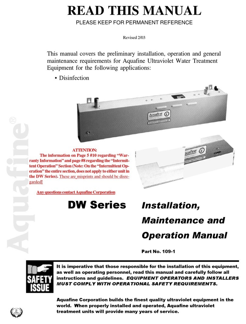
Trojan Technologies Aquafine DW Series User manual
Trojan Technologies
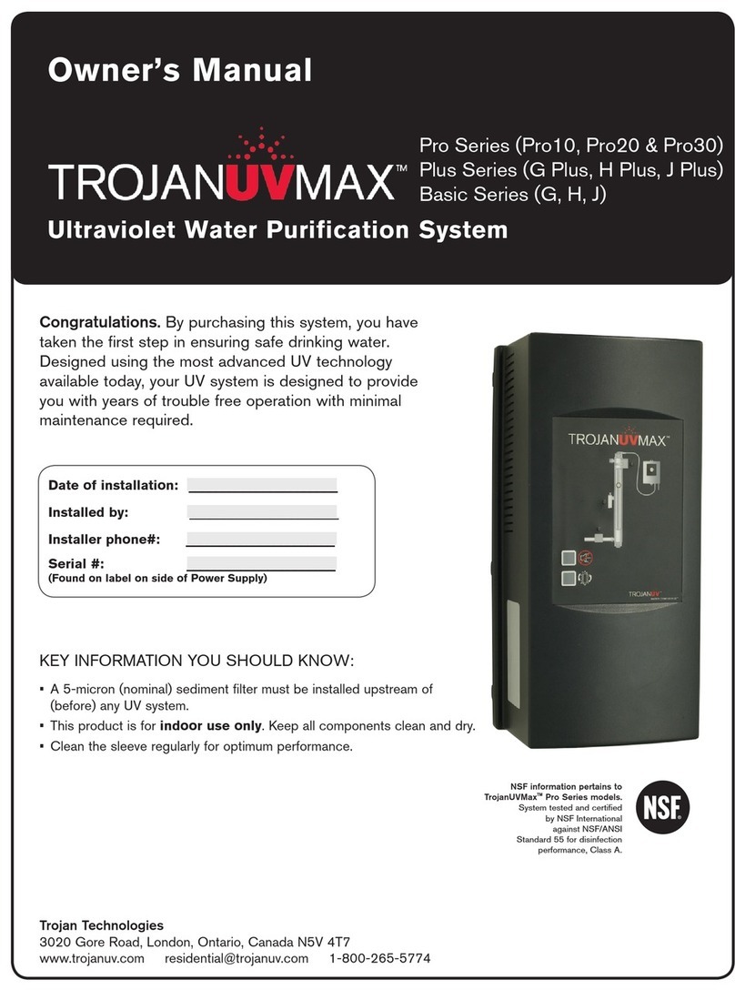
Trojan Technologies TrojanUVMax Pro10 User manual
Trojan Technologies
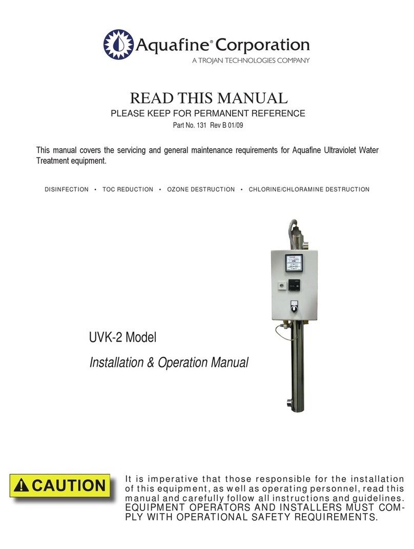
Trojan Technologies Aquafine UVK-2 User manual

Trojan Technologies
Trojan Technologies Trojan UV Max User manual
Trojan Technologies
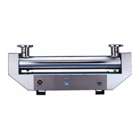
Trojan Technologies Aquafine CSL Series User manual
Popular Water Filtration System manuals by other brands
Dontek
Dontek PWP2 Ioniser instruction manual
Barco
Barco F40 installation manual

Petsafe
Petsafe DRINKWELL hy-drate PFD17-12901 quick start guide

Richdon Koi
Richdon Koi UltraSieve MIDI instruction manual
MEDENUS
MEDENUS DF 100 Operating and maintenance instructions

Keating Of Chicago
Keating Of Chicago Safe and Easy Filter owner's guide
