Trojan Flooded User manual

USER’S GUIDE

Congratulations
on your purchase from Trojan Battery Company, the manufacturer of the
world’s most trusted deep-cycle batteries. The battery you purchased was
engineered by Trojan to deliver superior power, performance, durability
and reliability for use in a broad range of demanding applications. From the
T2 Technology™ in our ooded batteries to the C-Max Technology™ in the
Reliant™ AGM line, our goal is to provide clean and reliable energy storage
solutions that enhance the way people live and work around the world.

This User’s Guide
was created by Trojan’s application engineers and contains vital information
regarding proper care and maintenance of your new battery. Please read through
this User’s Guide carefully and completely before using your battery. It will help
you achieve optimum performance and long life from your new investment.
800-423-6569 Ext. 3045 / +1-562-236-3045
TECHNICAL SUPPORT

Contents
01 Safety . . . . . . . . . . . . . . . . . . 5
02 Equipment Needed. . . . . . . . . . . . 5
03 Battery Installation . . . . . . . . . . . 6
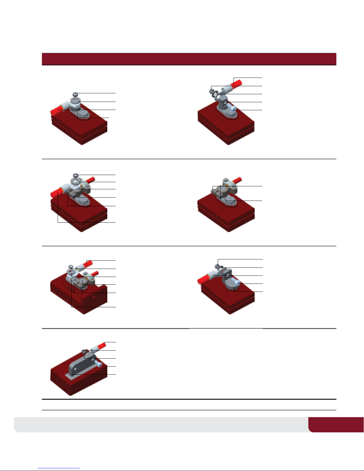
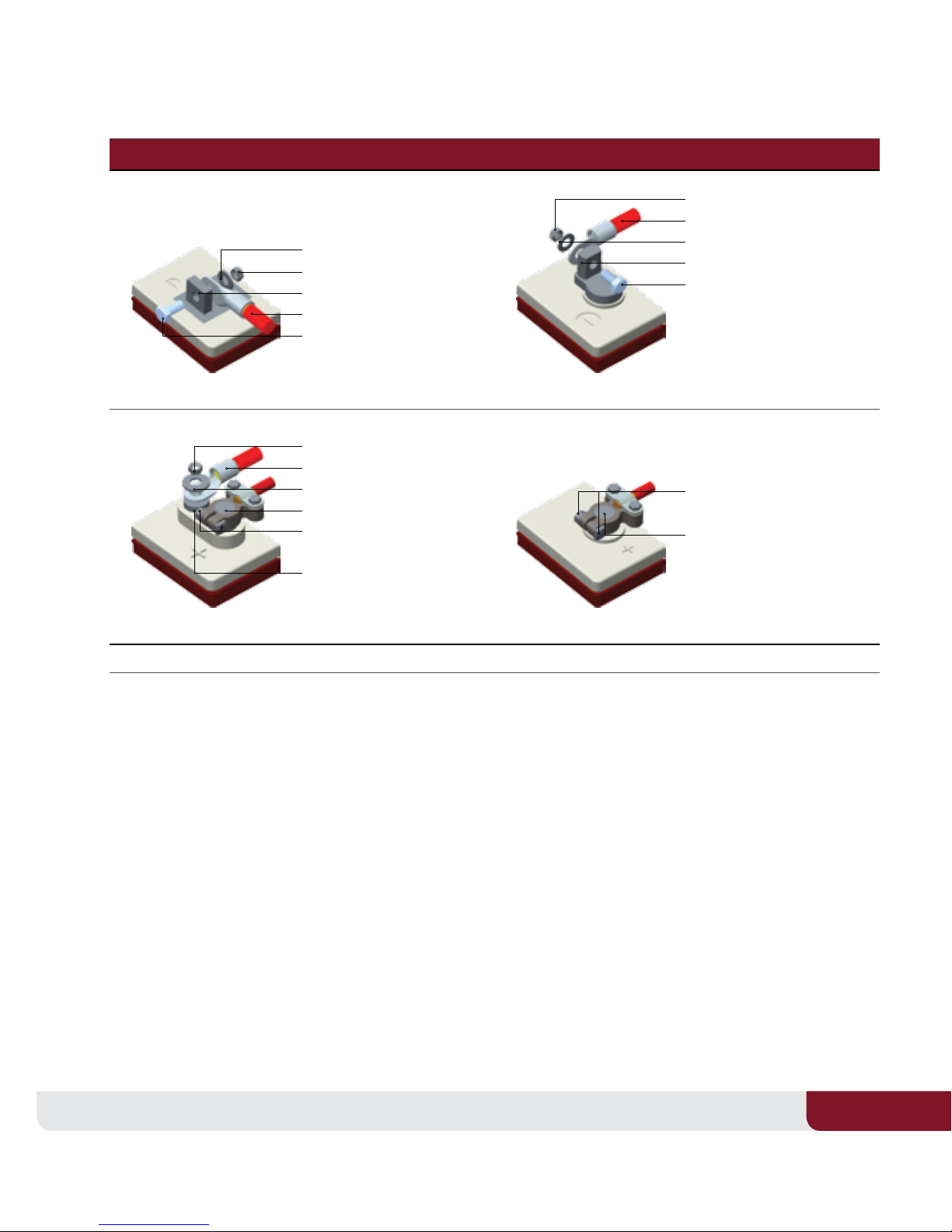
3.1Battery Connections . . . . . . . . . . . . . 6
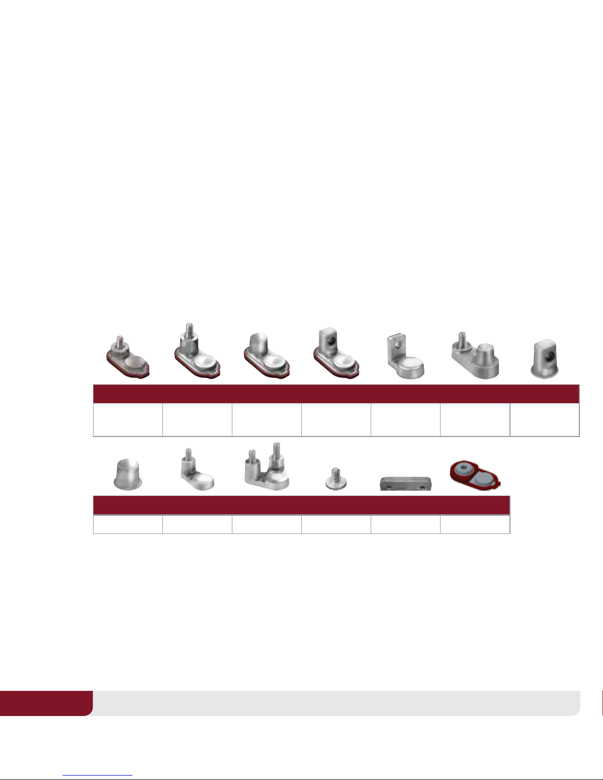
3.2Terminal Types . . . . . . . . . . . . . . . 6
3.4Cable Size . . . . . . . . . . . . . . . . .10
3.5Torque Values . . . . . . . . . . . . . . . .11
3.6Terminal Protection . . . . . . . . . . . . .12
3.7Connecting Batteries to Increase System Power . . .12
3.8Ventilation . . . . . . . . . . . . . . . . .13
3.9Battery Orientation. . . . . . . . . . . . . .13
3.10Battery Environment . . . . . . . . . . . .13
3.11Temperature. . . . . . . . . . . . . . . .13
04 Preventative Maintenance . . . . . . . . 14
4.1Inspection . . . . . . . . . . . . . . . . .14
4.2Watering . . . . . . . . . . . . . . . . .14
4.3Cleaning. . . . . . . . . . . . . . . . . .16
4.4Charging & Equalizing. . . . . . . . . . . . .16
4.4.1Boost Charging . . . . . . . . . . . . . .16
4.4.2Charging . . . . . . . . . . . . . . . .18
4.4.3Equalizing . . . . . . . . . . . . . . . .22
05 Storage . . . . . . . . . . . . . . . . . 24
5.1Storage in Hot Environments . . . . . . . . . .24
5.2Storage in Cold Environments . . . . . . . . .24
06 How to Maximize the Performance of your
Trojan Battery . . . . . . . . . . . . . . 24
07 What to Expect from your Trojan Battery . 25
08 Trouble-Shooting. . . . . . . . . . . . . 26
8.1Preparation for Testing . . . . . . . . . . . .26
8.2On-Charge Voltage Testing . . . . . . . . . . .26
8.3Specic Gravity . . . . . . . . . . . . . . .27
8.4Open Circuit Voltage Testing . . . . . . . . . .27
8.5Discharge Testing . . . . . . . . . . . . . .28
09 Battery Recycling . . . . . . . . . . . . 29
10 Battery Acronyms . . . . . . . . . . . . 30

5
USER’S GUIDE 5
01 Safety
Since batteries deliver large amounts of power that can cause injury and even death, observing safety
rules is of paramount importance. For your safety and the safety of those around you, please observe the
following checklist when working on or around batteries.
Always Never
Always wear protective clothes, gloves & safety goggles Never smoke near batteries
Always use insulated tools when working on batteries Never wear jewelry or other metal objects when working on
or around batteries
Always check connections for proper torque Never make direct contact with the electrolyte (sulfuric acid). If this occurs,
ush with large amounts of water.
Always charge batteries in well-ventilated areas Never place objects on top of batteries, which can cause a short circuit
Always keep sparks and ames* away from batteries Never add acid to a battery
Always use largest cable size of shortest length to minimize voltage drop Never charge a frozen battery
Always ensure plates are covered in water before charging Never charge a ooded battery without securing vent caps on the cells
Always make sure charger is set for the appropriate battery type (ooded,
AGM or gel)
Never charge a battery when the temperature is above 122°F (50°C)
Always charge batteries before installing Never store batteries unless they are fully charged
Always neutralize acid spills with baking soda and water Never leave an acid spill unattended
WARNING Risk of re, explosion, or burns. Do not disassemble, heat above 70° C (160° F),
or incinerate.
02 Equipment Needed
Before installation or maintenance of your batteries, have the following equipment available:
îProper personal protective equipment
(eye protection and acid resistant gloves)
îDistilled or treated water (deionized or
reverse osmosis)
îInsulated wrench
îBaking soda
îTerminal protector spray
îVoltmeter
îHydrometer (deep-cycle
ooded/wet batteries)
îDischarge tester (if available)
îBattery charger

TROJAN BATTERY
6
03 Battery Installation
To ensure you install your batteries properly and safely, please use the following guidelines.
3 .1 Battery Connections
Battery cables provide the link between the batteries, equipment and charging system. Faulty
connections can lead to poor performance and terminal damage, meltdown or re. To ensure proper
connections, please use the following guidelines for cable size, torque values and terminal protection.
3.2 Terminal Types
Below are the various terminal types found on Trojan batteries. Refer to the appropriate terminal type
when determining proper torque in Section 3.5 below.
1ELPT 2EHPT 3EAPT 4EUT 5LT 6DT 7UT
Embedded Low
Prole
Embedded High
Prole
Embedded Auto
Post
Embedded
Universal
L-Terminal Automotive Post
& Stud
Universal
8AP 9WNT 10 DWNT 11 ST 14 IND 15 M6/M8 15
Automotive Post Wingnut Dual Wingnut Stud Industrial 6mm/8mm Insert
3.3 Correct Hardware*Installation
If using at washers, it is very important to ensure the battery cable lug connection is contacting the lead
surface of the terminal, and the washer is placed on top of the wire connection. Do not place washer
between the battery terminal and the battery wire, which creates high resistance and can cause
terminal meltdown. It is important that fasteners be tightened to the appropriate torque for each
terminal type, as dened in Table 2.

7
USER’S GUIDE 7
Flooded
ELPT EUT
EHPT EAPT
DT LT
IND
Images shown reect correct hardware placement. *Hardware not supplied by Trojan Battery Company.
Nut - Torque to 95-105 in-lbs (11-12 Nm)
Washer*
Washer*
AP Connector
Torque to 50-70 in-lbs (6-8 Nm)
Cable Lug
Cable Lug
Terminal
Terminal
Stud Portion
Cable Lug
Nut - Torque to 95-105 in-lbs (11-12 Nm)
Washer*
Terminal
Bolt
Nut - Torque to 95-105 in-lbs (11-12 Nm)
Washer*
Cable Lug
Bolt
Terminal
Cable Lug
Nut - Torque to 100-120 in-lbs (11-14 Nm)
Washer*
Bolt
Terminal
Terminal
AP Connector
Torque to 50-70 in-lbs (6-8 Nm)
Cable Lug
Nut - Torque to 95-105 in-lbs (11-12 Nm)
Washer*
AP Terminal
AP Connector
Torque to 50-70 in-lbs (6-8 Nm)
Stud Terminal

TROJAN BATTERY
8
AGM
LT DT
M6 M8
AP (RELIANT) AP
ST
Images shown reect correct hardware placement. All hardware supplied for Reliant AGM. Hardware for non Reliant AGM is optional.
Nut - Torque to 55-70 in-lbs (6-8 Nm) Nut - Torque to 95-105 in-lbs (11-12 Nm)
Washer Cable LugLock Washer
Cable Lug Lock Washer
Bolt- 20 mm AP Terminal
M8 Terminal AP Connector
Torque to 50-70 in-lbs (6-8 Nm)
Bolt- 16mm - Torque to 85-95 in-lbs (10-11 Nm)
Washer
Lock Washer
Stud Terminal
AP Connector
Torque to 50-70 in-lbs (6-8 Nm)
Lock Washer
Bolt - Torque to 85-95 in-lbs (10-11 Nm)
Washer
Cable Lug
Terminal
Lock Washer
Bolt - Torque to 25-35 in-lbs (3-4 Nm)
Washer
Cable Lug
Terminal
LT Adapter
AP Adapter
Torque to 85-95 in-lbs (10-11 Nm)
M8 Terminal
Nut - Torque to 120-180 in-lbs (14-20 Nm)
Cable Lug
Terminal
AP Connector
Torque to 44-62 in-lbs (5-7 Nm)
Terminal

9
USER’S GUIDE 9
Gel
LT UT
DT AP
Images shown reect correct hardware placement. *Hardware not supplied by Trojan Battery Company.
Washer*
Nut - Torque to 95-105 in-lbs (11-12 Nm)
Cable Lug
Cable Lug
Terminal
Washer*
Washer*
Cable Lug
Terminal
AP Connector
Torque to 50-70 in-lbs (6-8 Nm)
Terminal
AP Connector
Torque to 50-70 in-lbs (6-8 Nm)
Bolt
Bolt
AP Connector
Torque to 50-70 in-lbs (6-8 Nm)
Stud Terminal
AP Terminal
Washer
Cable Lug
AP Connector
Torque to 44-62 in-lbs (5-7 Nm)
Terminal

TROJAN BATTERY
10
3.4 Cable Size
Battery cables should be sized to handle the expected load. Refer to Table 1 for the maximum amps
based on the cable/wire gauge size.
Table 1
Cable/Wire Gauge Size (AWG) Ampacity (amps)
14 25
12 30
10 40
855
675
495
2130
1150
1/0 170
2/0 265
4/0 360
Table values are for cable lengths
less than 6 feet (1829 mm). In
series/parallel battery banks, it
is preferable for all series cables
to be the same length, and all
parallel cables to be the same
length.
For more information refer to the
National Electric Code for correct
cable/wire size, which can be
located at www.nfpa.org.

11
USER’S GUIDE 11
3.5 Torque Values
Tighten all cable connections to the proper specication to make sure there is good contact with the
terminals. Over-tightening terminal connections can cause terminal breakage and loose connections
can result in terminal meltdown or re. Refer to Table 2 for the proper torque values based on the type of
terminal on your battery.
Table 2
Terminal Type Dry Torque (in-lb) Dry Torque (Nm)
Flooded
DWNT, ELPT, EUT, LT, UT, WNT 95 - 105 11 - 12
EAPT, AP 50 - 70 6 - 8
DT, EHPT 50 - 70 (AP Connector)
95 - 105 (Stud Portion)
6 - 8 (AP Connector)
11-12 (Stud Portion)
IND 100 - 120 11 - 14
AGM
M8 85 - 95 10 - 11
AP (Adapter) Reliant 50 - 70 (AP Connector)
95 - 105 (AP Adapter)
6 - 7 (AP Connector)
11 - 12 (AP Adapter)
AP 44 - 62 5 - 7
DT 50 - 70 (AP Connector)
95 - 105 (Stud Portion)
6 - 8 (AP Connector)
11-12 (Stud Portion)
LT (Adapter) 55 - 70 (Nut)
85 - 95 (Bolt)
6 - 8 (Nut)
10 - 11 (Bolt)
M6 25 -35 3 - 4
ST 120 - 180 14 - 20
Gel
AP 50 - 70 6 - 8
LT, UT 95 - 105 11 - 12
DT 50 - 70 (AP Connector)
95 - 105 (Stud Portion)
6 - 8 (AP Connector)
11-12 (Stud Portion)
WARNING Use an insulated wrench when making battery connections.

TROJAN BATTERY
12
3.6 Terminal Protection
Corrosion can build up on terminals if they are not kept clean and dry. To prevent corrosion, after
tightening the fasteners, apply a thin coat of terminal protector spray that can be purchased through
your local battery dealer.
3.7 Connecting Batteries to Increase System Power
You can increase capacity and voltage, or both, by conguring your batteries as follows:
Series Connect Parallel Connect Series/Parallel Connect
Note: maximum of three parallel strings
To increase voltage, connect batteries in
series. This will not increase the system
capacity.
To increase capacity, connect batteries
in parallel. This will not increase the
system voltage.
To increase both voltage and capacity,
connect additional batteries in series
and parallel.
EXAMPLE
Two T-105, 6V Batteries rated at 225AH
Connected in Series
Two T-105, 6V Batteries rated at 225AH
Connected in Parallel
Four T-105, 6V Batteries rated at 225A
Connected in Series/Parallel
Voltage 6V + 6V = 12V System
Capacity = 225AH
Voltage 6V System
Capacity = 225AH + 225AH = 450AH
Voltage 6V + 6V = 12V System
Capacity = 225AH + 225AH = 450AH
Call Tech Support for Additional Congurations

13
USER’S GUIDE 13
3.8 Ventilation
Deep-cycle ooded/wet lead acid batteries release small amounts of gas during usage, particularly
during the charging process. Deep-cycle AGM and gel batteries do release gas, but at a much lower rate
than the ooded types. It is critical to charge batteries in a properly ventilated area. For more assistance in
determining ventilation needs, please contact Trojan Battery Company’s technical support engineers.
3.9 Battery Orientation
Deep-cycle ooded/wet batteries must be placed upright at all times. Fluid in the battery will spill if the
battery is placed on its side or at an angle. Deep-cycle AGM or gel batteries are non-spillable and can be
placed either upright or on their side.
3 .10 Battery Environment
Batteries should be stored and installed in a clean, cool and dry place, keeping water, oil, and dirt away
from the batteries. If any of these materials are allowed to accumulate on the batteries, tracking and
current leakage can occur, resulting in self-discharge and possible short-circuits. Battery chargers should
also be installed in well-ventilated, clean areas that are easily accessible.
3 .11 Temperature
The recommended operating temperature range is between -4°F to 122°F (-20°C to +50°C) with a
humidity of <90%. Elevated battery electrolyte temperatures of >80°F (27°C) will reduce operating life,
while lower battery electrolyte temperatures of <80°F (27°C) will reduce battery performance.
It is important to minimize temperature variations between the cells, therefore, do not arrange the
batteries where they are too tightly packed together which restricts airow. The batteries should have a
minimum of 0.50” (12.7 mm) of space between them to allow for adequate airow.

TROJAN BATTERY
14
04 Preventative Maintenance
4 .1 Inspection
îExamine the outside appearance of the battery. The tops of the batteries and terminal connections
should be clean and dry, as well as free of dirt and corrosion. Refer to Cleaning Section 4.3.
îIf uids are present on the top of a deep-cycle ooded/wet battery, it may mean that the battery is
being over-watered or overcharged. Refer to Watering Section 4.2 for the proper watering procedure.
îIf uid is present on the top of a deep-cycle AGM or gel battery, it may mean that the battery is being
overcharged, which can reduce battery performance and life.
îCheck battery cables and connections. Replace any damaged cables and tighten any loose
connections. Refer to Torque Values Section 3.5.
4.2 Watering (ooded/wet batteries only)
Deep-cycle ooded/wet batteries need to be watered periodically. The
frequency depends on battery usage, charging and operating temperature.
Check new batteries every few weeks to determine the watering frequency for
your application. It is normal for batteries to need more watering as they age.
Water should NEVER be added to deep-cycle AGM or gel batteries.
îUse only distilled or deionized water. Tap water can contain contaminants
that will damage the battery.
îFully charge the batteries prior to adding water. Only add water to
discharged or partially charged batteries if the plates are exposed. In this
case, add just enough water to cover the plates and then charge the
batteries. Once completed, continue with the watering procedure below.
îCheck the electrolyte levels by removing the vent caps and placing them upside down so that dirt
does not accumulate on the underside of the cap. For Plus Series™ batteries, simply ip open the cap.
îIf the electrolyte level is well above the plates, then it is not necessary to add more water.
îIf the electrolyte level is barely covering the plates, add distilled or de-ionized water to a level of
1/8” (3 mm) below the vent well. See right.
îAfter adding water, secure vent caps back onto batteries.
îIf tap water is used, it must be tested to ensure that impurities are within acceptable limits. Refer to
Table 3 for Water Impurity Limits.
Standard Batteries
Plus Series™ batteries

15
USER’S GUIDE 15
Table 3
Recommended Maximum Allowable Impurities in Water for Battery Use
Impurity Parts Per Million Eects of Impurity
Color Clear and “White” -
Suspended Matter Trace -
Total Solids 100 -
Organic and Volatile Matter 50 Corrosion of positive plate
Ammonia 8.0 Slight self-discharge of both plates
Antimony 5.0 Increased self-discharge, reduces life, lower on-charge voltage
Arsenic 0.5 Self-discharge, can form poisonous gas at negative plate
Calcium 40 Increase of positive plate shedding
Chloride 5.0 Loss of capacity in both plates, greater loss on the positive plate
Copper 5.0 Increased self-discharge, lower on-charge voltage
Iron 3.0 Increased self-discharge at both plates, lower on-charge voltage
Magnesium 40 Reduced life
Nickel None Allowed Intense lowering of on-charge voltage
Nitrates 10 Increased sulfation on the negative plate
Nitrites 5.0 Corrosion of both plates, loss of capacity, reduced life
Platinum None Allowed Increased self-discharge, lower on-charge voltage
Selenium 2.0 Positive plate shedding
Zinc 4.0 Slight self-discharge of negative plate

TROJAN BATTERY
16
4.3 Cleaning
Check the battery for cleanliness at regular intervals and keep terminals and connectors free of corrosion.
Terminal corrosion may adversely aect the performance of the battery and present a safety hazard.
îCheck that all vent caps are secured properly on the battery.
îClean the top of the battery, terminals and connections with a cloth or brush, and a solution of
baking soda and water (1 cup of baking soda to 1 gallon of water).
Do not allow cleaning solution to get inside the battery.
îRinse with water and dry with a clean cloth.
îApply a thin coat of terminal protector spray that can be purchased through your local battery dealer.
îKeep the area around batteries clean and dry.
4.4 Charging & Equalizing
4.4.1 Boost Charging
The term boost charging refers to fully charging your batteries before they are used or when they are in
storage.
Flooded Batteries
Two methods can be used to boost charge ooded batteries, either automatically or manually. If
using the automatic method (charger is preprogrammed), simply allow the charger to go through the
complete charge cycle.
If you use the manual method (charger has adjustable settings) follow the steps below:
îBoost charge at CONSTANT CURRENT, without voltage limit, at 3% of C until the voltage stops
increasing for three consecutive hourly readings. If using CONSTANT VOLTAGE, the recommended
boost charge voltage is 2.45 2.58 V/cell with the charger output current limited to 3 - 5% of C.
Using voltages at the lower end of this range will result in an extended boost time.
îThe boost charge is not complete until the specic gravity readings of each cell remain constant over
three successive hourly readings and all cells are gassing freely. If you have questions concerning
boost charging, contact Trojan Battery Company Technical Support.

17
USER’S GUIDE 17
AGM / Gel Batteries
Similarly, two methods can be used to boost your AGM/gel product, automatically or manually. If using
the automatic method (charger is preprogrammed), just allow the charger to go through the complete
charge cycle. Make sure the proper battery type, AGM or gel, is selected on the charger.
If you use the manual method (charger has adjustable settings) follow the steps below:
îBoost charge at a CONSTANT VOLTAGE of (2.40 V/cell) with the current limited to 20% of C.
Example: 20 amps for a battery with a C of 100Ah.
îThe time needed to boost charge the cells can be determined using the equation below.
Depth of discharge (DOD) can be determined using the information in Table 7.
Boost Charge Time in Hours = + 5 Hours
DOD X Capacity at 20Hr Rate
Maximum Charge Current
For example, a 100Ah battery taken down to a 25% depth of discharge (DOD) or 75% state of charge
(SOC) will need to be boost charged for 7½ hours with a 10A charger, or for 6¼ hours with a 20A charger.

TROJAN BATTERY
18
4.4.2 Charging
Proper charging is imperative to maximize battery performance. Both under- or over-charging batteries
can signicantly reduce the life of the battery. Most chargers are automatic and pre-programmed, while
others are manual and allow the user to set the voltage and current values.
AGM and gel batteries should always have temperature compensated charging.
îBatteries should be fully charged after each use. “Use” is dened as at least 30 minutes
of runtime.
îDeep-cycle ooded/wet charging guidelines: Refer to Table 4 and Diagram 4.
îDeep-cycle AGM charging guidelines: There are various ways to charge AGM batteries. For
optimum performance and life, Trojan recommends a 3-step prole as shown in Diagram 5 and
following the guidelines in Table 5.
îDeep-cycle gel charging guidelines: Refer to Table 6 and Diagram 6.
îBefore charging, make sure the charger is set to the appropriate program for deep-cycle ooded/wet,
AGM or gel, depending on the type of battery you are charging.
îLead acid batteries (deep-cycle ooded/wet, AGM or gel) do not have a memory eect and therefore
do not need to be fully discharged before recharging.
îCharge only in well-ventilated areas.
îCheck electrolyte levels in deep-cycle ooded/wet batteries to make sure plates are covered with
water before charging. Refer to Section 4.2.
îCheck that all vent caps are secured properly on the battery before charging.
îDeep-cycle ooded/wet batteries will gas (bubble) towards the end of charge to ensure proper
mixing of the electrolyte.
îNever charge a frozen battery.
îAvoid charging at temperatures above 122°F (50°C).

19
USER’S GUIDE 19
Table 4
Deep-Cycle Flooded/Wet Batteries - Charger Voltage Settings @ 25°C (77°F)
System Voltage 6 Volt 8 Volt 12 Volt 24 Volt 36 Volt 48 Volt
Bulk Charge (2.47 VPC) 7.41 9.88 14.82 29.64 44.46 59.28
Absorption Charge (2.35 – 2.45 VPC) 7.05 – 7.35 9.40 – 9.80 14.10 – 14.70 28.20 – 29.40 42.30 – 44.10 56.40 – 58.80
Finish Charge (2.70 VPC) 8.10 10.80 16.20 32.40 48.60 64.80
Equalize Charge (2.70 VPC) 8.10 10.80 16.20 32.40 48.60 64.80
Float Charge (if desired 2.25 VPC) 6.75 9.00 13.50 27.00 40.50 54.00
The chart below illustrates a typical recharge prole:
Diagram 4
Recommended Deep-Cycle Flooded/Wet Charging Prole
Note: Charging time will vary depending on battery size, charger output, and depth of discharge.
Voltage
(per cell)
Current
(Amps)
2.45V to 2.70V
(@25°C, 77°F)
2.35V to 2.45V
(@25°C, 77°F)
20% 90% 100%
State of Charge (%)
1-3% C20
10-13% C20
Charge Current
Charge Voltage

TROJAN BATTERY
20
Table 5
Deep-Cycle AGM Batteries - Charger Voltage Settings**
System Voltage 6 Volt 8 Volt 12 Volt 24 Volt 36 Volt 48 Volt
Bulk Charge (2.40 VPC) 7.20 9.60 14.40 28.80 43.20 57.60
Absorption Charge (2.35 – 2.45 VPC) 7.05 – 7.35 9.40 – 9.80 14.10 – 14.70 28.20 – 29.40 42.30 – 44.10 56.40 – 58.80
Finish Charge (2.45 VPC) 7.35 9.80 14.70 29.40 44.10 58.80
Float Charge (2.25 – 2.3 VPC) 6.75 9.00 13.50 27.00 40.50 54.00
** AGM batteries should always use temperature compensated charging per the following rule:
5.0 mV per cell / °C or 2.8 mV per cell / °F
Subtract 0.005 volt per cell from the voltage reading for every 1°C above 25°C, or add 0.005 volt per cell for every 1°C
below 25°C. Subtract 0.0028 volt per cell for every 1°F above 77°F, or add 0.0028 volt per cell for every 1°F below 77°F.
The chart below illustrates a typical recharge prole:
Diagram 5
Recommended Trojan Deep-Cycle AGM Charging Prole
Note: Charging time will vary depending on battery size, charger output, and depth of discharge.
Voltage
(per cell)
Current
(Amps)
2.35V to 2.45V
(@25°C, 77°F)
Charge Current
Charge Voltage
20% 80% 100%
State of Charge (%)
Approximately
C20/200
Will increase
with age
20% C20
This manual suits for next models
2
Table of contents
Other Trojan Camera Accessories manuals

Trojan
Trojan 6V-GEL Setup guide

Trojan
Trojan SOLAR INDUSTRIAL Series User manual

Trojan
Trojan TRILLIUM Series User manual

Trojan
Trojan GC2 User manual

Trojan
Trojan GC2 User manual

Trojan
Trojan SINGLE-POINT WATERING KIT Series User manual

Trojan
Trojan GC2 48V User manual

Trojan
Trojan GC2 User manual

Trojan
Trojan TR 12.8-92 Li-Ion User manual