Trojan GC2 User manual

USER’S GUIDE
TROJAN®GC2 48V
LITHIUM-ION BATTERY
© 2021, Trojan Battery Company, LLC

TROJAN BATTERY
2
CONGRATULATIONS
on your purchase from Trojan Battery Company, LLC (“Trojan”),
manufacturers of the world’s most trusted batteries. GC2 Lithium-Ion
batteries are engineered for safety and performance—delivering faster
charge times and longer distances with virtually zero required maintenance.
It’s the next innovation in battery power backed by 100 years of expertise.
We’re proud to continue our tradition of delivering clean, long-lasting and
reliable batteries to power your world.
TROJAN BATTERY
COMPANY WITH
QUALITY SYSTEM
CERTIFIED BY DNV
= ISO 9001:2015 =

3
USER’S GUIDE 3
THIS USER’S GUIDE
was created by Trojan’s application engineers and contains vital information
regarding proper care and maintenance of your new battery. Please read
through this User’s Guide carefully and completely before using your battery.
It will help you achieve optimum performance and long life from your new
investment. If you have any questions concerning safety precautions or
for any assistance in installing or using the battery in your system, contact
Trojan’s technical support engineers at one of the following numbers, or send
us an email through our website at www.trojanbattery.com/tech-support/.
www.trojanbattery.com
800-423-6569 Ext. 3045 / +1-562-236-3045
technical@trojanbattery.com
TECHNICAL SUPPORT

TROJAN BATTERY
4
CONTENTS
1 YOUR TROJAN LITHIUM-ION BATTERY
2 SAFETY
3 EQUIPMENT NEEDED
4 BATTERY INSTALLATION
5 PREVENTIVE MAINTENANCE
6 CHARGING
7 STORAGE AND SHIPPING
8
MAXIMIZING THE PERFORMANCE OF YOUR BATTERY
9 WHAT TO EXPECT FROM YOUR TROJAN LITHIUM-ION BATTERY
10 ELECTRICAL SPECIFICATIONS
11 BATTERY RECYCLING
12 BATTERY ABBREVIATIONS
5
6
7
7
12
12
15
15
15
16
17
17
PAGE
NUMBER

5
USER’S GUIDE 5
1YOUR TROJAN LITHIUM-ION BATTERY
The TR GC2-48-G battery is a deep-cycle lithium-ion battery specifically designed for use in golf carts and similar
personal transportation vehicles with 48V battery packs. Key attributes of the battery include:
îCase size: BCI Group GC2
îNominal Voltage: 51.2V
îCapacity*: 30Ah
îTerminal configuration: M8-1.25 threaded studs
îCommunication Port: CAN Bus SAE J1939
*Temperature, load, state of charge, and battery age can affect battery performance and capacity.
A
F
B C D
E
F
A. Status Button
B. Negative Terminal (M8 size)
C. Battery Status Indicators (SOC)
D. Positive Terminal (M8 size)
E. Communications Port I/II
F. Lifting Brackets

TROJAN BATTERY
6
2SAFETY
ALWAYS NEVER
Always wear proper personal protective equipment (PPE)
(eye protection and gloves).
Never wear jewelry or other metal objects when working on or
around batteries.
Always use insulated tools when working on batteries. Never place objects on top of batteries.
Always check connections for proper torque. Never charge a battery when the temperature is below 32°F (0°C)
or above 113°F (45°C).
Always keep sparks and flames away from batteries. This includes
sources of static electricity. Never store batteries below 30% State of Charge.
Always use short cables of appropriate size to minimize
voltage drop.
Never exceed maximum charging currents for the battery’s
temperature.
Always make sure charger is set as recommended. Never dispose of batteries as household waste. Use recycling
channels in accordance with local, state and federal regulations.
Always charge batteries before installing. Never connect or disconnect terminals from batteries without first
disconnecting loads.
Always make sure chargers are off or disconnected while working
on batteries. Never attempt to open the battery case.
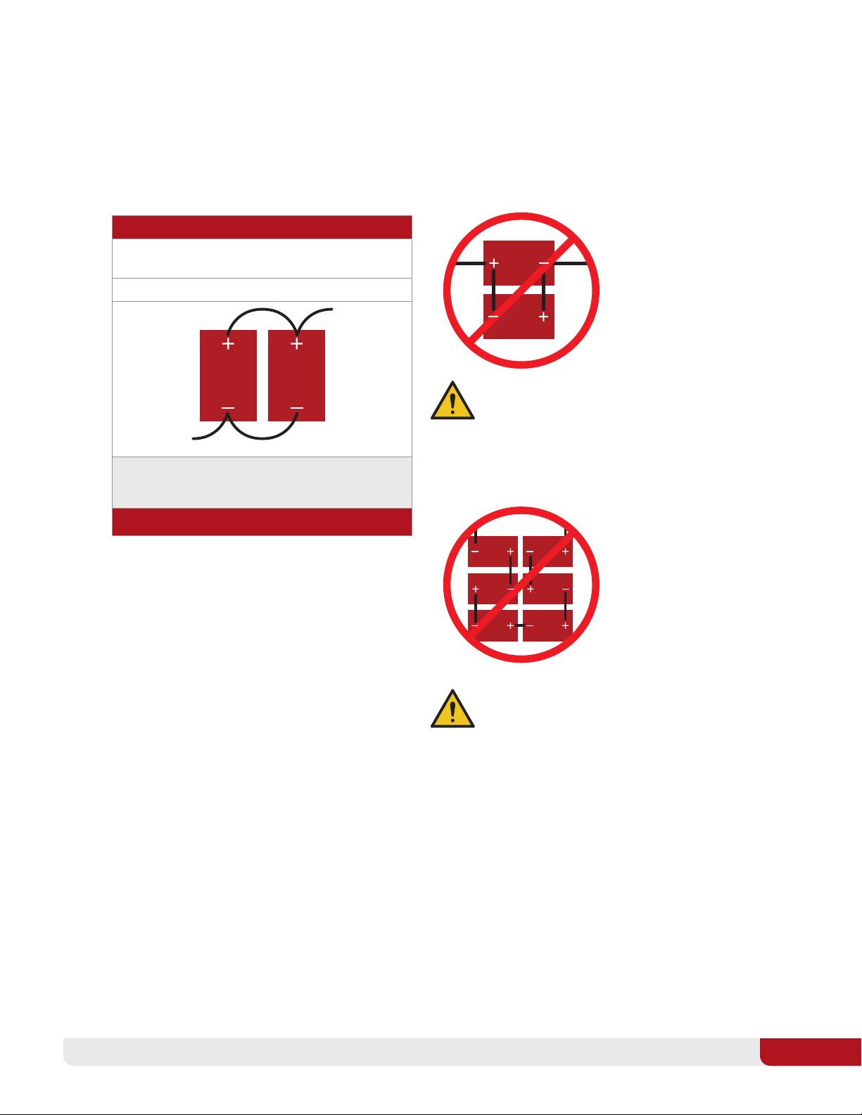
Always add additional TR GC2-48-G batteries in parallel. Never use pressure washers to clean the battery or immerse the
battery in water.
Always use battery lifting strap. Never short-circuit the battery terminals.
Always review product warning labels and
Trojan®GC2 48V Lithium-Ion User’s Guide.
Never physically damage the battery (this includes, without
limitation): Puncturing, dropping, crushing, burning, penetrating,
shaking, hammering, and misconnecting terminals.
Always install batteries while powered off. Never lift by the battery terminals.
Never over-charge or over-discharge the battery.
Never attempt to connect TR GC2-48-G batteries in series.
WARNING! RISK OF FIRE, EXPLOSION OR BURNS. DO NOT DISASSEMBLE,
HEAT ABOVE 140°F 60°C OR INCINERATE.
THE MOST EFFECTIVE FIRE EXTINGUISHER TYPES FOR TROJAN LITHIUMION
BATTERIES ARE CO2OR WATER. SEE SAFETY INSTRUCTIONS.
Trojan®GC2 48V Lithium-Ion batteries are engineered to disconnect from the host system under a variety of
conditions in order to avoid internal damage. When this occurs in equipment using these batteries, all power will
be lost. In certain types of equipment, an abrupt interruption of power can cause undesirable and unexpected
equipment behavior, such as braking loss or sudden braking. The system installer must understand the
consequences of this behavior and ensure that proper system features are in place to avoid potentially harmful
changes in equipment behavior without properly notifying the operator. The system installer assumes all responsibility
and liability for any damages that may occur if these features are not properly implemented. For reference, automatic
safety shutdown modes are described in Section 10.3: “Protection Limits: Automatic Safety Shutdown.”

7
USER’S GUIDE 7
Lithium-ion batteries, including Trojan®GC2 48V Lithium-Ion batteries, weigh substantially less than
lead-acid batteries of comparable capacity. Many types of equipment are designed to utilize the weight of
lead-acid batteries to achieve the manufacturer’s intended weight distribution. If lithium-ion batteries are
installed as replacement batteries in equipment designed to use lead-acid batteries as ballast, the weight
distribution of the equipment could be impacted. The system installer must understand the consequences
of modified weight distribution and ensure that stability remains within a safe range for the intended use.
The proper installation of Trojan batteries may require additional ballast weights or other adjustments or
equipment modifications to ensure stability, safe weight distribution, and safe operation. The improper
installation of Trojan®GC2 48V Lithium-Ion batteries could compromise the weight balance and physical
stability of the equipment leading to unsafe conditions. The system installer assumes all responsibility and
liability for any damages, injuries or accidents that may occur due to degraded stability resulting from an
improper installation, including, but not limited to, failure to safely and properly distribute weight.
3EQUIPMENT NEEDED
Before installation or maintenance of your batteries, have the following equipment available:
îProper personal protective equipment îInsulated tools
(eye protection and gloves) îVoltmeter (optional)
îBattery charger îCables
îBattery lifting strap (recommended) î13mm socket
4BATTERY INSTALLATION
The Lithium-ion battery voltage is 48V for use in 48V vehicles only. Connect batteries in parallel
electrically when installing more than one battery in your vehicle. Be sure to follow the instructions
for parallel installation.
Installing multiple batteries in parallel (See Section 4.5: “Connecting Batteries in Banks”) increases the
driving range and may be required to match the power requirements of the motor controller in your vehicle.
Do not connect batteries in a series string, or the battery may be damaged, or fire may occur.
The installer should verify every battery is off before performing the installation procedure.
See Section 4.10: “Battery Start-Up.” For operation and use, turn the battery back ON using
the status button on each battery.
4.1 INSPECTION AND 12V ACCESSORIES
Check for visible damage including cracks, dents, deformation and other visible abnormalities.
The tops of the batteries and terminal connections should be clean, free of dirt and corrosion, and dry.
If any problems are detected with the batteries, contact Trojan technical support or your battery distributor.
If damage occurred in transit, contact your freight carrier.

TROJAN BATTERY
8
4.1 INSPECTION AND 12V ACCESSORIES CONTINUED
To prevent damage to 12V accessories in the cart, first verify the voltage requirement of accessories like lights or others
items in the vehicle. Then, if needed, the installer can use a voltage reducer to reduce the 48V battery voltage
to 12V or as required. To ensure you install your batteries properly and safely, please use the following guidelines.
4.2 TERMINALS AND TORQUE VALUES
Both the positive and negative terminals of the battery are M8-1.25 x 18mm threaded studs. Ensure that the nuts are
tightened to the proper dry torque of 80-90 in•lbs (9-10Nm). OVER-TIGHTENING TERMINAL CONNECTIONS CAN
CAUSE TERMINAL BREAKAGE, AND LOOSE CONNECTIONS CAN RESULT IN TERMINAL MELTDOWN OR FIRE.
4.3 CORRECT HARDWARE INSTALLATION
If using flat or lock washers, it is very important to ensure the battery cable lug is contacting the top surface of the
terminal, and the washer is placed on top of the lug. DO NOT PLACE A WASHER BETWEEN THE BATTERY TERMINAL
AND THE LUG, AS THIS WILL CREATE HIGH RESISTANCE AND CAUSE EXCESSIVE HEATING OF THE CONNECTION,
WHICH CAN RESULT IN FIRE. If assistance is needed in determining the appropriate hardware configuration, contact
Trojan Battery technical support.
4.4 CABLE SIZE
Battery cables should be sized to handle the expected load and be of sufficient length and flexibility to avoid applying
undesirable mechanical loads on the battery terminals. Refer to Table 1 for the maximum amperage based on
the cable/wire gauge size.
WARNING! USE AN INSULATED WRENCH WHEN MAKING
BATTERY CONNECTIONS.
TABLE 1
Table values are from NEC Table 310.15(B)16 for copper cables
rated at 167°F (75°C), operating at an ambient temperature of no
more than 86°F (30°C). Lengths in excess of 6 feet (1829mm)
may require heavier gauge wire to avoid unacceptable voltage
drop. In parallel battery banks, it is preferable for all cables to be
the same length.
For more information refer to the National Electrical Code for
correct cable/wire size, which can be located at www.nfpa.org.
CABLE/WIRE GAUGE SIZE, AWG mm2 AMPACITY (Amps)
14 (2.08) 20
12 (3.31) 25
10 (5.26) 35
8 (8.36) 50
6 (13.3) 65
4 (21.1) 85
2 (33.6) 115
1 (42.4) 130
1/0 (53.5) 150
2/0 (67.4) 175

9
USER’S GUIDE 9
4.5 CONNECTING BATTERIES IN BANKS
You can increase the cart driving range and battery power capability by connecting multiple batteries together
in parallel electrically as shown in Table 2.
Note: TR-GC2-48 batteries CANNOT be connected in series.
TABLE 2
4.6 VENTILATION
Trojan®GC2 48V Lithium-Ion batteries do not release gas during normal use. There are no specific ventilation
requirements for TR GC2-48-G installations, although sufficient airflow should be provided to prevent
excessive heat build-up.
4.7 BATTERY ORIENTATION
Batteries should be installed only in a vertical orientation with the terminals on top.
PARALLEL CONNECTION
To increase capacity, connect batteries in parallel. This will
not increase the system voltage.
Two 51.2V batteries rated at 30Ah connected in parallel
System Voltage: 51.2V
System Capacity: 30Ah + 30Ah = 60Ah
CALL TECH SUPPORT FOR ADDITIONAL CONFIGURATIONS
WARNING! DO NOT INSTALL
BATTERIES IN REVERSE POLARITY.
THIS MAY PERMANENTLY DAMAGE
THE BATTERY.
WARNING! DO NOT INSTALL
BATTERIES IN SERIES. THIS
MAY PERMANENTLY DAMAGE
THE BATTERY.

TROJAN BATTERY
10
4.8 BATTERY ENVIRONMENT
Batteries should be stored and installed in a clean, cool and dry place, keeping water, oil and dirt away from
the batteries. If any of these materials are allowed to accumulate on the batteries, tracking and current leakage
can occur, resulting in self-discharge and possible short-circuits. Battery chargers should also be installed in
well-ventilated, clean areas that are easily accessible. Relative humidity should be <90%.
4.9 TEMPERATURE
The operating temperature range for discharging TR GC2-48-G batteries is -4°F to 140°F (-20°C to 60°C).
Charging batteries below 32°F (0°C) is prohibited, and charging currents must be reduced below 68°F (20°C).
See the product datasheet for more information on charging current constraints.
Note that battery life diminishes as temperature increases, while capacity diminishes as temperature decreases.
It is important to minimize temperature variations between the batteries. Therefore, avoid restricting airflow by tightly
packing batteries together. The batteries should have a minimum of 0.50” (12.7mm) of space between them to allow
for adequate airflow.
4.10 BATTERY STARTUP
Your battery may be shipped at 50% state of charge or lower. Prior to installation, follow the instructions in
Section 6.2: “Initial Charging.”
Perform the following steps to turn the battery on:
Verify that the battery is either completely disconnected or correctly connected to the equipment it will be powering.
îBe sure that you are able to see the LEDs, then press and hold the status button.
îThe LEDs will successively turn on from left to right until they are all on.
îOnce all LEDs are on, wait another 2 seconds, then release the status button.
îThe battery will perform a self test for about 10 seconds and turn on. Press and release the status button
to verify the green LED is on and the battery is ready to be used.
Perform the following steps to turn the battery off and place it in storage mode:
îPress and hold the status button.
îAll LEDs will turn on, then successively turn off, starting with the green LED.
îOnce all LEDs are off, wait another 2 seconds, then release the status button.
If the battery has been intentionally turned off for shipping or because of a shutoff condition, you can restart it by the
above steps. However, if a condition that causes a shutoff has not been corrected, the battery will shut off again.
See Section 10.3: “Protection Limits: Automatic Safety Shutdown”, for specific explanations of shutdown causes.

11
USER’S GUIDE 11
4.11 INDICATOR LEDs
The Trojan®GC2 48V Lithium-Ion battery features a status push button and indicator LEDs on the top of the case
as illustrated below. After the status button is momentarily pressed, the indicator LEDs will operate as follows:
LED COLOR DEFINITION
Blue Each blue LED represents 25% State of Charge (SOC) as shown in the legend. During charging,
they will flash the SOC once each second.
Red Active alarm (battery disabled)
Green Battery OK
The light will display this color pattern while the button is pressed.
When the battery is charging, the blue LEDs will blink to indicate charging and the increasing state of
charge percentage. When the charging stops, all the LEDs turn off.
4.12 CAN BUS
The battery includes a Controller Area Network (CAN) bus communications interface. The two circular M8 DIN
connectors are on the top of the battery to enable one battery to connect to another battery using CAN bus
cables in a simple daisy chain wiring scheme.
For normal battery operation, the CAN bus feature is not required. The battery operates and protects
autonomously; it does not require any CAN bus communication or external devices such as external controllers,
or other CAN bus-connected batteries to function. Keep the two black caps installed on the two M8 connectors
to protect them from the environment when not used.
Trojan’s field service can retrieve the battery usage history and view status over the CAN bus interface to help
resolve issues or questions.

TROJAN BATTERY
12
5. PREVENTATIVE MAINTENANCE
5.1 INSPECTION
îPower off battery before inspection.
îExamine the outside appearance of the battery. The tops of the batteries and terminal connections
should be clean, dry and free of corrosion.
îCheck battery cables and connections. Replace any damaged cables and tighten any loose connections.
Refer to Section 4.2: “Terminals and Torque Values.”
5.2 CLEANING
Check the battery for cleanliness at regular intervals and keep terminals and connectors free of corrosion.
Terminal corrosion may adversely affect the performance of the battery and present a safety hazard.
îPower off battery before cleaning.
îDisconnect the battery from the charging source and the load.
îClean the top of the battery, terminals and connections with a damp cloth or non-metallic brush.
If the battery is extremely soiled, a household cleaner may be used.
îDry with a clean cloth.
îKeep the area around batteries clean and dry.
6. CHARGING
6.1 BACKGROUND
Trojan®GC2 48V Lithium-Ion batteries may be used in applications where lead-acid batteries have previously been
utilized. Best charging results are obtained by using an appropriate Trojan-recommended charger and charging profile
(algorithm). Refer to documentation on your specific charger for more information.
4.12 CAN BUS CONTINUED
A certified field service technician can update the battery firmware over the CAN bus to add features or enhancements.
The CAN bus interface is galvanically isolated from the internal battery voltages. Therefore, an external power source
is required to turn on and power the field side of the isolated CAN bus. Contact Trojan’s technical support engineers if
you have any questions about the CAN bus interface and its use. See Section 8: “Maximizing the Performance of Your
Battery” for technical support information.

13
USER’S GUIDE 13
6.2 INITIAL CHARGING
Unless your dealer has charged your battery prior to delivery, it will be received at partial state of charge. If
your system uses more than one battery, follow the steps below:
1. Prior to installation, turn each battery on, then measure and record each battery’s voltage.
2. If all voltages are within 0.5 volts of each other, turn them off, proceed with the installation, then follow the
normal charging procedure.
3. If the voltages differ by more than 0.5 volts, each battery should be individually charged, then the
installation can proceed.
6.3 BALANCING
One function of lithium-ion batteries is to maintain balance between each group of cells within
the battery. This allows the battery to deliver full capacity without any cells experiencing an over or
under-voltage condition.
Balancing is performed when a parallel group of cells reaches a specified threshold voltage corresponding to
nearly 100% state of charge (SOC). At that point, the highest-charged cells “bleed down” a small amount to
enable the remaining groups of cells to “catch up.”
6.4 INITIAL CHARGING CYCLES
In systems using more than one (1) battery, new batteries will be slightly unbalanced when they are unpacked
and initially installed. Interruption of individual battery charging current and charge cycling may occur during
the first charging cycle and is considered normal. Allow some extra time during first charging cycle to allow
the batteries to come into balance.
6.5 CHARGING PROFILES
The recommended charging approach is to use an I-E charging profile with a voltage setting of 55.2
to 57.6 VDC. Use of a compatible charging profile is highly recommended to obtain a fully-charged and
balanced battery pack. Other AGM or GEL charging algorithms may be used with varying degrees of
success, depending upon the charger’s specific settings.
Chargers which charge at lower voltages will not harm
the battery, but will not provide a full charge to maximum
capacity. This may affect range and usable lifespan of the
battery.
Chargers which charge at higher voltages will not harm the
battery, but may not provide a full charge because the battery
will shut off as soon as the voltage gets too high. Charger
cycling may result.
Recommended Charger Range 57.6 VDC55.2 VDC

TROJAN BATTERY
14
6.6 CHARGING AT TEMPERATURES BELOW 68°F 20°C
Maximum charging currents must be reduced at temperatures below 68°F (20°C). Measures need to be taken to
ensure that charging currents do not exceed the values shown on the product datasheet. As mentioned previously,
charging is prohibited below 32°F (0°C).
6.7 CHARGING PROCEDURE
îVerify that the battery is correctly hooked up to the charger with the positive wire on the positive (+) terminal and
the negative wire on the negative (–) terminal.
îEnsure the charger is set to run the appropriate profile.
îIf the charger will not run until it detects battery voltage, be sure that the batteries are turned on.
îStart charging, following the charger manufacturer’s instructions.
îAfter the charge has completed, the charger may be shut off and disconnected, or if it remains in a “maintenance
mode” at less than 55.2 VDC, it can remain connected to the battery indefinitely.
6.8 OTHER CHARGING INFORMATION
îChargers which utilize an automatic desulfation or equalization mode are not recommended.
îWhile the battery is being charged, the blue LEDs will flash the current state of charge once each
second. See Section 4.11: “Indicator LEDs,” for interpretation of LED information.
îIf a battery shuts off due to low state of charge, it should be recharged as soon as possible. Failure to do so may
render the battery permanently unusable.
îDepending upon the initial state of charge and the size of the load, even small parasitic loads such as motor
controllers and on-board chargers can fully discharge batteries in as little as a few days. For instance, a 25mA
load amounts to 0.6Ah discharge per day. Be sure to understand the parasitic loads in your application and set
an appropriate charging interval. If the batteries will not be used for extended periods of time, turn them off.

15
USER’S GUIDE 15
7. STORAGE AND SHIPPING
The following tips will help ensure that your batteries emerge from storage in good condition:
îPrior to long-term storage of the battery, fully charge the battery. Storing a discharged battery can result
in permanent damage or decreased run time.
îStore in a cool and dry location, protected from the elements.
îPlace the battery in storage mode to eliminate potential parasitic loads that may discharge the battery.
Perform the following steps to turn the battery off and place it in storage mode:
îPress and hold the status button for the entire sequence below.
îAll LEDs will turn on, then successively turn off, starting with the green LED.
îOnce all LEDs are off, release the status button after 2 more seconds.
îWhen batteries are taken out of storage they should be given an initial charge prior to use as
outlined in Section 6.
8. MAXIMIZING THE PERFORMANCE OF YOUR BATTERY
îFollow all the procedures in this User’s Guide for proper installation, maintenance and storage.
îIf you have any questions or concerns about battery care, please contact Trojan’s technical support
engineers at 800-423-6569 Ext. 3045 or +1-562-236-3045 before a problem develops.
9. WHAT TO EXPECT FROM YOUR TROJAN LITHIUM-ION BATTERY
îYour Trojan®GC2 48V Lithium-Ion battery will deliver rated capacity when it is new. No “break-in”
period is required.
îWhen operating batteries at low temperatures, they will deliver less than the rated capacity.
îWhen operating batteries at high temperatures, battery life will be reduced.
îThe life of a battery is difficult to predict and will vary by application, frequency of usage and load
characteristics.
IF YOU SHIP THIS BATTERY, THERE ARE SEVERAL STATE, FEDERAL AND INTERNATIONAL LAWS, RULES, REGULATIONS
AND REQUIREMENTS REGARDING LITHIUM BATTERIES THAT YOU MUST COMPLY WITH. YOU MUST UTILIZE A QUALIFIED
SHIPPING AGENT PROPERLY CERTIFIED FOR HAZARDOUS MATERIALS (“HAZMAT”) SHIPMENTS.

TROJAN BATTERY
16
10. ELECTRICAL SPECIFICATIONS
10.1 CHARGING
The charging and discharging current limits in the tables below are for one battery. Installing and electrically
connecting batteries in parallel increases the current limits. For example, two batteries connected in parallel
effectively doubles the current values in the tables below. Adding more batteries increases the driving range,
current, and power capability.
10.3 PROTECTION LIMITS: AUTOMATIC SAFETY SHUTDOWN
As outlined in the following table, Trojan®GC2 48V Lithium-Ion batteries will automatically shut down under excessive
use conditions in order to prevent damage to the battery and connected equipment. This will generally result in total
loss of power to equipment.
Systems must be implemented and precautions must be taken to ensure that sudden loss of power does not result in
hazardous system behavior.
DISCHARGING INFORMATION
Discharge Current (max. continuous) 30A
Discharge Current (time < 30 seconds) 100A
Discharge Current (time < 2 seconds) 155A
Discharge Current (time < 0.2 seconds) 175A
10.2 DISCHARGING
CHARGING INFORMATION
Recommended Charging Voltage 55.2 to 57.6V
Recommended Float Voltage 55.2V
Charge Voltage Cutoff 58.4V
Peak Charge Current (max.) 75A for 0.5 seconds
Charge Current (max. Continuous) @ Temperature
< 32°F (0°C) 0A
32°F to 50°F (0°C - 10°C) 10A
50°F to 68°F (10°C - 20°C) 17A
68°F to 113°F (20°C - 45°C) 34A
> 113°F (45°C) 0A

17
USER’S GUIDE 17
11. BATTERY RECYCLING
Trojan®GC2 48V Lithium-Ion batteries are recyclable and should not be disposed of as household or landfill
waste. If you need assistance in recycling your battery, contact your dealer or Trojan’s technical support
engineers as outlined at the front of this manual.
12. BATTERY ABBREVIATIONS
AS NOTED IN SECTION 2: “SAFETY,” THE SYSTEM INSTALLER ASSUMES ALL
RESPONSIBILITY AND LIABILITY FOR ANY DAMAGES THAT MAY OCCUR DUE
TO SUDDEN LOSS OF POWER.
PROTECTIVE SHUTOFF AND RESTART CONDITIONS
SHUTOFF RESTART OTHER RESTART CONDITIONS
Over Voltage Any cell voltage > 3.74V Battery voltage > 59.9V All cell voltages < 3.64V Battery voltage < 58.2V Load attached and discharging
Low Voltage Any cell voltage < 2.53V Battery voltage < 40.5V All cell voltages > 2.63V Battery voltage > 42.1V Charger attached and charging
Short circuit current 660A instantaneously No automatic restart Push and hold the status button
to clear red LED
Over Temperature Discharge 140°F (60°C) 131°F (55°C)
Over Temperature Charge 113°F (45°C) 104°F (40°C)
Under Temperature
Discharge -4°F (-20°C) 14°F (-10°C)
Under Temperature Charge 32°F (0°C) 41°F (5°C)
Automatic Sleep/
Storage Mode
No use for 30 days or 5 days if the battery state
of charge is lower than 24% No automatic restart Push and hold the status button
to manually wakeup the battery
AAmpere M6/M8 6mm/8mm terminal
Ah Ampere-hour SOC State of Charge
AWG American Wire Gauge T Temperature
°C Degrees Celsius VVolt
DOD Depth of Discharge VDC Volts DC
°F Degrees Fahrenheit

TROJAN BATTERY
18
NOTES

19
USER’S GUIDE 19

would like to thank you for selecting our battery. With close to 100 years of
experience, Trojan Battery is the world’s most trusted name in deep-cycle
battery technology backed by our outstanding technical support. We look
forward to serving your battery needs.
FAILURE TO ABIDE BY THE CARE AND MAINTENANCE REQUIREMENTS OUTLINED HEREIN MAY RESULT
IN VOIDING THE WARRANTY, AS APPLICABLE.
This publication is protected by copyright and all rights are reserved. No part of it may be reproduced or
transmitted by any means or in any form, without prior consent in writing from Trojan Battery Company, LLC.
Trojan Battery Company and the Trojan Battery logo are registered trademarks of Trojan Battery Company.
© 2021 Trojan Battery Company, LLC. All rights reserved. Trojan Battery Company is not liable for direct,
indirect, special, exemplary, incidental or consequential damages that may result from any information
provided in or omitted from this manual, under any circumstances. Trojan Battery Company reserves the
right to make adjustments to this manual at any time, without notice or obligation.
12380 CLARK STREET, SANTA FE SPRINGS, CA 90670
TROJAN BATTERY COMPANY
TRO1044_GC2_UsersGuide_072321
Do not mix with lead-acid batteries when recycling
800-423-6569 Ext. 3045 / +1-562-236-3045
technical@trojanbattery.com
TECHNICAL SUPPORT
800.423.6569 +1.562.236.3000
TROJANBATTERY.COM
Other manuals for GC2
2
This manual suits for next models
1
Table of contents
Other Trojan Camera Accessories manuals

Trojan
Trojan SOLAR INDUSTRIAL Series User manual

Trojan
Trojan GC2 User manual

Trojan
Trojan GC2 User manual

Trojan
Trojan SINGLE-POINT WATERING KIT Series User manual

Trojan
Trojan Flooded User manual

Trojan
Trojan TR 12.8-92 Li-Ion User manual

Trojan
Trojan TRILLIUM Series User manual

Trojan
Trojan 6V-GEL Setup guide

Trojan
Trojan GC2 48V User manual