TROMMELBERG TST40G User manual
USER MANUAL TST40G, V15.01 page | 1
Technical changes, misprints and errors are reserved.
User Manual
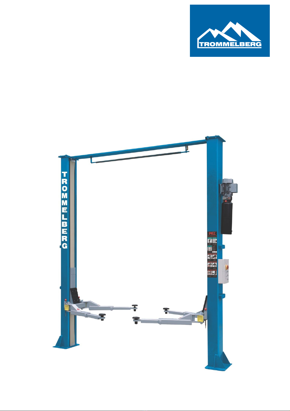
4 Ton Two Post Lift
Model: TST40G, with upper synchronization

USER MANUAL TST40G, V15.01 page | 2
Technical changes, misprints and errors are reserved.
Table of contents
1. Precaution Page 3-5
1.1. Important information Page 3
1.2. Qualified personnel Page 3
1.3. Danger notices Page 4
1.4. Training Page 4
1.5. Warning signs Page 5
2. Overview of the lift Page 6-7
2.1. General description Page 6
2.2. Technical specifications Page 6
2.3. Construction of the lift Page 7
3. Installation instructions Page 8-15
3.1. Preparations before installation Page 8
3.2. Precautions for installation Page 8
3.3. Installation Page 9-15
3.4. Items to be checked after installation Page 15
4. Operation instructions Page 16-19
4.1. Precautions Page 16
4.2. Flow chart for operation Page 17
4.3. Operation instructions Page 18-19
5. Troubleshooting Page 20-21
6. Maintenance Page 22-23
7. Annex Page 24-27
7.1. Packing list Page 24
7.2. Overall diagram Page 25
7.3. Hydraulic working system Page 26
7.4. Wire connection diagram of locking system Page 26
7.5. Wiring diagram Page 27

USER MANUAL TST40G, V15.01 page | 3
Technical changes, misprints and errors are reserved.
1. Precaution
The manual is an integral part of the lift, which it should always accompany even if
the unit is sold. The manual, must be kept in the vicinity of the lift in an easily
accessible place so that the operator and maintenance staff must be able to locate
and consult the manual quickly at any time.
ATTENTIVE AND REPEATED READING OF SAFETY INSTRUCTION, WHICH
CONTAINS IMPORTANT INFORMATION AND SAFETY WARNINGS, IS
PARTICULARLY RECOMMENDED.
1.1. Important information
We will offer one-year's quality warranty for the whole machine, during which
any quality problem will be properly solved to the user's satisfaction.
We will not take any responsibility for whatever bad consequence resulted
from improper installation and operation, overload running or unqualified
ground condition. This 2-posts lift is specially designed for lifting motor
vehicles that weight is within its outmost lifting capacity. Users are not
allowed to use it for any other purposes. Otherwise, we will not bear any
responsibility for accidents or damages of the lift. Make sure to pay careful
attention to the label of the lifting capacity attached on the lift and never try to
lift cars with its weight beyond. Read this manual carefully before operating
the machine so as to avoid economic loss or personnel injuries, incurred by
wrong operation. Without professional advice, users are not permitted to
make any modification to the control unit or the mechanical unit.
1.2. Qualified personnel
- Only qualified staff, who have been properly trained, can operate the lift!
- Electrical connection has to be done by a qualified electrician!

USER MANUAL TST40G, V15.01 page | 4
Technical changes, misprints and errors are reserved.
1.3. Danger notices
- Do not install the lift on asphalt surface.
- Read and understand all safety warnings before operating the lift.
- The lift must not be used outside!
- Keep hands and feet away from any moving parts. Keep feet clear of the
lift during the lowering process!
- Do not wear unfit clothes such as large clothes with flounces, ties, etc.
which could be caught by moving parts of the lift.
- Always keep the lift and the lifting area clean and free of tools, parts,
debris etc.
- Do not exceed the max. lifting capacity of the lift!
- Always insure the safety latches are engaged before any attempt to work
near or under the vehicle
- Only use the vehicle manufacturer´s recommended lifting points!
- Check at any time the parts of the lift to ensure the agility of moving parts
and the performance of synchronization. Ensure regular maintenance and
if anything abnormal occurs, stop using the lift immediately and contact
your dealer/technician for help.
- Lower the lift to its lowest position and do remember to cut off the power
source when the service is finished.
- Do not modify any parts of the lift without the manufacturer´s approval!
- If the lift is not in use for a long time, lower it to its lowest position, cut off
the power source, empty the oil tank and lubricate all the moving parts
with hydraulic oil!
- The standard lift version may not be installed and commissioned in the
vicinity of explosives or flammable liquids.
- The standard lift version may not be installed and commissioned outdoors
or in moist rooms (e.g. car wash).
1.4. Training
Only these qualified people, who have been properly trained, can operate the
lift.
USER MANUAL TST40G, V15.01 page | 5
Technical changes, misprints and errors are reserved.
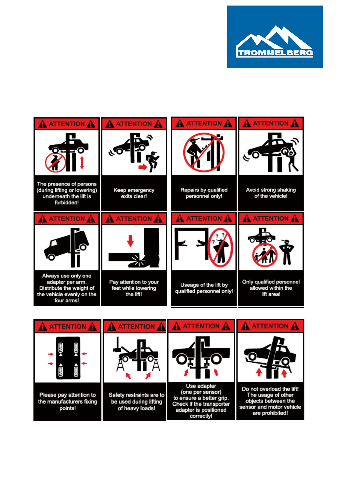
1.5. Warning signs
All the safety warning signs attached on the lift are for the purpose of drawing
the user´s attention to the safety operation. The labels must be kept clean
and need to be replaced when they are worn-out or have been damaged.
Read the explanations of the labels carefully and try to memorize them.
USER MANUAL TST40G, V15.01 page | 6
Technical changes, misprints and errors are reserved.
2. Overview of the lift
2.1. General description
This two post lift is composed of posts, carriages, lifting arms, cylinders and
motor unit etc. It is driven by an electro-hydraulic system. The gear pump
delivers hydraulic oil to the cylinders and pushes its piston upwards. The
piston drives the chain to raise the carriage and the lifting arms. During the
lifting process, the safety latch will automatically and firmly bite with the safety
teeth block in the posts. Therefore, no slipping will happen in case of the
hydraulic system breaks down.
Safety structure
2.2. Technical specifications
Model
Lifting capacity
Full rise time
Full rise
Height
Width
Inside columns
TST40G
4000kg
50s
1900mm
3605mm
3426mm
2800mm
USER MANUAL TST40G, V15.01 page | 7
Technical changes, misprints and errors are reserved.
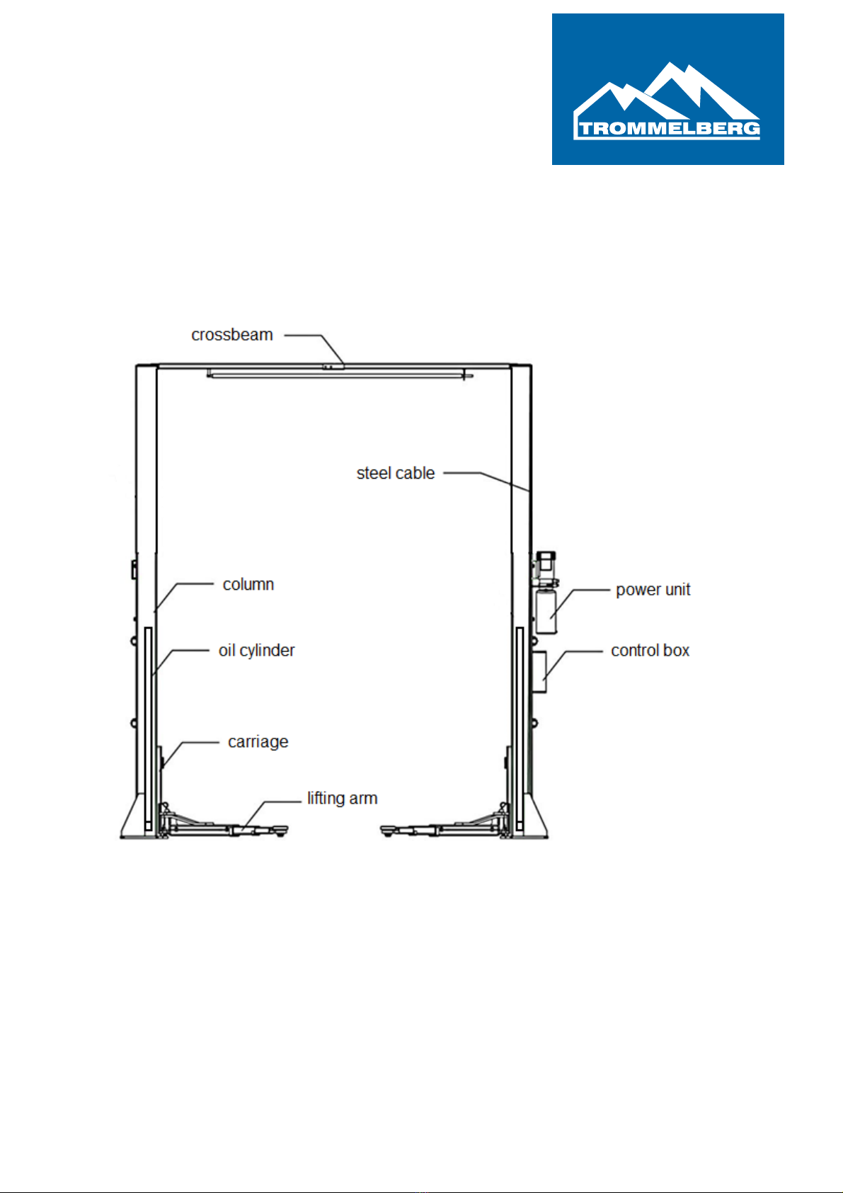
2.3. Construction of the lift

USER MANUAL TST40G, V15.01 page | 8
Technical changes, misprints and errors are reserved.
3. Installation instructions
3.1. Preparations before installation
- Prepare the needed tools and equipment:
oAppropriate lifting equipment
oAnti-abrasion hydraulic oil
oRotary hammer drill
oChalk and tape measure, magnetic plumb
oSockets and open wrenches, a set of inside hex wrenches,
screwdrivers
oHammer, sharp nose pliers
oSocket spanners Ø 17, 19 and 22
- Check that all parts are in the packages (refer to Annex1 –packing list)
- Check the ground conditions of the installation site
oThe lift should be fixed on a smooth and solid concrete ground with
its strength more than 3000PSI (2.1kg/mm³), tolerance of flatness
less than 5mm and minimum thickness of 200mm. In addition,
newly built concrete ground must undergo more than 28 days of
cure and reinforcement!
3.2. Precautions for installation
- Make sure that the two posts are paralleled and vertical to the ground
- The joints of the oil hose and steel cable must be firmly connected in order
to avoid the looseness of the steel cable and leakages of the hydraulic
system
- All bolts should be firmly screwed tight
- DO NOT PLACE ANY VEHICLE ON THE LIFT DURING TRIAL RUNS!

USER MANUAL TST40G, V15.01 page | 9
Technical changes, misprints and errors are reserved.
3.3. Installation
Step 1:
- Remove the packaging, take out the carton with accessories and cover
plate
Step 2:
- Put something supporting between the two posts or suspend one of the
posts by a crane and then remove the bolts on the package
- Attention: Please pay special attention to not let the post fall down, or it
may cause injuries or bring damages to the accessories, fixed in the post!
Step 3:
- When the first post has been taken away, place something supporting
under the second post and then remove the remaining bolts on the
package
Step 4:
- Determine the exact place of installation of the lift
oUnpack the posts and decide on which side you want to have the
power unit and controls
oDraw an outline of the base plate on the ground with chalk and
ascertain the position for the posts (Annex 7.2. Overall diagram)
Step 5:
- Erect the posts, power side first and then the other post
- Drill anchor holes for the expansion bolts (not included) on the ground with
an electrical drill
- MAKE SURE TO DRILL 100% VERTICALLY!
- After the holes have been drilled, remove thoroughly the debris and dust
and ascertain that the post stay upon the circle, previously drawn by chalk
USER MANUAL TST40G, V15.01 page | 10
Technical changes, misprints and errors are reserved.
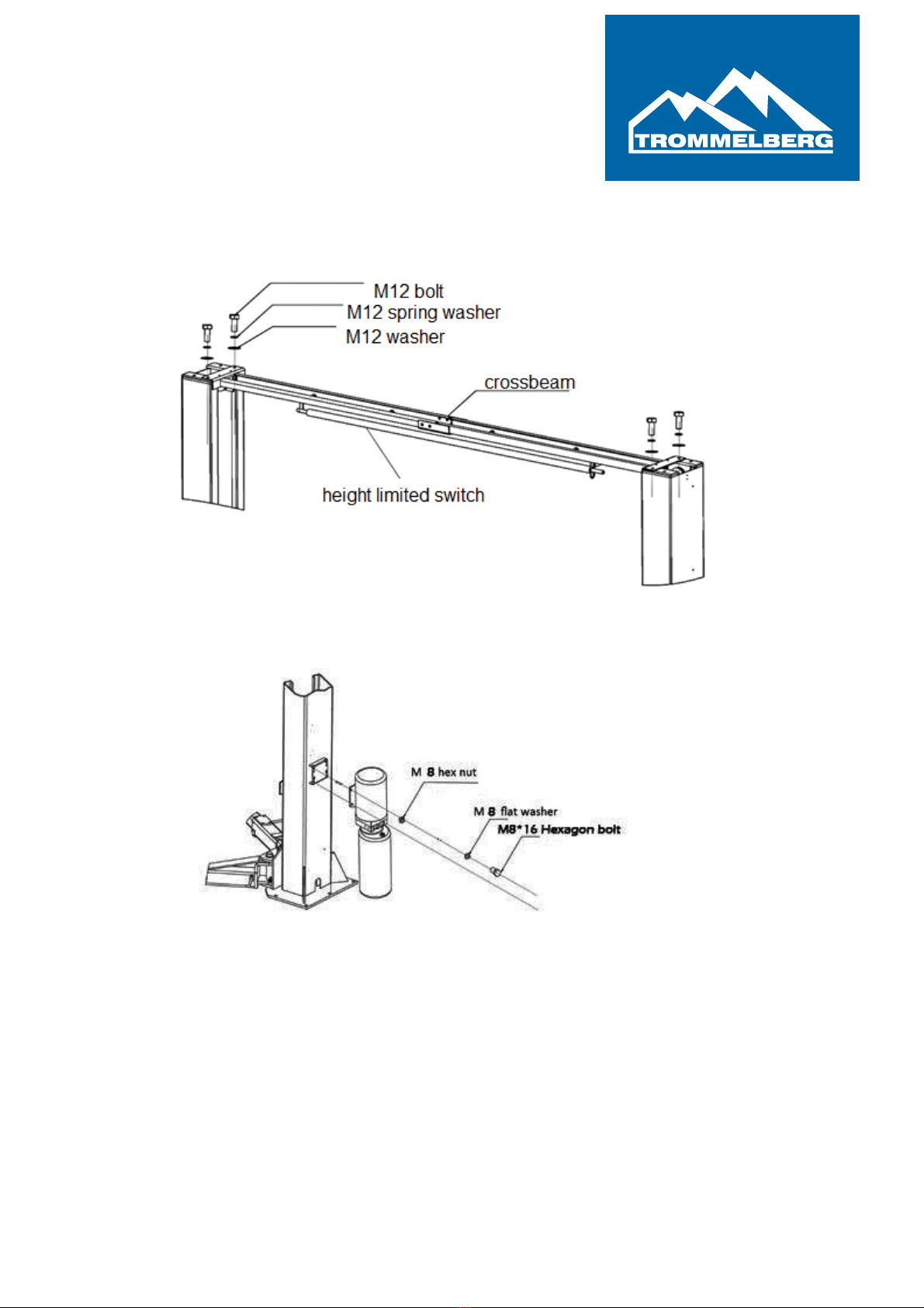
Step 6:
- Installation of the crossbeam:
oAfter the columns are erected and aligned, mount the crossbeam
according to the following drawing:
Step 7:
- Mount the power unit onto the power side post
USER MANUAL TST40G, V15.01 page | 11
Technical changes, misprints and errors are reserved.
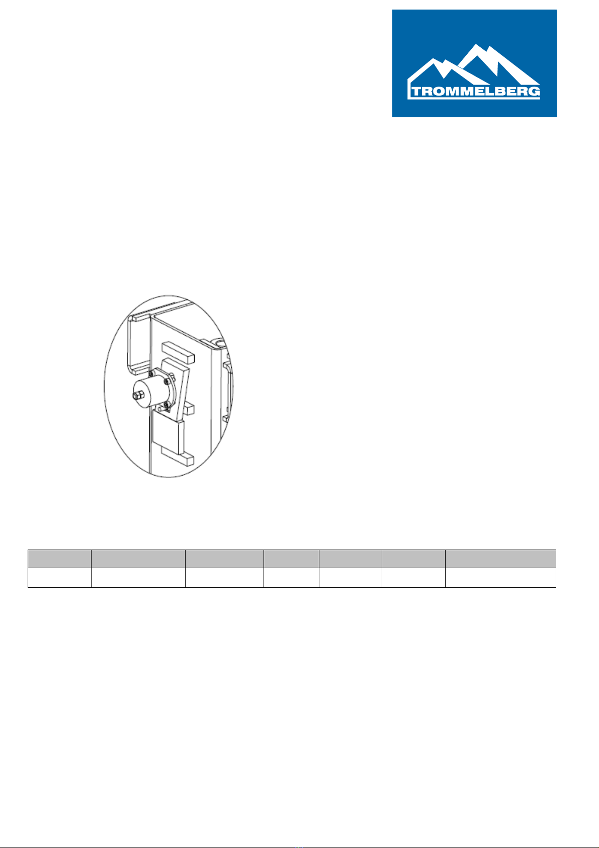
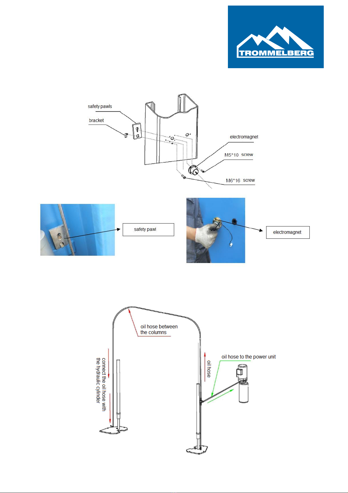
Step 8:
- Install the safety pawls, electromagnets and the corresponding protective
covers
Step 9:
- Installation of the hydraulic hoses
oConnect the oil hoses as shown in the following diagram
USER MANUAL TST40G, V15.01 page | 12
Technical changes, misprints and errors are reserved.
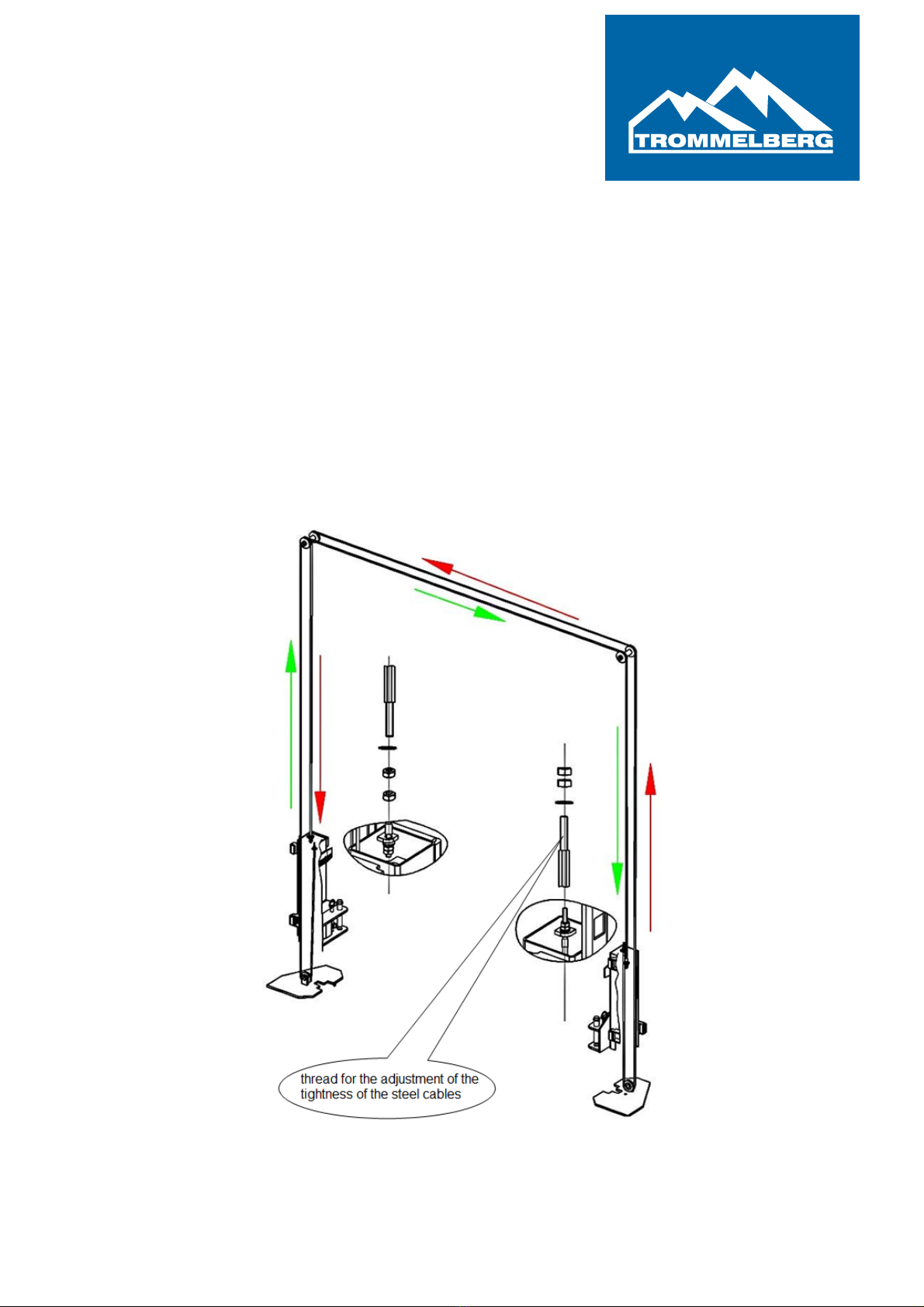
Step 10:
- Installation of the steel cables
oRaise the carriages on both sides to approx. 30 –50cm height
above the ground
oThe carriages have to be on exactly the same height!
oMake sure that the safety pawls are locked, to avoid accidents
and/or injuries.
oAfter the cables being fixed, adjust and make the cables at both
sides be with the same tightness which could be judged by the
sound emitted during the lifting process
oMake necessary adjustments after trial runs
oMANDATORY: lubricate the lift after installation
USER MANUAL TST40G, V15.01 page | 13
Technical changes, misprints and errors are reserved.
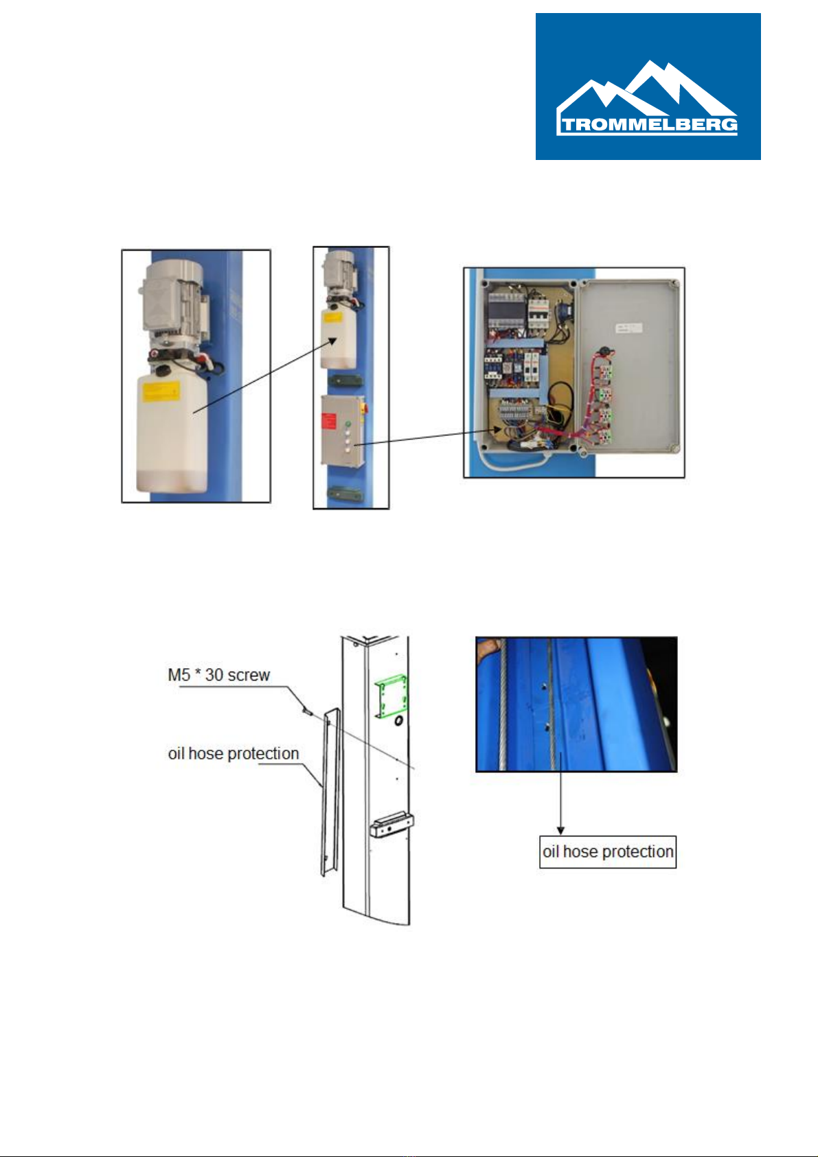
Step 11:
- Installation of the control box
oMount the control box on the power side column
oConnect the power source according to the wiring diagram (page _)
Step 12:
- Installation of the oil hose protection (on both columns) according to the
following picture

USER MANUAL TST40G, V15.01 page | 14
Technical changes, misprints and errors are reserved.
Step 13:
- Installation of the lifting arms
oConnect the lifting arm and the carriage by shafts
oInstall the lifting arms onto the carriages and ensure the arm lock
will work

USER MANUAL TST40G, V15.01 page | 15
Technical changes, misprints and errors are reserved.
Step 14:
- Fill the oil tank with hydraulic oil
- The volume of the oil tank is approx. 10L, to ensure the lift can work
normally, the amount of oil in the tank should at least reach 80% of its total
volume
Attention: For environment protection, dispose the any used oil in a
properway, according to your local regulations!
Step 15:
- Trial run:
oRefer to the operation instructions in advance and keep in mind that
no vehicle is on the lift in the process of a trial run
oCheck and ensure that all the connections are in good condition
oNO VEHICLE ON THE LIFT DURING TRIAL RUNNING!
3.4. Items to be checked after installation
Check items
YES
NO
1
Are the posts vertical to the floor?
2
Are the two posts parallel to each other?
3
Is the oil hose well connected?
4
Is the steel cable well connected?
5
Are all lifting arms fixed tight?
6
Are electrical connections right?
7
Are the rest joints firmly tightened?
8
Are all moving parts lubricated?
(Chapter 6 maintenance)

USER MANUAL TST40G, V15.01 page | 16
Technical changes, misprints and errors are reserved.
4. Operation instructions
4.1. Precautions
- Check all joints of the oil hoses, only when there is no leakage you can
start to work with the lift.
- The lift must not be used if its safety devices has any malfunctions!
- The machine must not raise or lower an automobile, if its center of gravity
is not positioned midways between the lifting arms. Otherwise, the
manufacturer will not bear any responsibility for any consequences
resulted thereby!
- Always keep the lift and the lifting area clean and free of tools, parts,
debris etc.
- When the lift has raised the vehicle to the desired height, switch off the
power, to prevent any mal-operation done by unauthorized people.
- Make sure that the safety lock of the lift is properly locked, before you start
to work under the vehicle!
- Do not allow anyone to stay in the lifting area during raising and lowering
cycles.
- Closely watch the vehicle and the lift during raising and lowering cycles.
- Only use the lift for its intended purpose.
- Climbing up the raised lift or vehicle is prohibited!
- Comply with the applicable accident prevention regulations.
- Do not overload the lift. The rated load capacity is indicated on the lifts
nameplate.
- Only use the vehicle manufacturer´s recommended lifting points!
- Use caution when removing or installing heavy components
(center-of-gravity displacement)!

USER MANUAL TST40G, V15.01 page | 17
Technical changes, misprints and errors are reserved.
4.2. Flow chart for operation
Raising Lowering
Start Start
Press the “UP” button Press the “DOWN” button
Motor drives the gear pump The lift will first raise a little
Cylinder piston drives the chain And then begins to lower
Chain drives the carriage The lift is lowered
Carriage begins to raise
The lift is raised
USER MANUAL TST40G, V15.01 page | 18
Technical changes, misprints and errors are reserved.
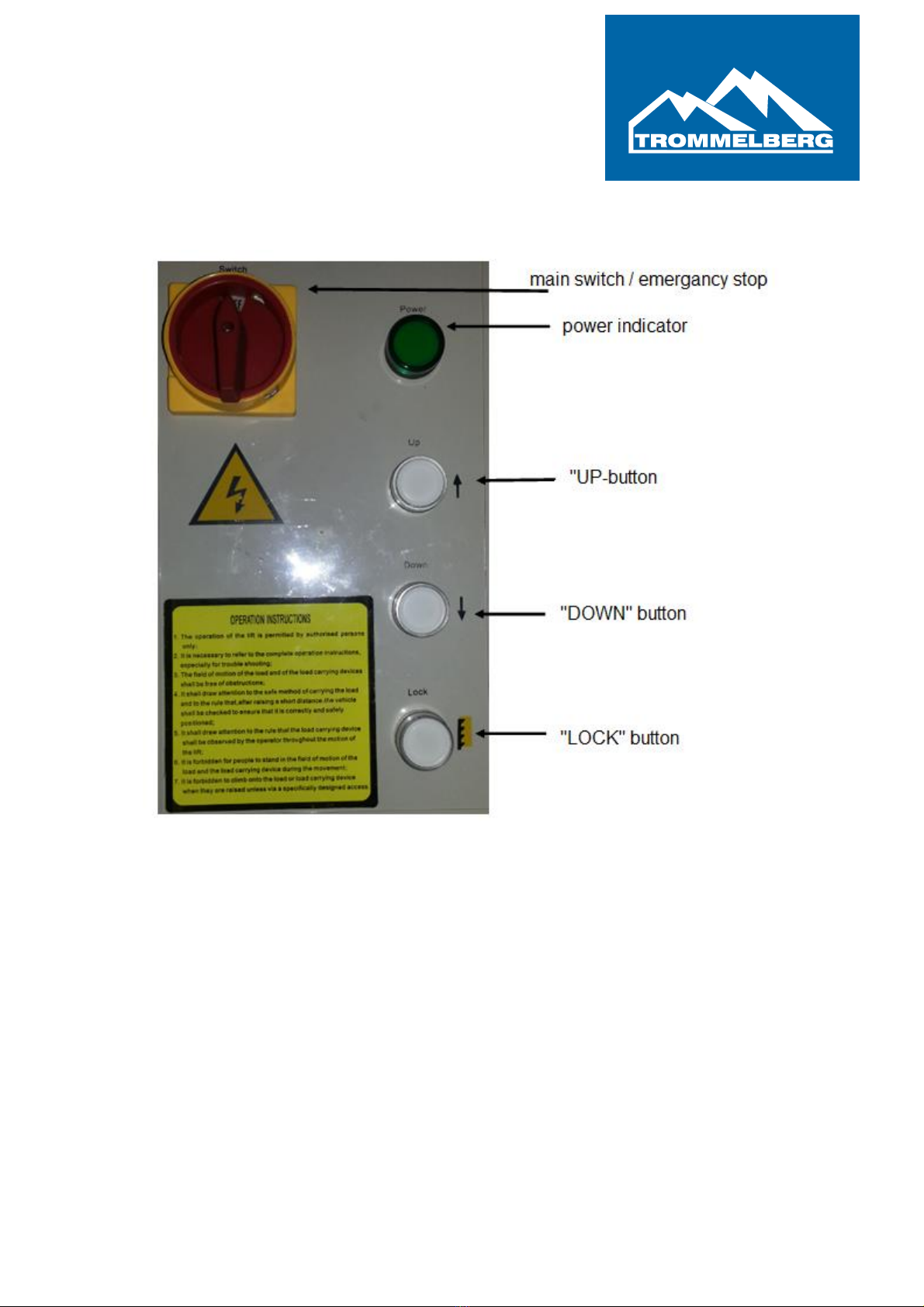
4.3. Operation instructions
IN CASE OF EMERGENCY PRESS THE “EMERGENCY STOP” BUTTON!
(The main switch also serves as emergency off switch)

USER MANUAL TST40G, V15.01 page | 19
Technical changes, misprints and errors are reserved.
Step 1: Raise the lift
a. Make sure you have read and understood the user manual before
operation.
b. Position the vehicle midways between the two posts.
c. Adjust the lifting arms until they reach the vehicle manufacturer´s
recommended lifting points of the vehicle to be lifted and make sure that
the center-of gravity of the vehicle is in the center of the lifting arms.
d. Connect the power supply as per the requirements on the nameplate
attached, and switch on.
e. Press and hold the “UP” button on the control box until the pads of the
lifting arms reach the vehicle manufacturer´s recommended lifting points
and check the correct position of the lifting pads.
f. Keep on raising the vehicle to let it have a bit of clearance from the ground
and check again the stability of the vehicle and the correct position of the
lifting arms.
g. Raise the vehicle to the desired height and check if its position is safe and
stable.
Step 2: Lock the lift
a. Press and hold the “LOCK” button, to lock the safety latch.
b. Now you can start the maintenance or repair work underneath the vehicle.
Step 3: Lower the lift
a. Press and hold the “DOWN” button in the control box to start the lowering
cycle.
b. The lift will first raise a little, in order to unlock the safety latch. Then the lift
will begin to lower.
c. After the lift has reached its lowest position pull out the lifting arms from
underneath the vehicle and clear up all obstacles.
d. Move the vehicle out of the lifting area.

USER MANUAL TST40G, V15.01 page | 20
Technical changes, misprints and errors are reserved.
5. Troubleshooting
ATTENTION: If the problem could not be fixed by yourself, please do not hesitate
to contact your local dealer for help.
Problems can be judged and solved much faster if more details or pictures can
be provided.
ERROR
REASON
REMEDY
Abnormal noise
Abrasion exists on inside surface of the
posts.
Lubricate the inside of the posts.
Trash in the post.
Clear the trash
Motor does not
run and will not
raise
The wire connection isloose.
Check and make a good
connection.
The motor is blown.
Replace it.
The limit switch is damaged or the wire
connection is loose.
Connect it or adjust or replace
the limit switch.
Motor runs but
will not
raise
The motor run in reverse.
Check the wire connection.
Overflow valve is loose orjammed.
Clean or adjust it.
The gear pump is damaged.
Replace it.
Oil level is too low.
Add oil.
The oil hose became loose or dropped
off.
Tighten it.
The cushion valve became loose or
jammed.
Clean or adjusts it.
Carriages go
down slowly
after being
raised
The oil hose leaks.
Check or replace it.
The oil cylinder is not tightened.
Check and tighten it.
The single valveleaks.
Clean or replace it.
Solenoid valve fails to work well.
Clean or replace it.
Steel cable is loose or not with same
tightness.
Check and adjust the tightness.
Table of contents
Other TROMMELBERG Lifting System manuals

Popular Lifting System manuals by other brands


Byron Originals
Byron Originals ULTRALIFT Undermount Assembly, Installation Instructions & Parts List

Dino lift
Dino lift 135T Maintenance instructions

Tractel
Tractel tirfor TU-8 Operating and maintenance instruction manual

Terrier
Terrier TVK owner's manual

Viking Arm
Viking Arm 051022 manual

Vestil
Vestil HDC-305-60 owner's manual


