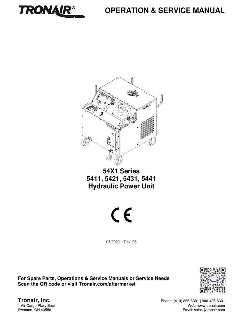
Tronair 5731 Operation manual

1740 Eber Rd Tronair, Inc. Phone: (419) 866-6301
Holland, OH 43528-9794 www.tronair.com 800-426-6301
Operation & Service Instructions
Model: 5731
Hydraulic Power Unit
08/2016 Rev. 08

REVISION DATE TEXT AFFECTED
010 03/2004 Major revision
02 05/2004 Modified part numbers
03 06/2006 Modified 9.3.2
Modified 9.7.1 Electric Panel Parts List
Modified 9.10 Item 19
04 06/2008 Modified 12.2.1 Self Calibration
05 10/2009 Modified 9.10 Electrical Components
Added 9.10.1 Electrical Components With 100 ft Input Cord Option
06 06/2010 Modified illustration for 5.3.5 Hydraulic Pump Controls and
9.2 Electric Motor, modified 9.3.1 Hydraulic Pump Replacement Parts
07 04/2011 Modified 9.6 Hydraulic Hoses Parts List
08 08/2016 Added 9.13.6 Hand Pump High Displacement

Model: 5731
Hydraulic Power Unit
08/2016 | Rev. 08
TABLE OF CONTENTS PAGE
1.0 PRODUCT INFORMATION...........................................................................................................................................1
1.1 DESCRIPTION...........................................................................................................................................................1
1.2 MODEL & SERIAL NUMBER.....................................................................................................................................1
1.3 MANUFACTURER.....................................................................................................................................................1
1.4 FUNCTION.................................................................................................................................................................1
1.5 REQUIREMENTS ......................................................................................................................................................1
2.0 SAFETY INFORMATION...............................................................................................................................................1
2.1 USAGE AND SAFETY INFORMATION.....................................................................................................................1
2.2 EXPLANATION OF WARNING & DANGER SIGNS..................................................................................................1
2.3 COMPONENT SAFETY FEATURES.........................................................................................................................1
2.4 FUNCTIONAL SAFETY FEATURES .........................................................................................................................2
2.5 PERSONAL PROTECTION EQUIPMENT.................................................................................................................2
2.6 SAFETY GUIDELINES...............................................................................................................................................2
2.7 GENERAL COMMENT...............................................................................................................................................2
3.0 PREPARATION PRIOR TO FIRST USE.......................................................................................................................2
3.1 GENERAL..................................................................................................................................................................2
3.2 SERVICING RESERVOIR .........................................................................................................................................2
3.3 CONNECTING ELECTRICAL LEADS .......................................................................................................................2
4.0 TRAINING......................................................................................................................................................................2
4.1 TRAINING REQUIREMENTS ....................................................................................................................................2
4.2 TRAINING PROGRAM...............................................................................................................................................2
4.3 OPERATOR TRAINING.............................................................................................................................................2
5.0 OPERATION..................................................................................................................................................................3
5.1 OPERATING PARAMETERS ....................................................................................................................................3
5.2 NUMERICAL VALUES...............................................................................................................................................3
5.2.1 Model .........................................................................................................................................................................3
5.2.2 Physical......................................................................................................................................................................3
5.2.3 Hydraulic Pump..........................................................................................................................................................3
5.2.4 Electric Motor.............................................................................................................................................................4
5.2.5 Filters .........................................................................................................................................................................4
5.2.6 Hand Pump (Option M) ..............................................................................................................................................4
5.3 LOCATION & LAYOUT OF CONTROLS ...................................................................................................................5
5.3.1 Front Panel Controls ..................................................................................................................................................5
5.3.2 Electrical Control Panel..............................................................................................................................................6
5.3.3 Hydraulic Control Panel..............................................................................................................................................7
5.3.4 Rear Panel Controls...................................................................................................................................................8
5.3.5 Hydraulic Pump Controls............................................................................................................................................9
5.3.6 Hand Pump Controls (Option M)..............................................................................................................................10
5.3.7 Dual System Controls (Option C).............................................................................................................................11
5.4 START UP PROCEDURES .....................................................................................................................................12
5.4.1 Procedure for First Time or Different Electrical Supply ONLY..................................................................................12
5.4.2 Initial Start Up of the HPU........................................................................................................................................12
5.5 PRELIMINARY ADJUSTMENTS FOR OPERATION...............................................................................................12
5.5.1 Flow Control Adjustment..........................................................................................................................................12
5.5.2 Pressure Control Adjustment ...................................................................................................................................13
5.5.3 Reservoir Selector Valve Operation.........................................................................................................................13
5.5.4 Bypass Valve Operation...........................................................................................................................................13
5.6 BLEEDING AIR FROM SYSTEM.............................................................................................................................14
5.6.1 To Easily Purge the Unit of Air.................................................................................................................................14
5.7 DUAL SYSTEM OPERATION (Option C) ................................................................................................................14
5.7.1 To Operate the Dual System....................................................................................................................................14
5.8 HAND PUMP OPERATION (Option M)....................................................................................................................14
5.8.1 To Operate the Hand Pump.....................................................................................................................................14
5.9 SAMPLE VALVE......................................................................................................................................................15
5.10 EMERGENCY SHUT DOWN PROCEDURE ...........................................................................................................15
5.11 DESCRIPTION OF ALARM SYSTEMS ...................................................................................................................15
5.11.1 High Fluid Temperature Indicator.............................................................................................................................15
5.11.2 Voltage/Phase Monitor Indicator (Options H
J) .....................................................................................................15
5.11.3 High and Low Reservoir Level Indicator (Option L)..................................................................................................15
5.11.4 Clogged Filter Indicator Light ...................................................................................................................................15
6.0 PACKAGING AND STORAGE....................................................................................................................................16
6.1PACKAGING REQUIREMENTS..............................................................................................................................16
6.2 HANDLING...............................................................................................................................................................16
6.3 PACKAGING PROTECTION ...................................................................................................................................16

Model: 5731
Hydraulic Power Unit
08/2016 | Rev. 08
6.4 LABELING OF PACKAGING ...................................................................................................................................16
6.5 STORAGE COMPATIBILITY ...................................................................................................................................16
6.6 STORAGE ENVIRONMENT....................................................................................................................................16
6.7 STORAGE SPACE AND HANDLING FACILITIES...................................................................................................16
7.0 TRANSPORTATION ...................................................................................................................................................16
8.0 TROUBLE SHOOTING................................................................................................................................................17
8.1 HPU WILL NOT START...........................................................................................................................................17
8.2 NO FLOW ................................................................................................................................................................17
8.3 REDUCED FLOW....................................................................................................................................................18
8.4 NO PRESSURE or REDUCED PRESSURE............................................................................................................18
8.5 FLUID OVERHEATS................................................................................................................................................18
8.6 HAND PUMP (Option M) IS NOT PUMPING FLUID................................................................................................18
9.0 MAINTENANCE ..........................................................................................................................................................19
9.1 GENERAL................................................................................................................................................................19
9.2 ELECTRIC MOTOR.................................................................................................................................................19
9.3 HYDRAULIC PUMP.................................................................................................................................................20
9.3.1 Hydraulic Pump Replacement Parts.........................................................................................................................20
9.3.2 Hydraulic Pump Replacement Seal Kits...................................................................................................................20
9.4 HYDRAULIC FLUID.................................................................................................................................................21
9.5 FILTERS ..................................................................................................................................................................21
9.5.1 Pressure Filter Element............................................................................................................................................22
9.5.2 Return Filter Element ...............................................................................................................................................23
9.5.3 Hand Pump (Option M) Filter Element .....................................................................................................................24
9.5.4 Desiccant Air Filter...................................................................................................................................................25
9.5.5 Pressure Filter Assembly with Electric Filter Clogging Indicator...............................................................................26
9.5.6 Return Filter Assembly.............................................................................................................................................27
9.6 HYDRAULIC HOSES...............................................................................................................................................28
9.7 INSTRUMENT PANEL.............................................................................................................................................29
9.7.1 Electric Panel...........................................................................................................................................................30
9.7.2 Hydraulic Panel........................................................................................................................................................31
9.7.3 Pressure Manifold Assembly....................................................................................................................................32
9.7.3.a System Pressure Relief Valve..................................................................................................................................33
9.7.3.b Check Valve.............................................................................................................................................................34
9.7.3.c Bypass Valve ...........................................................................................................................................................34
9.8 RESERVOIR ASSEMBLY........................................................................................................................................35
9.9 RETURN MANIFOLD ASSEMBLY...........................................................................................................................37
9.9.1 Return System Pressure Relief Valve......................................................................................................................38
9.10 ELECTRICAL COMPONENTS ................................................................................................................................39
9.10.1 Electrical Components With 100 ft Input Cord option...............................................................................................41
9.11 HEAT EXCHANGER ASSEMBLY............................................................................................................................44
9.12 EXTERNAL COMPONENTS....................................................................................................................................45
9.13 ADDITIONAL FEATURES........................................................................................................................................46
9.13.1 50 ft (15.2 m) Hoses (Option B) ...............................................................................................................................46
9.13.2 Dual System (Option C) ...........................................................................................................................................46
9.13.3 Voltage/Phase Monitor (Options H
J)....................................................................................................................47
9.13.4 Electric Reservoir Level (Option L)...........................................................................................................................48
9.13.5 Hand Pump (Option M) ............................................................................................................................................49
9.13.5.a Two Stage Pump with Relief....................................................................................................................................51
9.13.6 Hand Pump High Displacement (Option 7) ..............................................................................................................53
9.13.7 Towing Trailer (Option N).........................................................................................................................................55
9.14 REPLACEMENT LABELS PARTS LISTS................................................................................................................56
9.14.1 Base Unit..................................................................................................................................................................56
9.14.2 Fluid Labels..............................................................................................................................................................56
9.14.3 Filter Element Kit Labels ..........................................................................................................................................56
9.14.4 Dual System (Option C) ...........................................................................................................................................56
9.14.5 Hand Pump (Option M) Labels.................................................................................................................................56
10.0 PROVISION OF SPARES ...........................................................................................................................................57
10.1 SOURCE OF SPARE PARTS..................................................................................................................................57
10.2 RECOMMENDED SPARE PARTS LISTS ...............................................................................................................57
10.2.1 Spare Electrical Parts...............................................................................................................................................57
10.2.2 Spare Parts..............................................................................................................................................................57
11.0 ELECTRICAL POWER REQUIREMENTS..................................................................................................................57
12.0 CALIBRATION OF INSTRUMENTATION...................................................................................................................58
12.1 SOURCE OF CALIBRATION...................................................................................................................................58
12.2 ANALOG PRESSURE GAUGE System Pressure.................................................................................................58
12.2.1 Self Calibration.........................................................................................................................................................58
12.3 ANALOG PRESSURE GAUGE (Hand Pump Pressure- Option M Only )................................................................59
12.3.1 Self Calibration.........................................................................................................................................................59
Model: 5731
Hydraulic Power Unit
08/2016 | Rev. 08
12.4 ANALOG TEMPERATURE GAUGE (Pyrometer).....................................................................................................59
12.4.1 Self Calibration.........................................................................................................................................................59
13.0 IN SERVICE SUPPORT ..............................................................................................................................................60
14.0 GUARANTEES/LIMITATION OF LIABILITY ..............................................................................................................60
15.0 APPENDICES..............................................................................................................................................................60

Model: 5731
Hydraulic Power Unit
08/2016 | Rev. 08 Page | 1
This product can not be modified without the written approval of Tronair, Inc. Any modifications done without written approval
voids all warranties and releases Tronair, Inc., it suppliers, distributors, employees, or financial institutions from any liability
from consequences that may occur. Only Tronair OEM replacement parts shall be used.
1.0 PRODUCT INFORMATION
1.1 DESCRIPTION
Hydraulic Power Unit
Model Number: Fluid Type:
5731 Aviation Phosphate Ester, Type IV
1.2 MODEL & SERIAL NUMBER
Reference nameplate on unit.
1.3 MANUFACTURER
TRONAIR, Inc. Telephone: (419) 866-6301 or 800-426-6301
1740 Eber Road Fax: (419) 867-0634
Website: www.tronair.com
1.4 FUNCTION
The Hydraulic Power Unit (HPU) provides a source of clean, pressurized hydraulic fluid for performing required aircraft
maintenance. An electric motor drives a pressure compensated piston pump. Filters are provided on the pressure and return
systems. A bypass (dump) valve allows starting and stopping of the unit under a no-load, safe condition. The unit may use
either the aircraft or on-board HPU reservoir. Cooling is provided for continuous operation.
1.5 REQUIREMENTS
Adequate electrical power must be provided for proper functioning of the HPU. See the unit nameplate for proper voltage and
frequency. See the Technical Manual for proper sizing of electrical supply and protection equipment in the facility.
2.0 SAFETY INFORMATION
2.1 USAGE AND SAFETY INFORMATION
The HPU provides pressurized hydraulic fluid for performing aircraft maintenance.
To insure safe operations please read the following statements and understand their meaning. Also refer to your equipment
manufacturer’s manual for other important safety information. This manual contains safety precautions which are explained
below. Please read carefully.
WARNING! —Warning is used to indicate the presence of a hazard that can cause severe personal injury,
death, or substantial property damage if the warning notice is ignored.
CAUTION! —Caution is used to indicate the presence of a hazard that will or can cause minor personal injury
or property damage if the caution notice is ignored.
2.2 EXPLANATION OF WARNING & DANGER SIGNS
Accidental Starts! Before servicing the HPU or equipment, always disconnect electrical power supply to prevent
accidental starting.
Rotating Parts! Keep hands, feet, hair, and clothing away from all moving parts to prevent injury. Never operate
the HPU with covers, shrouds, or guards removed.
Electrical Shock! Never touch electrical wires or components while the HPU is attached to the power source.
They can be sources of electrical shock. DO NOT operate HPU with cabinet panels removed.
Pressurized Fluid! Before servicing the HPU or equipment, always open the bypass valve to relieve any residual
pressure in the hydraulic system.
2.3 COMPONENT SAFETY FEATURES
Pump/Motor coupling guard Control circuit fuses
Sheet metal panels Motor overload protection
Pressure and return system relief valves

Model: 5731
Hydraulic Power Unit
08/2016 | Rev. 08 Page | 2
2.0 SAFETY INFORMATION (continued)
2.4 FUNCTIONAL SAFETY FEATURES
Emergency shut off switch Calibration port shut off valve
Floor lock Fluid sample shut off valve
2.5 PERSONAL PROTECTION EQUIPMENT
Safety glasses must be worn when operating the HPU.
Additional equipment recommended by the fluid manufacturer (gloves, etc.). Reference Appendix VII Material Safety
Data Sheet pertaining to fluid(s).
2.6 SAFETY GUIDELINES
Operator must be properly trained prior to operating the HPU.
HPU power switch must be in "Off" position when connecting or disconnecting hoses to the aircraft.
Bypass valve must be in the "Open" position when starting or stopping the HPU.
Electrical power must be disconnected from the HPU and the bypass valve must be in the "Open" position before
servicing the HPU. (Reference Technical Manual for details on servicing the HPU.)
2.7 GENERAL COMMENT
The HPU is intended to be operated by personnel trained in the proper use in conjunction with the aircraft maintenance
manual.
The HPU must be used in accordance with the Technical and Operator Manuals and the intended aircraft.
3.0 PREPARATION PRIOR TO FIRST USE
3.1 GENERAL
Prior to operating the HPU, the user should become familiar with this Operator Manual.
3.2 SERVICING RESERVOIR
Fill the reservoir with the correct fluid (see label next to reservoir fill for correct type of fluid) until fluid level is above the
minimum fluid level mark but below the maximum fluid level. See Figure 5.3.1 Front Panel Controls for reservoir fill location.
3.3 CONNECTING ELECTRICAL LEADS
Electrical Shock! Never touch electrical wires or components while electrical power is attached. Only qualified
electricians should connect the electrical leads.
Install plug onto the electrical cord. If motor rotation is not correct, change any two of the three leads at the plug.
Reference 11.0 Electrical Power and Protection Requirements for power requirements and fuse sizes.(See 5.4
Start up Procedures before starting HPU.)
WARNING!
Balanced three phase voltage must be available to prevent overheating and damage to the motor.
Voltage unbalanced between phases occurs when the voltages differ from one another.
Some reasons for imbalance are:
1. Unequal loading of each phase
2. Poor connections in the supply
3. Single phase condition caused by blown fuses or bad connections
If these conditions occur in the incoming power system, a protective devise, such as a voltage monitor,
should be installed on the machine to prevent motor damage.
4.0 TRAINING
4.1 TRAINING REQUIREMENTS
The employer of the operator is responsible for providing a training program sufficient for the safe operation of the HPU.
4.2 TRAINING PROGRAM
The employer provided operator training program should cover safety procedures concerning use of the HPU in and around
the intended aircraft at the intended aircraft servicing location.
4.3 OPERATOR TRAINING
The operator training should provide the required training for safe operation of the HPU.
NOTE: Maintenance and Trouble Shooting are to be performed by a skilled and trained technician.

Model: 5731
Hydraulic Power Unit
08/2016 | Rev. 08 Page | 3
5.0 OPERATION
5.1 OPERATING PARAMETERS
The user shall use the HPU in accordance with the aircraft manufacturer's instructions.
The user shall operate the HPU in accordance with the Technical and Operator Manuals.
The employer of the operator shall provide all necessary training.
5.2 NUMERICAL VALUES
5.2.1 Model
5731
Fluid Type:Aviation Phosphate Ester, Type IV
5.2.2 Physical
Weight (Dry): 3,500 lbs (1,588 kg)
Dimensions:Width 63.75 in (162 cm) Add 7.5 in (19 cm) for Dual System
Height 59 in (149.9 cm)
Depth 78 in (198 cm)
Power Cord: 50 ft (15.24 m) long
Pressure Hoses: 25 ft (7.62 m).....................Standard Length
50 ft (15.24 m)...................Optional Length
-16 (1 in, 25.4 mm)............Working Diameter
Return Hoses: 25 ft (7.62 m).....................Standard Length
50 ft (15.24 m)...................Optional Length
-24 (1½ in, 38.1 mm).........Working Diameter
Hand Pump Hose: 15 ft (4.57 m).....................Standard Length
-6 (3/8 in, 9.53 mm)...........Working Diameter
5.2.3 Hydraulic Pump
A pressure compensated, adjustable maximum volume piston pump.
Maximum flow at 60 Hz..................................................................... 34 gpm (129 lpm)
Maximum flow at 50 Hz..................................................................... 28 gpm (107 lpm)
Maximum operating pressure at 50 Hz and 60 Hz............................ 3,500 psi (241 bar)
System pressure relief valve setting.................................................. 3,750 psi (259 bar)
Performance Curve for 50 Hz and 60 Hz .......................................... Reference Figure 5.2.3
FIGURE 5.2.3 Performance Curve (50 Hz and 60 Hz)
0
500
1000
1500
2000
2500
3000
3500
4000
0.0 4.0 8.0 12.0 16.0 20.0 24.0 28.0 32.0 36.0
FLOW (GPM)
PRESSURE (PSI)
0
46
92
138
184
230
276
0.0 17.0 34.0 51.0 68.0 85.0 102.0 119.0 136.0
FLOW (LPM)
PRESSURE (BAR)
OPERATING RANGE
50Hz
60Hz
PERFORMANCE CURVE-57 SERIES HYDRAULIC POWER UNIT

Model: 5731
Hydraulic Power Unit
08/2016 | Rev. 08 Page | 4
5.2 NUMERICAL VALUES (continued)
5.2.4 Electric Motor
A 75 horsepower, TEFC electric motor is the prime mover for the HPU. This is attached to the hydraulic pump using a
pump/motor adapter and a spider/coupling rotating interface.
MOTOR POWER REQUIREMENTS
60 Hz Applications
50 Hz Applications
Voltage
Full Load Amps
Voltage
Full Load Amps
380
103.8
380
107
460
92
415
105
575
73.6
440
92
FIGURE 5.2.4 - Motor Power Requirements
5.2.5 Filters
Pressure.......................................... 2 micron rating, non-bypass high collapse microglass type. Non-cleanable element.
Return............................................. 5 micron rating, 25 psi (1.72 bar) bypass microglass type. Non-cleanable element.
Hand Pump (Option M)................... 2 micron rating, non-bypass microglass type. Non-cleanable element.
Air/Desiccant................................... 3 micron filter, silica gel desiccant type. Non-cleanable element.
5.2.6 Hand Pump (Option M)
Two stage hand pump, low pressure stage 0500 psi (034.47 bars) and 5005,000 psi (34.47344.74 bars) high pressure
stage. Pump automatically changes stage internally based on system pressure.
Low Pressure Stage: Piston Diameter........................1½ in (38.1 mm)
Working Pressure.....................0500 psi (034.47 bar)
Displacement/Stroke................2.1 in3 (34.4 cm3)
Force/100 psi (6.89 bar)...........12.0 lbs/100 psi (7.74 N/bar)
High Pressure Stage: Piston Diameter........................5/8 in (15.88 mm)
Working Pressure.....................5005,000 psi (34.47344.74)
Displacement/Stroke................0.4 in3 (6.55 cm3)
Force/100 psi (6.89 bar)...........2.2 lbs/100 psi (1.42 N/bar)
Pressure Relief Setting: 5,250 psi (362.0 bar)
5.0 Operation continued on following page
FIGURE 5.2.4 Motor Power Requirements

Model: 5731
Hydraulic Power Unit
08/2016 | Rev. 08 Page | 5
5.0 OPERATION (continued)
5.3 LOCATION & LAYOUT OF CONTROLS
5.3.1 Front Panel Controls
Electrical Control Panel.......................... See Section 5.3.2
Hydraulic Control Panel ......................... See Section 5.3.3
Bypass Valve ......................................... For loading and unloading the Hydraulic Pump.
Flowmeter .............................................. Displays the flow from the Hydraulic Pump.
Pump Control Access............................. See Figure 5.3.5 - Hydraulic Pump Controls.
Reservoir Selector.................................. For selecting between using the aircraft reservoir or the HPU reservoir.
Sight Gauge........................................... Visual indicator displays the fluid level in the reservoir.
Reservoir Fill Access.............................. Locking cap for servicing the HPU reservoir.
Desiccant Filter ...................................... Access to the reservoir air filter/desiccant filter.
Hand Pump (Option M).......................... Access for hand pump and relief screw, handle stored inside.
Locking Swivel Caster............................ Locking/unlocking, foot actuated and released locking front caster.
Running Light......................................... Displays green LED light when unit is running.
FIGURE 5.3.1 Front Panel Controls

Model: 5731
Hydraulic Power Unit
08/2016 | Rev. 08 Page | 6
5.3 LOCATION & LAYOUT OF CONTROLS (continued)
5.3.2 Electrical Control Panel
Emergency Stop..................................... Removes power to all electrical devices, must turn to reset.
Stop Switch............................................ Turns off the electric motors driving the hydraulic pump and cooling fan.
Start Switch............................................ Turns on the electric motors driving the hydraulic pump and cooling fan.
HPU Power "On" Indicator Light............. Light is illuminated when the electric motors driving the hydraulic pump and
cooling fan are on.
High Fluid Temperature ......................... Light is illuminated when the return fluid temperature reaches 160F (71C) or
Indicator Light above. The HPU will shut down when light is illuminated. The HPU can be re-
started when the fluid has cooled and the indicator light is off.
High Reservoir Fluid Level..................... Light is illuminated when the fluid level in the reservoir is above the normal
Indicator Light (Option L) operating range. The HPU will shut down until the fluid level is restored to a
normal operating level.
Low Reservoir Fluid Level...................... Light is illuminated when the fluid level in the reservoir is below the normal
Indicator Light (Option L) operating range. The HPU will shut down until the fluid level is restored to a
normal operating level.
Voltage/Phase Monitor........................... Light is illuminated if any of the following conditions occur
Indicator Light (Options H
J) Voltage imbalance between L1, L2, L3, greater than 5%
Loss of voltage from L1, L2, L3
Over voltage from L1, L2, L3, greater than 5%
Change in phase orientation between L1, L2, L3. The HPU will shut down
until the electrical problem is corrected.
Clogged Pressure Filter Indicator........... Light is illuminated when the pressure filter element requires changing. The HPU
will not shut down when illuminated. Pressing the illuminated button will reset the
light.
5.3 Location & Layout of Controls continued on following page.
FIGURE 5.3.2 Electrical Control Panel

Model: 5731
Hydraulic Power Unit
08/2016 | Rev. 08 Page | 7
5.3 LOCATION & LAYOUT OF CONTROLS (continued)
5.3.3 Hydraulic Control Panel
System Pressure Gauge........................ Displays the system pressure on an analog fluid dampened gauge.
Pyrometer .............................................. Displays the fluid temperature in the return system on an analog gauge. A
warning indicator preset to 160F (71C) warns of high operating temperature.
Pressure Gauge Calibration Port ........... Allows for calibration of the system pressure gauge up to the operating pressure
of HPU. Calibration port shut off valve must be used in conjunction with the
calibration port.
Calibration Port Shut Off Valve .............. Used to shut off pressure to the calibration port. This valve should only be
opened when the external standard gage is attached.
(See Technical Manual for proper procedure.)
Hand Pump Pressure Gauge................. Displays the hand pump system pressure on an analog fluid dampened gauge.
(Option M)
FIGURE 5.3.3 Hydraulic Control Panel

Model: 5731
Hydraulic Power Unit
08/2016 | Rev. 08 Page | 8
5.3 LOCATION & LAYOUT OF CONTROLS (continued)
5.3.4 Rear Panel Controls
* Fluid Pressure System........................ The source of pressurized fluid from the HPU that flows to the aircraft pressure
system through the pressure hose.
* Fluid Return System........................... Fluid returning to the HPU from the aircraft that flows through the return hoses.
Pressure Fluid Filter............................... Filters the pressurized fluid before it flows to the aircraft pressure system.
Return Fluid Filter................................... Filters the fluid returning from the aircraft before it enters the HPU.
Pressurized Fluid Sample Port............... A sample valve is provided to obtain a fluid sample for analysis. In order to obtain
a representative sample, it is suggested that ANSI/B93.19M-1972 (R1993) be
followed.
Hand Pump Pressure Filter:................... Filters the pressurized fluid before it flows to the aircraft system.
(Option M)
Hose Racks............................................ Location for storing the pressure, return and optional hand pump hoses when not
in use.
Power Cord Hanger ............................... Location for storing the power cord when not in use.
Dual System (Optional) consists of two (2) each of these items.
5.3 Location & Layout of Controls continued on following page.
FIGURE 5.3.4 Rear Panel Controls

Model: 5731
Hydraulic Power Unit
08/2016 | Rev. 08 Page | 9
5.3 LOCATION & LAYOUT OF CONTROLS (continued)
5.3.5 Hydraulic Pump Controls
The hydraulic pump flow control and pressure control are located through the pump control access door.
FIGURE 5.3.5 Hydraulic Pump Controls
Flow Control........................................... This control is used to set the maximum flow required from the HPU.
Pressure Control.................................... The pressure control is used to set the system pressure of the HPU during
operation.

Model: 5731
Hydraulic Power Unit
08/2016 | Rev. 08 Page | 10
5.3 LOCATION & LAYOUT OF CONTROLS (continued)
5.3.6 Hand Pump Controls (Option M)
Reference 5.8 Hand Pump Operation
Pump Handle ......................................... Located inside the front access door is the hand pump handle used for opening
and closing the hand pump relief screw and stroking the hand pump arm.
Hand Pump Relief Screw....................... Accessed through the front panel opening, this screw allows opening and closing
of the hand pump hydraulic circuit using the hand pump handle.
Hand Pump Arm..................................... The handle is used to access the hand pump arm used for up and down motion
to produce hydraulic flow and pressure.
5.3 Location & Layout of Controls continued on following page.
FIGURE 5.3.6 Hand Pump Controls

Model: 5731
Hydraulic Power Unit
08/2016 | Rev. 08 Page | 11
5.3 LOCATION & LAYOUT OF CONTROLS (continued)
5.3.7 Dual System Controls (Option C)
Reference 5.7 Dual System Operation.
Pressure Manifold.................................. Houses the pressure valves.
Fluid Pressure Ball Valve....................... Used to turn on and off the flow to separate aircraft systems. Always use in either
fully open or fully closed position; never use in a partially open position.
Fluid Pressure Hose............................... Connects HPU to aircraft pressure systems.
Fluid Return Hose.................................. Connects HPU to aircraft return systems.
WARNING!
NEVER open or close dual system valves without shutting off the Hydraulic Power Unit. Damage to the
aircraft system or reservoir may result if either return line valve is closed while the machine is running.
Fluid Return Ball Valve........................... Used to turn on and off the flow from separate aircraft systems. Always use in
either fully open or fully closed position; never use in a partially open position.
FIGURE 5.3.7 Dual System Controls

Model: 5731
Hydraulic Power Unit
08/2016 | Rev. 08 Page | 12
FIGURE 5.4.1
Pump/Motor Coupling Access
5.0 OPERATION (continued)
5.4 START UP PROCEDURES
5.4.1 Procedure for First Time or Different Electrical Supply ONLY
Phase Monitor (Options H
J Only): Check that the phase monitor light on the
instrument panel is not illuminated. If the light is illuminated, change any two of the three
input leads at the plug. Once the phase monitor light is not illuminated with power
attached, check for proper motor rotation.
a. Remove the pump/motor coupling guard. Reference
Figure 5.4.1
Pump/Motor Coupling Access.
Rotating Parts! Keep hands, feet, hair, and clothing away from all
moving parts to prevent injury. Never operate the HPU with covers,
shrouds, or guards removed.
Electrical Shock! Never touch electrical wires or components while
the HPU is attached to the power source. They can be sources of
electrical shock.
Do not operate HPU with cabinet panels removed.
b. Verify that the unit has been prepared for use by connecting electrical leads and servicing the reservoir. (Reference
section 3.0 Preparation Prior to First Use.)
c. Keeping hands clear of the pump/motor coupling area, momentarily press the start button and immediately press the stop
button.
d. Observe direction of rotation of the pump/motor coupling. When the Operator is facing the front panel, the pump/motor
coupling should be rotating in a clockwise direction.
e. If the pump/motor coupling is rotating in a counter-clockwise direction, change any two of the three leads at the plug.
Observe direction of rotation to verify that pump/motor is rotating in a clockwise direction.
f. Replace the pump/motor coupling guard.
5.4.2 Initial Start Up of the HPU
a. Unit must be prepared per section 3.0 Preparation Prior to First Use and section 5.4.1 First Time or Different Electrical
Supply ONLY before starting the HPU.
b. Operator must be familiar with this manual and be properly trained prior to starting the HPU.
c. Connect quick disconnects to hose ends or cap the pressure and return hose ends.
d. Place the reservoir selector valve in "HPU Reservoir" position.
e. Place the bypass valve in the "Open" position.
f. Press the start switch and adjust the flow control until approximately 10 gpm (38 lpm) is displayed on the flowmeter. (If no
flow displays on the flowmeter after adjusting the flow control, reference Trouble Shooting 8.2 No Flow).
g. Close the bypass valve, adjust the pressure control until 3,000 psi (206.84 bar) is displayed on the pressure gauge. (If no
pressure displays on the system pressure gauge after adjusting the pressure control, reference Trouble Shooting 8.4 No
Pressure or Reduced Pressure).
h. Open the bypass valve; press the stop switch.
NOTE: Maintenance and Trouble Shooting are to be performed by a skilled and trained technician.
5.5 PRELIMINARY ADJUSTMENTS FOR OPERATION
The following are basic to the operation of the HPU and should be thoroughly understood. The pressure and flow controls
have lock nuts to prevent rotation of the control shaft during operation. These nuts should be moved away from the pump
during adjustment of flow or pressure in order to eliminate binding of the control shafts.
5.5.1 Flow Control Adjustment
a. Open bypass valve.
b. Select "Hydraulic Power Unit" position with reservoir selector valve.
c. Start HPU.
d. Adjust flow control on pump for maximum desired flow. Observing the flowmeter, read flow in gallons (liters) per minute
directly from flowmeter. Be sure the control shaft lock nut is loose during adjustment. Tighten after adjustment to maintain
setting.
5.5 Preliminary adjustments for operation continued on following page.

Model: 5731
Hydraulic Power Unit
08/2016 | Rev. 08 Page | 13
5.5 PRELIMINARY ADJUSTMENTS FOR OPERATION (continued)
5.5.2 Pressure Control Adjustment
a. Open bypass valve.
b. Select "Hydraulic Power Unit" position with reservoir selector valve.
c. Start HPU.
d. Close bypass valve.
e. Adjust pressure control for desired pressure; observing the system pressure gauge, read in psi (bars). Be sure the control
shaft lock nut is loose during adjustment. Tighten after adjustment to maintain setting.
NOTE: Once the flow and pressure controls have been adjusted, it is not necessary to change these settings after
each operation unless desired.
5.5.3 Reservoir Selector Valve Operation
Operation of the reservoir selector valve allows the operator to select either the aircraft reservoir (closed loop) or the HPU
reservoir (open loop).
CAUTION!
The reservoir selector valve should only be operated when the HPU is not running. The operation of the
reservoir selector valve should be done prior to starting the HPU.
a. Aircraft Reservoir Position (Closed Loop)
In this position, the HPU is dependent on the aircraft reservoir and system for an adequate supply of fluid. Cavitation, due to
an inadequate fluid supply from the aircraft, may be indicated by erratic fluctuation of the system pressure gauge or flowmeter.
At times, the aircraft fluid supply will be restricted due to small return oil lines in the aircraft. If this is a problem, decrease the
flow control setting until the cavitation is eliminated.
b. HPU Reservoir Position (Open Loop)
In this position, the HPU reservoir supplies fluid to the pump and accepts return fluid from the aircraft. It is desirable to operate
the HPU in this mode since it eliminates any possibility of cavitation.
Since the HPU reservoir is vented to atmosphere and the aircraft is at a higher level, it is normal for the aircraft reservoir to
drain into the HPU reservoir. It is, therefore, necessary to be sure that sufficient room is available in the HPU reservoir to
accommodate the additional fluid.
CAUTION!
The aircraft system reservoir must be serviced after completion of operational testing.
In the "HPU Reservoir" position, faster landing gear swings are usually possible since there is no restriction to flow at the
pump inlet.
5.5.4 Bypass Valve Operation
The bypass valve is used for unloading the pump. The valve should be either in the fully open or fully closed position only. Do
not operate the valve in a partially open position.
a. Start Up Operation
The bypass valve must be opened prior to starting the HPU in order to allow the motor to start under a no load condition and
not pressurize the aircraft hydraulic system.
b. Shut Down Operation
Prior to shutdown, the bypass valve must be opened to bleed off any residual system pressure.
CAUTION!
Excessive heat, which could damage machine components, will be generated if the bypass valve is
partially open or is used for regulating flow or pressure.
Use the flow and pressure controls for regulation.
Use the bypass valve for unloading the system only.

Model: 5731
Hydraulic Power Unit
08/2016 | Rev. 08 Page | 14
5.0 OPERATION (continued)
5.6 BLEEDING AIR FROM SYSTEM
Rapid fluctuations of the pressure gage and flow-meter are indications of cavitation or entrapped air in the hydraulic lines
and/or components. Air may enter the system when:
Operating the unit with insufficient oil in the reservoir.
Changing a component on the aircraft.
Changing hose connections and/or couplings.
5.6.1 To Easily Purge the Unit of Air
a. Fill reservoir to recommended level.
b. Open bypass valve.
c. Place reservoir selector valve in “Hydraulic Power Unit” position.
d. Start unit and adjust flow control to maximum position.
NOTE: If fluid is not flowing, shut off HPU and reference 8.2 No Flow in Trouble Shooting section of Technical
Manual
e. Run unit for five (5) minutes and shut off.
f. If additional bleeding is required, connect the pressure and return hoses together and open all pressure and return ball
valves at the rear of the HPU. Start the HPU and slowly close the bypass valve (system pressure should remain under
200 psi (approximately 14 bars). Allow fluid to flow at full flow for five (5) minutes, then shut the HPU off.
WARNING!
Failure to open the return ball valves will cause hose or valve rupture. Property damage and personal
injury can result.
5.7 DUAL SYSTEM OPERATION (Option C)
The dual system option allows control of fluid flow to aircraft with two hydraulic systems. The systems consist of two sets of
hoses and valves located in the pressure and return systems. The valves are mounted on the rear of the hydraulic power unit
and are of the 90oball type. The valves are open when the operating handle is in line with the valve.
Although both systems may be operated simultaneously, usually only one system is required at any one time. If both valve
sets are open simultaneously, the pump output will be divided between the two systems. Also, cross flow between aircraft
reservoirs may occur if a reservoir level or pressure differential exists. Select valve positions prior to starting machine.
5.7.1 To Operate the Dual System
a. Before starting machine, open pressure and return valves of the same system.
WARNING!
Ensure pressure and return hoses of the same system are paired and used together.
b. After completing tests on one system, shut the machine off before selecting the second system.
WARNING!
NEVER open or close dual system valves without shutting off the Hydraulic Power Unit. Damage to the
aircraft system or reservoir may result if either return line valve is closed while the machine is running.
5.8 HAND PUMP OPERATION (Option M)
The Hand Pump Option allows for filling the reservoir (low pressure) or static testing of components or system (high pressure).
The hand pump circuit is separate from the main hydraulic system; a separate filter and hose are attached to the back panel of
the HPU.
5.8.1 To Operate the Hand Pump
a. Remove the pump handle from inside the front access door. (Reference Figure 5.3.6
Hand Pump Controls)
b. Insert the end of the pump handle through the front panel opening into the hand pump relief screw.
c. Turn the pump handle clockwise to close the relief screw.
d. Insert the pump handle onto the hand pump arm through the front panel slot.
e. Pump the handle using an up and down motion. Observe the hand pump system pressure on the hydraulic control panel
(Figure 5.3.3 Hydraulic Control Panel). The pump is an automatic two stage pump. 500 psi (34.47 bar) can be produced
with high fluid flow and 5,000 psi (344.74 bars) can be produced with low fluid flow.
f. Turning the relief screw in a counter-clockwise direction releases hydraulic pressure in the hand pump system.
Pressurized Fluid! Before disconnecting the hand pump pressure hose, ALWAYS open the relief screw valve to
relieve any residual pressure in the hydraulic system.
5.0 Operation continued on following page.

Model: 5731
Hydraulic Power Unit
08/2016 | Rev. 08 Page | 15
5.0 OPERATION (continued)
5.9 SAMPLE VALVE
A sample valve is provided on the rear of the unit to obtain a fluid sample for analysis or inspection.
In order to obtain a representative fluid sample, it is suggested that ANSI/B93.19M-1972 (R1993) be followed. Reference
Appendix VIII.
Pressurized Fluid! Before servicing the HPU or equipment, ALWAYS open the bypass valve to relieve any
residual pressure in the hydraulic system.
5.10 EMERGENCY SHUT DOWN PROCEDURE
In the event an emergency shutdown is necessary, press the emergency stop switch located on the electrical panel.
(Reference Figure 5.3.2
Electrical Control Panel) Open the bypass valve to remove any system pressure.
5.11 DESCRIPTION OF ALARM SYSTEMS
Reference Figure 5.3.2 Electrical Control Panel.
5.11.1 High Fluid Temperature Indicator
The indicator light for high fluid temperature is an active light which will illuminate when the return fluid temperature is 160F
(71C) or above. The HPU will shut down if the light is illuminated. The HPU can be re-started when the fluid has cooled
sufficiently and the light has shut off.
If the high temperature light is illuminated reference section 8.0 Trouble Shooting.
5.11.2 Voltage/Phase Monitor Indicator (Options H
J)
The indicator light for the voltage/phase monitor is an active light which will illuminate if there is a problem with the incoming
electrical power source. The HPU will shut down if the light is illuminated.
If the voltage/phase monitor light is illuminated, reference section 8.0 Trouble Shooting.
5.11.3 High and Low Reservoir Level Indicator (Option L)
The indicator lights for high and low reservoir level are active lights which will illuminate when the reservoir fluid level is either
above the maximum level or below the minimum level. The HPU will shut down if either of the lights are illuminated.
If the light on either of the reservoir level indicator lights, restore the fluid level in the reservoir to a normal operating range.
5.11.4 Clogged Filter Indicator Light
The indicator light for the clogged filter is a passive light which will illuminate if the pressure filter element becomes clogged or
is in need of replacement. The HPU will not shut down if the light is illuminated.
If the clogged filter indicator light is illuminated, the pressure filter element requires changing. Reference section 9.13.11
Electric Filter Clogging Indicator (Option R) for maintenance procedure. Pressing the clogging filter indicator light will reset the
light and the light will turn off.
NOTE: Maintenance and Trouble Shooting are to be performed by a skilled and trained technician.
Table of contents
Other Tronair Portable Generator manuals

Tronair
Tronair 54 1 Series Installation and operating instructions

Tronair
Tronair 11A6647-1000 Installation and operating instructions

Tronair
Tronair 112850S0000 Installation and operating instructions

Tronair
Tronair 50 0 Series Installation and operating instructions

Tronair
Tronair 5JX1 Series Installation and operating instructions

Tronair
Tronair 52 1 Series Installation and operating instructions