TRONTEQ Electronic ROQ-08F-U-LV-IP54 User manual

Installation Guide ROQSTAR
Document no. 130-103.44 11/2016 ENG Seite 1 von 16
Installation Guide
Industrial Ethernet Switch
ROQSTAR
Order no. 006-130-100
Order no. 006-130-101
Order no. 006-130-102
Order no. 006-130-104
130-10X.44 11/2016 ENG
130-103.44 112016 ENG

Installation Guide ROQSTAR
Document no. 130-103.44 11/2016 ENG Seite 2 von 16
© 2016 TRONTEQ Electronic
All rights are reserved. The contents of this manual are protected by copyright. Their use is allowed as part of use of TRONTEQ
products. Any other use which goes beyond in particular copying, reproduction, translation requires written consent of
TRONTEQ Electronic.
TRONTEQ Electronic reserves the right to modify the contents of this manual.
In addition, we refer to the conditions of use specified in the license agreement.
The latest version of this manual is available online at www.tronteq.de.

Installation Guide ROQSTAR
Document no. 130-103.44 11/2016 ENG Seite 3 von 16
Content
1. Safety Instructions......................................................................................................................... 4
1.1. Information about this operation instructions............................................................................ 4
1.2. Warning information system ..................................................................................................... 4
1.3. Qualified Personnel................................................................................................................... 5
1.4. Intended use ............................................................................................................................. 5
1.5. Liability Limitation...................................................................................................................... 5
1.6. Disposal .................................................................................................................................... 5
2. Device Description......................................................................................................................... 6
2.1. General ..................................................................................................................................... 6
2.2. Interfaces .................................................................................................................................. 6
3. Installation ...................................................................................................................................... 7
3.1. Mounting ................................................................................................................................... 7
3.2. Connecting of power supply and fault contact.......................................................................... 8
3.3. Connection of USB port ............................................................................................................ 8
3.4. Connection of Ethernet ports .................................................................................................... 8
4. First start-up ................................................................................................................................... 8
4.1. Default Settings......................................................................................................................... 8
4.2. Configuration............................................................................................................................. 9
5. LED Display .................................................................................................................................... 9
5.1. System status LED.................................................................................................................... 9
5.2. Ethernet port LEDs.................................................................................................................. 10
6. Technical data .............................................................................................................................. 10
6.1. Electrical.................................................................................................................................. 10
6.2. Mechanical.............................................................................................................................. 11
6.3. Environment............................................................................................................................ 11
6.4. Standards and approvals........................................................................................................ 12
7. Wiring diagrams ........................................................................................................................... 13
7.1. Power cable ............................................................................................................................ 13
7.2. M12 to USB adapter................................................................................................................ 13
7.3. Ethernet M12 to RJ45 cable .................................................................................................. 13
7.4. Ethernet M12 to M12 cable.................................................................................................... 13
8. Order numbers ............................................................................................................................. 14
8.1. ROQSTAR Ethernet Switches ................................................................................................ 14
8.2. Accessories............................................................................................................................. 14
9. Contact.......................................................................................................................................... 15
9.1. Technical support.................................................................................................................... 15
9.2. Specific product variants......................................................................................................... 15
Installation Guide ROQSTAR
Document no. 130-103.44 11/2016 ENG Seite 4 von 16
1. Safety Instructions
1.1. Information about this operation instructions
This operating instruction describes the application of the ROQSTAR Switches. It allows the safe and
efficient handling of the device. The operating instruction is a part of the device and must be available
for the users at any time.
Before the beginning of any work the user has to read carefully and understand these instructions.
The foundation for safe working is the compliance with all specified safety and handling instructions in
this operating instruction. In addition, the local accident prevention regulations and general safety
regulations apply for the handling with electrical energy and communications equipment.
The schemes and illustrations of this instruction are provided for basic understanding and may differ
from the actual design.
1.2. Warning information system
This manual contains notices you have to observe in order to ensure your personal safety, as well as
to prevent damage to property. The notices referring to your personal safety are highlighted in the
manual by a safety alert symbol, notices referring only to property damage have no safety alert
symbol. These notices shown below are graded according to the degree of danger.
DANGER!
Indicates that death or severe personal injury will result if proper
precautions are not taken.
WARNING!
Indicates a potentially dangerous situation that may result in death or
serious injury if it is not avoided.
ATTENTION!
Indicates a potentially dangerous situation due to hot surfaces, which may
result in minor or light injuries if it is not avoided.
CAUTION!
Indicates that minor personal injury can result if proper precautions are not
taken.
Hint for useful tips and recommendations for efficient and trouble-free
operation.

Installation Guide ROQSTAR
Document no. 130-103.44 11/2016 ENG Seite 5 von 16
1.3. Qualified Personnel
The user must ensure that only qualified personnel will work with the device. The product/system
described in this documentation may be operated only by personnel qualified for the specific task in
accordance with the relevant documentation, in particular its warning notices and safety instructions.
Qualified personnel are those who, based on their training and experience, are capable of identifying
risks and avoiding potential hazards when working with these products/systems.
1.4. Intended use
Proper transport, storage, installation, assembly, commissioning, operation and maintenance are
required to ensure that TRONTEQ products operate safely and without any problems. The permissible
ambient conditions must be complied with. The information in the relevant documentation must be
observed.
1.5. Liability Limitation
All information and instructions in this operating instruction has been compiled in accordance with
current standards and regulations, state of the art as well as the knowledge and experience of the
applications in the field. In the following cases the manufacturer is not liable for damages:
►Disregard of the operating instructions in this manual.
►Improper use.
►Employment of non-qualified personnel.
►Unauthorized technical modification or reconstruction.
►Use of other connectors as delivered.
The general terms and conditions are valid as well as the delivery terms of the manufacturer and the
legal regulations which were taken when the contract was concluded.
We have reviewed the contents of this publication to ensure consistency with the hardware and
software described. Since variance cannot be precluded entirely, we cannot guarantee full
consistency. However, the information in this publication is reviewed regularly and any necessary
corrections are included in subsequent editions.
1.6. Disposal
The device should be disposed of after use in accordance with the current disposal regulations as
electronic waste.

Installation Guide ROQSTAR
Document no. 130-103.44 11/2016 ENG Seite 6 von 16
2. Device Description
2.1. General
ROQSTAR is an Ethernet Switch family with different functions for the use in industry and in transport
applications. The ROQSTAR Lite and Full Managed Switch are equipped with managed software and
are configurable through the integrated web interface.
2.2. Interfaces
Digit
Description
1
System-LEDs
►for Orderl-Nr. 006-130-100:
V1 = power supply 1, V2 = Power Supply 2
►for Order-Nr. 006-130-101, 006-130-102, 006-130-104,:
PWR = Power, MOD = Mode, ERR = Error
2
Power Port with Fault Contact
3
USB Port (only for Order-Nr. 006-130-101, 006-130-102, 006-130-104)
4
Ethernet Port
5
Ethernet Port LEDs: LINK, ACT = Activity
6
Ground connection
1
2
3
4
5
6

Installation Guide ROQSTAR
Document no. 130-103.44 11/2016 ENG Seite 7 von 16
3. Installation
WARNING!
Never perform wiring electrical connections if they are under voltage!
Do not perform any assembly work on the device when it is under voltage!
3.1. Mounting
Perform the following steps for mounting the device:
►Make sure that all electrical connectors are volt-free.
►Make sure that the device is disconnected from all connections.
►Prepare the drill holes at the installation site.
►Mount the device on a flat surface with four M4 screws.
►Ground the device via the provided ground connection.
Make sure that the ground connection is always tightened securely. Use
toothed lock washers with internal teeth to produce ideal contact.
Installation Guide ROQSTAR
Document no. 130-103.44 11/2016 ENG Seite 8 von 16
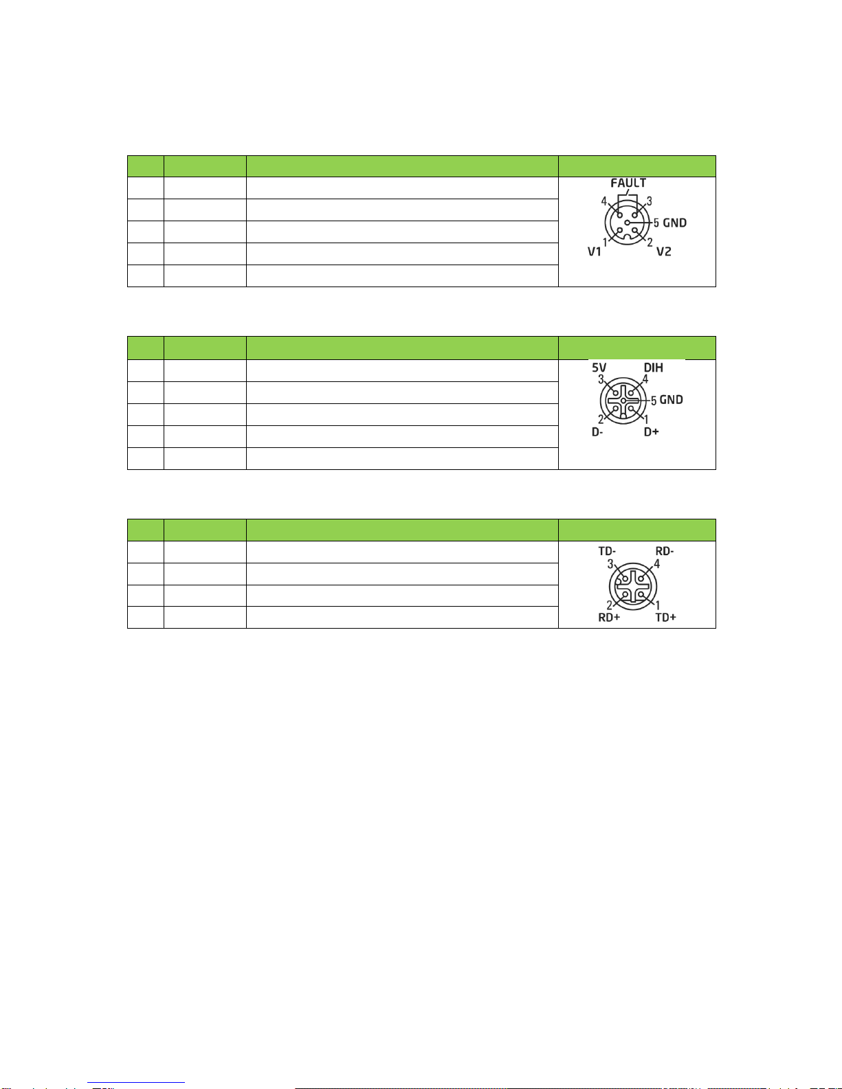
3.2. Connecting of power supply and fault contact
The power supply can be connected either on V1 or on V2. For redundant power supply, connect both
V1 and V2. Please find the electrical data in chapter 6.1.
Pin
Name
Description
Image
1
V1
power supply 1, plus pole
2
V2
power supply 2, plus pole
3
FAULT
Fault Contact
4
FAULT
Fault Contact
5
GND
power supply common minus pole
3.3. Connection of USB port
Pin
Name
Description
Image
1
D+
USB data line D+
2
D-
USB data line D-
3
5V
USB power supply, positive pole
4
DIH
reserved for future application
5
GND
USB power supply, negative pole
3.4. Connection of Ethernet ports
Pin
Belegung
Anschluss
Skizze
1
TD+
Transmit Data +
2
RD+
Receive Data +
3
TD-
Transmit Data -
4
RD-
Receive Data -
4. First start-up
4.1. Default Settings
Order no. 006-130-100
The devices with the Order-Nr. 006-130-100 are unmanaged Switches, therefore no configuration can
be made. After wiring the power supply connection the Switch transfers data on all Ethernet ports.
Order no. 006-130-101/102/104
The device is delivered pre-configured. The factory configuration is chosen so that after switching on
the device sends the data immediately to all Ethernet ports. The following settings are set at the
factory:
►Web interface IP adress: 192.168.1.1
►Web interface user name: admin
►Web interface password: password
►Web interface access: port 1-8

Installation Guide ROQSTAR
Document no. 130-103.44 11/2016 ENG Seite 9 von 16
4.2. Configuration
Proceed as follows for the first commissioning:
Order no. 006-130-101/102/104
1. Connect the power supply.
2. Connect the PC / notebook to one of the Ethernet ports 1-8 of the device.
3. The connected PC / laptop must have the following network settings:
►Order no. 006-130-101/104 IP address: 192.168.1.10/24
►Order no.006-130-102 IP address: get automatically
4. Start the web browser and enter the LAN-IP address of the device.
5. Perform the desired configuration of the device.
6. Connect the Switch with your network devices.
5. LED Display
With the LED display, you can perform an initial, rapid device diagnosis.
5.1. System status LED
Order no. 006-130-100
LED
Colour
Activity
Operating state
V1
-
aus
power supply V1 is not connected
green
lights up
power supply V1 is connected
V2
-
off
power supply V2 is not connected
green
lights up
power supply V2 is connected
Order no. 006-130-101/102/104
LED
Colour
Activity
Operating state
PWR
-
off
Power supply is not connected.
green
lights up
Power supply is connected, device is supplied with power.
green
flashes with 1Hz
Indicates an error of the redundant power supply.
MOD
-
off
Device is off, out of service or device is booting.
green
lights up
Device is ready to operate.
green
flashes with 1Hz
Active web interface session.
green
flashes with
10Hz
Firmware update is being performed or
configuration is loaded / saved.
ERR
-
off
There is no error, device operates properly.
red
flashes with 1Hz
Configuration error:
- false user configuration
red
lights up
Fatal system error. Device is not ready to operate due to:
- memory errors
- not recognized Switch / Phy -
- error in an internal voltage

Installation Guide ROQSTAR
Document no. 130-103.44 11/2016 ENG Seite 10 von 16
5.2. Ethernet port LEDs
Each network port is assigned two LEDs. Their meaning is given in the table below.
LED
Colour
Activity
Operational State
Link
-
none
no network connection, Link-Down
green
lights up
network connection, Link-Up
Act
-
none
no data transfer
yellow
flashes
data transfer with 10/100 MBit / s
6. Technical data
6.1. Electrical
Parameter
min.
typ.
max.
Dim.
Operating voltage (V1, V2) SELV
+9,6
+24
+60
VDC
Reset level (V1, V2)
-
8,0
-
VDC
Current consumption, full load all ports
V1,V2 = 9.6V
V1,V2 = 24V
V1,V2 = 60V
-
-
-
380
161
79
418
186
88
mA
mA
mA
Peak inrush current
<1ms
-
10 @ 9,6V
14 @ 60V
A
Input
V1,V2 = 9.6V
V1,V2 = 24V
V1,V2 = 60V
-
-
-
3,6
3,9
4,7
4,0
4,5
5,3
W
W
W
Bridging of power outage
10
-
-
ms
Internal fuse
2A, T
-
Ethernet-Ports
min.
typ.
max.
Dimension
Switch architecture
Store-and-Forward
Bitrate
-
10 / 100
-
Mbit/s
Output resistance
-
100
-
Input resistance
-
100
-
Latency at 90 % load
at 100 Mbit/s (frame size 64 / 1518 Byte)
at 10 Mbit/s (frame size 64 / 1518 Byte)
-
-
8 / 125
8 / 125
9 / 133
9 / 133
µs
µs
Throughput unicast packets
Frame size 64 –1518 Byte
-
Full wire
speed
-
Frame size
without VLAN Tag
with VLAN Tag
64
64
-
1518
1522
Byte
Byte

Installation Guide ROQSTAR
Document no. 130-103.44 11/2016 ENG Seite 11 von 16
Fault contact
min.
typ.
max.
Dimension
Switching voltage
AC
DC
-
-
-
-
30
60
VAC
VDC
Switching current (SELV)
-
-
2
A
Isolation
min.
typ.
max.
Dimension
Data ports ↔data ports
± 2250
-
-
VDC
Data ports ↔V1, V2, USB, fault contact
± 2250
-
-
VDC
Data ports ↔housing (grounding)
± 2250
-
-
VDC
Fault contact ↔V1, V2, USB, housing
± 1500
-
-
VDC
Housing (grounding) ↔V1, V2, USB
± 850
-
-
VDC
6.2. Mechanical
Parameter
typ.
Dimension
Dimensions (H x B x T, ± 0,5 mm)
121 x 175 x 52
mm
Mass net
530
g
Housing protection class
IP54
-
Mounting
drilled hole for four M4 screws
-
6.3. Environment
Parameter
min.
typ.
max.
Dimension
Ambient temperature during operation
durable
15min
-40
-40
-
-
+70
+85
°C
°C
Ambient temperature storage
-40
-
+85
°C
Humidity (not condensing)
10
-
95
%
Air pressure during operation
690
(3000 m
over NN)
-
-
hPa

Installation Guide ROQSTAR
Document no. 130-103.44 11/2016 ENG Seite 12 von 16
6.4. Standards and approvals
The device is compliant with the following test standard.
►Electromagnetic radiation:
►EN61000-6-4
►EN55022: Class A
►FCC47 CFR Part 15 Class A
►Immunity against conducted interference and external fields:
►EN61000-6-2
►EN61000-4-2
►EN61000-4-3
►EN61000-4-4
►EN61000-4-5
►EN61000-4-6
►Specific applications
►EN50155
►EN50121-4
►EN61131-2
►UNECE (E1) R10
►UNECE (E1) R118
Installation Guide ROQSTAR
Document no. 130-103.44 11/2016 ENG Seite 13 von 16
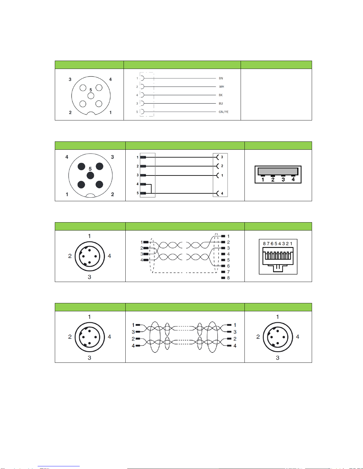
7. Wiring diagrams
7.1. Power cable
Connector
Diagram
Pin assigment*
1
brown
V1
2
white
V2
4
black
Fault
3
blue
Fault
5
yellow/green
GND
* for accessories Order-No. 006-000-003 or 006-000-004
7.2. M12 to USB adapter
M12 Connector
Diagram
USB Connector
7.3. Ethernet M12 to RJ45 cable
M12 connector
Diagram
RJ45 connector
7.4. Ethernet M12 to M12 cable
Connector
Diagram
Connector

Installation Guide ROQSTAR
Document no. 130-103.44 11/2016 ENG Seite 14 von 16
8. Order numbers
8.1. ROQSTAR Ethernet Switches
Order-No.
Product code
Decsription
006-130-100
ROQ-08F-U-LV-IP54
8-Port Fast Ethernet Unmanaged M12 Switch
006-130-101
ROQ-08F-L-LV-IP54
8-Port Fast Ethernet Lite Managed M12 Switch
006-130-102
ROQ-08F-F-LV-IP54
8-Port Fast Ethernet Full Managed M12 Switch
006-130-104
ROQ-08F-E-LV-IP54
8-Port Fast Ethernet Expandable M12 Switch
006-130-103*
ROQ-08F-S-LV-IP54
10-Port Fast Ethernet Security Managed M12 Switch
* not in this document
8.2. Accessories
Order-No.
Description
006-000-003
M12 power supply cable for ROQSTAR Switches, 2m, straight
006-000-004
M12 power supply cable for ROQSTAR Switches, 2m, angled
006-000-042
Ethernet cable CAT5e, M12 to RJ45, 1m
006-000-025
Ethernet cablel CAT5e, M12 to M12, 3m
006-000-007
Adapter cable M12 to USB Typ A Buchse
006-000-008
USB flash drive

Installation Guide ROQSTAR
Document no. 130-103.44 11/2016 ENG Seite 15 von 16
9. Contact
9.1. Technical support
Please concat our support team at suppo[email protected] if you have any technical questions or if you
need technical training.
9.2. Specific product variants
You have a specific problem and you need a product variant that doesn’t exist today. Please contact
us for customer specific adaption of our product. Please visit us at www.tronteq.de.

Installation Guide ROQSTAR
Document no. 130-103.44 11/2016 ENG Seite 16 von 16
TRONTEQ Electronic
Siemensstraße 22
72766 Reutlingen
www.tronteq.de
This manual suits for next models
3
Table of contents
Other TRONTEQ Electronic Network Router manuals


