Trotec AC060V User manual

TRT-BA-AC060V-TC2018-67-001-EN
AC060V
EN
OPERATING MANUAL
THERMAL IMAGING CAMERA

2 EN
thermal imaging camera AC060V
Table of contents
Notes regarding the operating manual.................................2
Safety .....................................................................................2
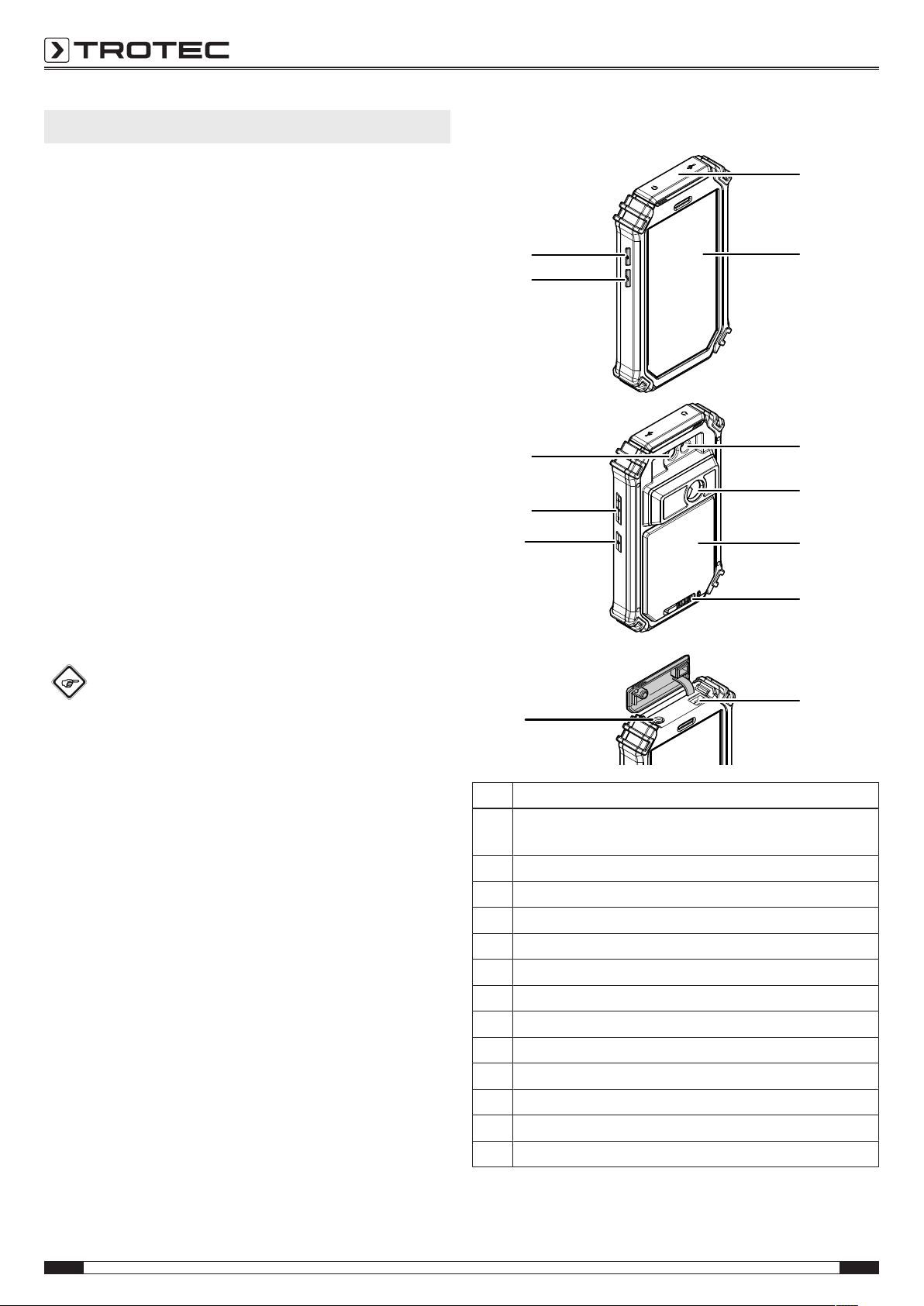
Information about the device................................................4
Transport and storage...........................................................6
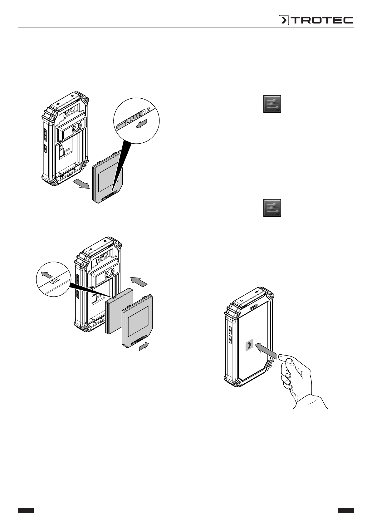
Operation ...............................................................................6
AC060V app............................................................................9
Emissivity.............................................................................17
Errors and faults..................................................................19
Maintenance and repair ......................................................20
Disposal ...............................................................................20
Notes regarding the operating manual
Symbols
Warning of electrical voltage
This symbol indicates dangers to the life and health of
persons due to electrical voltage.
Warning
This signal word indicates a hazard with an average
risk level which, if not avoided, can result in serious
injury or death.
Caution
This signal word indicates a hazard with a low risk
level which, if not avoided, can result in minor or
moderate injury.
Note
This signal word indicates important information (e.g.
material damage), but does not indicate hazards.
Info
Information marked with this symbol helps you to carry
out your tasks quickly and safely.
Follow the manual
Information marked with this symbol indicates that the
operating manual must be observed.
You can download the current version of the operating manual
and the EU declaration of conformity via the following link:
AC060V
https://hub.trotec.com/?id=42959
Safety
Read this manual carefully before starting or using the
device. Always store the manual in the immediate vicinity
of the device or its site of use!
Warning
Read all safety warnings and all instructions.
Failure to follow the warnings and instructions may
result in electric shock, fire and/ or serious injury.
Save all warnings and instructions for future
reference.
This appliance can be used by children aged from
8years and above and persons with reduced physical,
sensory or mental capabilities or lack of experience
and knowledge if they have been given supervision or
instruction concerning use of the appliance in a safe
way and understand the hazards involved.
Children shall not play with the appliance. Cleaning and
user maintenance shall not be made by children
without supervision.
• Do not use the device in potentially explosive rooms.
• Do not use the device in aggressive atmosphere.
• Do not immerse the device in water. Do not allow liquids to
penetrate into the device.
• The device may only be used in dry surroundings and must
not be used in the rain or at a relative humidity exceeding
the operating conditions.
• Protect the device from permanent direct sunlight.
• Do not remove any safety signs, stickers or labels from the
device. Keep all safety signs, stickers and labels in legible
condition.
• Do not open the device with a tool.
• Observe the storage and operating conditions as given in
the Technical data chapter.

EN 3
thermal imaging camera AC060V
Intended use
Only use the device for visual or thermographic representation
of objects whilst adhering to the technical data.
To use the device for its intended use, only use accessories and
spare parts which have been approved by Trotec.
Improper use
Do not use the device in potentially explosive areas. Never use
the device on persons or animals. Trotec accepts no liability for
damages resulting from improper use. In such a case, any
warranty claims will be voided. Any unauthorised modifications,
alterations or structural changes to the device are forbidden.
Personnel qualifications
People who use this device must:
• have read and understood the operating manual, especially
the Safety chapter.
Residual risks
Hazardous electric current
Work on the electrical components must only be
carried out by an electrically skilled person or an
authorised specialist company.
Warning of electrical voltage
There is a risk of a short-circuit due to liquids
penetrating the housing!
Do not immerse the device and the accessories in
water. Make sure that no water or other liquids can
enter the housing.
Warning of electrical voltage
Work on the electrical components must only be
carried out by an authorised specialist company!
Warning of electrical voltage
Before any work on the device, remove the mains plug
from the mains socket and the battery from the device!
Hold onto the mains plug while pulling the power cable
out of the mains socket.
Warning of explosive substances
Do not expose the battery to temperatures above
45°C! Do not let the battery come into contact with
water or fire! Avoid direct sunlight and moisture. There
is a risk of explosion!
Warning
Risk of suffocation!
Do not leave the packaging lying around. Children may
use it as a dangerous toy.
Warning
The device is not a toy and does not belong in the
hands of children.
Warning
Dangers can occur at the device when it is used by
untrained people in an unprofessional or improper way!
Observe the personnel qualifications!
Caution
Keep a sufficient distance from heat sources.
Note
To prevent damages to the device, do not expose it to
extreme temperatures, extreme humidity or moisture.
Note
Do not use abrasive cleaners or solvents to clean the
device.

4 EN
thermal imaging camera AC060V
Information about the device
Device description
The thermal camera AC060V creates a visible image depicting
infrared radiation, which is otherwise invisible to the human
eye. The thermal image and temperature are displayed on the
screen in real time. To improve the view, you can select various
colour palettes for depicting the thermal image.
You are also able to automatically find and display the warmest
and coolest measuring spot in the measured image.
For a measured result which is as precise as possible the
ambient temperature, relative humidity, distance and emissivity
can be entered.
A list of emissivities for various surfaces is provided in the
chapter Emissivity.
For a precise evaluation, the thermal image on the screen can
be recorded and saved on the device.
The device control is based on the Android operating system for
tablets.
The saved images can either be viewed directly on the screen or
transferred to a PC with the supplied USB cable.
To edit the images, you can download the IR-Report 2.X STD
software from the download (or service) section of
www.trotec.com.
Info
This operating manual only describes the operation of
the IR app for the AC060V. Further functions of the
tablet or the Android operating system are not a part of
this manual.
Additionally, to create short reports relating to the images, you
can use the app IR-Wizard available free of charge. This
software is a complimentary bonus that does not belong to the
standard scope of delivery and is offered for use without support
or warranty. The program interface (only available in selected
languages) is generally easily comprehensible and can be used
intuitively. Further information regarding the use is provided in
the application.
Device depiction
1
2
3
4
5
6
7
8
9
10
11
12
13
No. Operating element
1 Protective cover for micro USB and headphone
connection
2 Touchscreen
3 LED illumination
4 Infrared camera
5 Battery compartment with cover
6 Locking mechanism for the battery compartment
7 USB port
8 3.5mm headphone connection
9 Power button
10 Volume control button
11 Camera (visual)
12 Photo button (IR picture)
13 Shutter button

EN 5
thermal imaging camera AC060V
Technical data
Parameter Value
Model AC060V
Article number 3.110.003.030
Measurement Temperature range -20 °C to +160 °C
Accuracy ± 2 °C, ± 2 % from the measured value
Radiometric image
performance
Detector type UFPA
Detector resolution 80 x 80 pixels
Spectral range 8 to 14 µm
Field of vision (FOV) 21° x 21°
Geometric resolution 4.1 mrad
Thermal sensitivity ≤0.1°C at 30°C
Refresh rate 50 Hz
Focus / min. focus distance Rigid / 0.5 m
Visual image
performance
Digital photo camera 8 megapixels, integrated photo lamp(LED)
Video norm PAL / NTSC
Image
representation
Display 5.5-inch LCD touchscreen, capacitive
Image display Pseudo colours, 6 colour palettes (IR image); 16.7 million colours (real image)
Image display options IR image, IR video, real image
Measurement and
analysis
Measuring points 3dynamic temperature measuring points, individually configurable (MIN, MAX, ALARM)
Measuring functions Automatic min./max. temperature tracking (hot/cold spot), isotherm, sector analysis (line,
circle, rectangle), alarm function
Emissivity User-defined variably adjustable from 0.01 to 1.0
Measurement correction Correction of the reflected object temperature; automatic correction based on user-defined
specifications for ambient temperature, distance, relative humidity
System equipment Operating system and functions Operating system based on Android4.2 with integrated thermal image analysis software,
report generating function, IR video player, internet browser
Interfaces USB, WLAN, GPS, Bluetooth, 3.5mm headphone output
Data storage Memory 16 GB integrated and non-exchangeable SD card
File format Radiometric image: 14 bit JPEG; visual image: JPEG; non-radiometric thermographic video:
MPEG-4
Power supply Battery type Standard, lithium-ion; rechargeable
Operating time ≈ 2 h
Surrounding
conditions and
physical
characteristics
Temperature 0 °C to +50 °C (operation), -25 °C to +55 °C (storage)
Type of protection IP54
Shock / vibration 25 G / 2 G
Dimensions 173x 100x 28mm
Weight 415g
Scope of delivery
• 1 x Thermal camera AC060V
• 1 x Rechargeable battery, Li-ion
• 1 x Charger
• 1 x Charging cradle
• 1 x Changing adapter for different socket types
• 1 x USB cable
• 1 x Transport case
• 1x Manual

6 EN
thermal imaging camera AC060V
Transport and storage
Note
If you store or transport the device improperly, the
device may be damaged.
Note the information regarding transport and storage of
the device.
Transport
For transporting the device, use the transport case included in
the scope of delivery in order to protect the device from external
influences.
The supplied Li-ion batteries are subjects to the requirements of
dangerous goods legislation.
Observe the following when transporting or shipping Li-ion
batteries:
• The user may transport the batteries by road without any
additional requirements.
• If transport is carried out by third parties (e.g. air transport
or forwarding company), special requirements as to
packaging and labelling must be observed. This includes
consulting a dangerous goods specialist when preparing
the package.
– Only ship batteries if their housing is undamaged.
– Mask open terminals with tape and pack the battery in
a way that it cannot move inside the packaging.
– Please also observe any other national regulations.
Storage
When the device is not being used, observe the following
storage conditions:
• dry and protected from frost and heat
• protected from dust and direct sunlight
• For storing the device, use the transport case included in
the scope of delivery in order to protect the device from
external influences.
• The storage temperature is the same as the range given in
the Technical data chapter.
• When storing the device for an extended period of time,
remove the battery/batteries.
Operation
Operating elements (AC060V app only)
17
15
16
14
18
19
20
21 23
22
26
25
24
No. Operating elements
14 Settings menu button
15 Temperature scale
16 Camera control panel
17 Mode menu bar
18 Functions menu bar (example here: Analysis)
19 Parameter button
20 Charging status indicator
21 Menu button
22 Home button
23 Back button
24 Still image button
25 Calibration / automatic adjustment button
26 Button to change between IR camera and visual camera

EN 7
thermal imaging camera AC060V
Inserting / Changing the battery
Note
Make sure that the surface of the device is dry and the
device is switched off.
1. Slide the locking bar of the battery compartment to the left.
ðThe battery compartment's lock is released.
2. Remove the cover(5) from the battery compartment.
3. Insert the battery into the compartment as indicated in the
above figure.
4. Reattach the cover(5) to the battery compartment.
5. Slide the locking bar to the right.
ðThe battery compartment is closed and locked.
Switching the device on
1. Press the Power button(9) for approx. 3 seconds.
ðThe display switches on.
ðThe operating system boots up.
ðThe device is ready for operation.
Setting the language
The app's language is controlled via the system settings of the
Android operating system.
1. Call up the system settings. The system settings app has
the following icon:
2. Find the menu item Language & input.
3. Set the desired language.
4. Press the Back button(23) to leave the system settings.
Setting the time and date
Time and date of the app are controlled via the system settings
of the Android operating system.
1. Call up the system settings. The system settings app has
the following icon:
2. Find the menu item Date & Time.
3. Adjust the time and date as desired.
4. Press the Back button(23) to leave the system settings.
Starting the AC060V app
In order to use the IRcamera first start the AC060V app via the
Android user interface.
1. Touch the icon on the user interface.
ðThe app starts.
ðThe IR camera will be activated.
ðThe thermal image will be displayed in real time.
Further information regarding the operation of the app can be
found in the chapter AC060V app.

8 EN
thermal imaging camera AC060V
Calibrating the IRcamera
1. Press the Shutter button(13).
ðThe internal shutter of the IR camera closes briefly and
an automatic adjustment (calibration) to the
temperatures in the image section is performed.
You can also calibrate the IRcamera via the AC060V app. To do
so, please proceed as follows:
1. Start the AC060V app.
2. Press the Calibration button(25).
ðThe internal shutter of the IR camera closes briefly and
an automatic adjustment (calibration) to the
temperatures in the image section is performed.
25
Taking/recording an infrared image/video
1. Start the AC060V app.
2. Change over to the Image or Analysis mode.
3. Point the camera at the object which you want to have a
thermal image of.
4. Calibrate the IR camera (see Calibrating the IRcamera).
5. Either press the Photo button(12) or the camera icon on
the display (Image mode).
Data transfer via USB
1. Connect the supplied micro USB data cable to the device.
2. Connect the data cable to a PC or notebook.
3. If the camera is not recognized by the computer, select the
function use as data store when prompted:
ðTo do so, open the Android USB settings by swiping the
screen from the top edge to the bottom.
ðAfter successful detection the camera is displayed in
the file browser of your PC/notebook as removable
storage device; from there files can be transferred.
Switching the device off
1. Press the Power button(9) for approx. 3 seconds.
2. Confirm the switch-off by pressing the button Power Off.
ðThe device switches off.

EN 9
thermal imaging camera AC060V
AC060V app
Basic settings
In this menu you can set the automatic calibration and view
information regarding the device.
Setting the automatic calibration
You can specify the time after which the camera carries out an
automatic adjustment.
1. Press the Settings button(14).
ðThe menu will be displayed.
2. Touch the selection Auto Shutter Time.
ðThe submenu for setting the time for an automatic
calibration will be displayed.
3. Select the desired time or disable automatic calibration.
4. Press Confirm to confirm and save the selection. If you do
not want to save the change, press Cancel.
5. Press the Back button(23) to leave the menu.
Info
If the automatic adjustment function of the camera is
deactivated, it needs to be calibrated manually at
regular intervals during operation, particularly before
taking a picture, as owing to its operating principle the
IR detector drifts and the camera could consequently
display incorrect temperature values!
Displaying device information
1. Press the Settings button(14).
ðThe menu will be displayed.
2. Select Device Info.
ðThe device information will be displayed.
3. Press the Back button(23) to leave the device information.
Advanced settings
1. Press the Parameter button(19).
ðThe parameter menu bar will be displayed.
32
31
30

10 EN
thermal imaging camera AC060V
2. Press the desired button to access the corresponding
menu:
ðNo.(30) calls up the Parameter menu.
ðNo.(31) calls up the Colour settings menu.
ðNo.(32) calls up the Photo settings menu.
3. Press the Back button(23) to close the menu bar.
Parameter menu
In this menu you can adjust general parameters such as the
ambient temperature or the emissivity.
1. Touch the parameter you want to edit.
ðA submenu with setting options for the selected
parameter will be displayed. Displayed in our example is
the submenu for the ambient temperature.
ðThe following parameters can be selected:
Ambi. Temperature = Setting the ambient temperature
Humidity = Setting the humidity level
Emissivity = Setting the emissivity
Distance = Setting the distance to the measuring object
Refl. Temperature = Setting the average value of the
reflected temperatures from heat sources located in the
background, which could influence the object to be
thermographed.
Unit Settings = Setting the units used (metric, imperial)
Temperature Level = Setting the measuring range
2. Select the desired value for the parameter.
3. Press Confirm to confirm and save the selection. If you do
not want to save the change, press Cancel.
4. Press the Back button(23) to leave the menu or briefly
touch a free area on the touch screen.
Colour settings submenu
In this submenu you can select the colour palette for the
representation of the temperatures in the thermal image.
1. Press the button with the desired setting. The colour
palette will be applied immediately and is visible in the
background.
2. Press the Back button(23) to leave the submenu or briefly
touch a free area on the touch screen.
ðThe settings will be saved.

EN 11
thermal imaging camera AC060V
Photo settings submenu
In this submenu you can adjust the thermal image display.
1. Press the button with the desired setting. Selected in this
example is the setting Original Image.
ðThe following parameters can be selected:
Original Image = Image is depicted normally.
Image Smooth = Image is blurred.
Detail Enhance = Image is depicted with a higher
resolution.
2. Press the Back button(23) to leave the submenu or briefly
touch a free area on the touch screen.
ðThe settings will be saved.
Analysis mode
In the analysis mode points, lines or areas can be marked on
the display to be analysed in real time.
1. Enable analysis mode by pressing the Analysis button in
the Mode menu bar(17).
33 34 35 36
17
24
2. You can press the Still image button(24) to freeze an
image for analysis.
Point analysis
1. Press the button for points(33).
ðCrosshairs appear on the display beside which the
current temperature of the point is indicated.
2. Touch the specific display location to select the point to be
analysed.
ðThe button for points(33) will be enabled.
ðThe button is now displayed as crosshairs with a recycle
bin(37).
ðIn order to delete the point, drag it to the corresponding
button with the recycle bin(37).
37

12 EN
thermal imaging camera AC060V
3. Touch a selected measuring spot for approx. one second;
then a submenu opens in which the selected measuring
spot can be individually configured as follows:
ðAlarm: visual and acoustic alarm signal when falling
below (Below), exceeding (Above) or hitting (Equal) a set
alarm temperature precisely.
ðMax: locates the hottest point in the image section
ðMin: locates the coldest point in the image section
4. Press Confirm to confirm and save the selection. If you do
not want to save the change, press Cancel.
Area analysis
On the screen you can draw up to two rectangular or circular
areas respectively to carry out a separate area analysis within
the thermogram.
1. Press the button for rectangles(35) or circles(36).
2. Touch the starting point on the display and then stretch the
rectangle or circle to be analysed.
ðThe rectangle or circle appears on the screen. Displayed
in the top left corner of the screen is a panel indicating
the maximum, minimum and average measured values
within the area (R stands for rectangle, C for circle).
ðTo adjust the size or direction of the respective area,
touch one of the corners or the line and drag it to the
desired shape/size.
ðTo relocate an area in its entirety on the screen, touch
its centre and drag it to the desired position.
ðThe button for rectangles or circles will be enabled.
ðThe button is now displayed with a recycle
bin(example: rectangle(38)).
ðIn order to delete the point, drag it to the corresponding
button with the recycle bin.
38
3. Touch the centre of a selected rectangular or circular area
for approx. one second; then a submenu opens in which
the maximum, minimum or average value can be
(de-)activated.
4. Press Confirm to confirm and save the selection. If you do
not want to save the change, press Cancel.

EN 13
thermal imaging camera AC060V
Line analysis
1. Press the button for lines(34).
ðThe line appears on the display. Above and below the
line the temperature profile is displayed in form of a
chart in the below thermogram area.
ðTo relocate the line analysis, touch the analysis field and
drag it to the desired thermogram area.
ðThe button for lines(34) will be enabled.
ðThe button is now displayed with a recycle bin(39).
ðIn order to delete the line, drag it to the corresponding
button with the recycle bin.
39
Image mode
Via the image mode you can take pictures or record videos and
make further settings regarding the images generated by the
IR camera.
1. Enable image mode by pressing the Image button in the
Mode menu bar(17).
40 41 42 43
17
Taking a picture
1. Press the Camera button(42).
ðThe picture is taken and saved.
Recording a video
1. Press the Video button(43).
ðThe recording starts.
ðThe duration of the recording is displayed above the
Mode menu bar.
2. Press the Video button(43) again (now displayed as pause
symbol) to stop recording.
ðThe video will be saved.
Setting brightness and contrast
1. Press the L/S button(40).
ðThe brightness and contrast menu (LEVEL & SPAN) will
be displayed.
Contrast (SPAN):
set temperature range (e.g. from 5°C to 30°C
=> SPAN = 25°C)
Brightness (LEVEL):
average temperature referring to the set temperature
range (in accordance with the above example
= 17.5°C)

14 EN
thermal imaging camera AC060V
By reducing and shifting the span even the slightest of
temperature differences can be visualized in practice,
for instance for the localization of subsurface hot water
pipes, specific structural-physical problems or industrial
applications.
ðThe following parameters can be selected:
Auto Level&Span = Brightness and contrast are
automatically adjusted.
Auto Level = The brightness is automatically adjusted.
The contrast can be entered manually.
Auto Span = The brightness is automatically adjusted.
The brightness can be entered manually.
Manual Level&Span = Brightness and contrast are
adjusted manually.
2. Select the desired settings for brightness and contrast and
enter the values by hand, if required. In addition to the
manual input of direct numerical values, both brightness
(LEVEL) and contrast (SPAN) can also be adjusted fluently
by swiping the screen.
ðContrast (SPAN):
– Swiping down reduces the span and increases the
contrast.
– Swiping up increases the span and reduces the
contrast.
ðBrightness (LEVEL):
– Swiping right increases the average temperature.
The image turns darker.
– Swiping left decreases the average temperature.
The image turns brighter.
3. Press Confirm to confirm and save the selection. If you do
not want to save the change, press Cancel.
Setting ISO mode
Isotherms are colours of the same temperature. In this mode the
thermal imaging camera highlights all areas within a certain
previously specified temperature range (isotherm window) by
means of a selected, particularly noticeable colour. This can e.g.
be drops below dew point at building surfaces or thermally
critical areas in control cabinets etc.
1. Press the ISO button(41).
ðThe ISO mode menu will be displayed.
ðThe following parameters can be selected:
Between = The isotherm window is situated in between
the minimum and the maximum temperature of the
currently displayed temperature scale of the camera.
It can be varied freely by dragging the upper and lower
limits (arrow).
Above = The isotherm window starts at the upper end
of the temperature scale and can only be varied by
dragging the lower limit.
Below = The isotherm window starts at the bottom end
of the temperature scale and can only be varied by
dragging the upper limit.
ISO Color Picker = Select an isotherm colour from the
ring. Touch the centre of the ring to confirm your
selection.
2. Select the desired settings.
3. Press Confirm to confirm and save the selection. If you do
not want to save the change, press Cancel.

EN 15
thermal imaging camera AC060V
Example ISO Mode: Between
Example ISO Mode: Below
Example ISO Mode: Above

16 EN
thermal imaging camera AC060V
File mode
In file mode you can view already taken/recorded pictures or
videos.
1. Enable file mode by pressing the File button in the Mode
menu bar(17).
17
ðThe file browser opens.
2. Select a folder.
ðThe images and/or videos in the folder are displayed in
a list.
3. Select a file.
ðThe file will be displayed on the screen.

EN 17
thermal imaging camera AC060V
Emissivity
The emissivity is used to describe the energy radiation
characteristic of a material (see also chapter Thermography
terms).
A material's emissivity depends on various factors:
• composition,
• surface condition,
• temperature.
The emissivity can range between 0.01 and 1 (in theory). The
following rule of thumb can be assumed:
• When a material is rather dark and its surface texture matt,
it probably has a high emissivity.
• The brighter and smoother the surface of a material, the
lower will be its emissivity, presumably.
• The higher the emissivity of the surface to be measured,
the better it is suited for non-contact temperature
measurement by use of a pyrometer or thermal imaging
camera, since falsifying temperature reflections can be
neglected.
Entering an emissivity as accurate as possible is indispensable
for a precise measurement.
Most organic materials have an emissivity of 0.95. Metals or
shiny materials come with a much lower value.
Material Temperature (°C) Emissivity
(approximate)
Aluminium
Polished aluminium 100 0.09
Customary
aluminium foil
100 0.09
Electrolytically
chromium-plated
aluminium oxide
25 – 600 0.55
Mild aluminium oxide 25 – 600 0.10 – 0.20
Strong aluminium
oxide
25 – 600 0.30 – 0.40
Iron
Polished cast iron 200 0.21
Processed cast iron 20 0.44
Polished tempered
iron
40 – 250 0.28
Polished steel ingot 770 – 1040 0.52 – 0.56
Raw, welded steel 945 – 1100 0.52 – 0.61
Surface iron oxide 20 0.69
Fully rusted surface 22 0.66
Rolled iron plate 100 0.74
Oxidized steel 198 – 600 0.64 – 0.78
Material Temperature (°C) Emissivity
(approximate)
Cast iron
(oxidizing at 600 °C)
198 – 600 0.79
Steel
(oxidizing at 600 °C)
125 – 520 0.78 – 0.82
Electrolytic iron oxide 500 – 1200 0.85 – 0.95
Iron plate 925 – 1120 0.87 – 0.95
Cast iron, heavy iron
oxide
25 0.80
Tempered iron, iron
oxide
40 – 250 0.95
Melting surface 22 0.94
Molten cast iron 1300 – 1400 0.29
Molten structural
steel
1600 – 1800 0.28
Liquid steel 1500 – 1650 0.28
Pure iron ore 1515 – 1680 0.42 – 0.45
Galvanized, shiny
iron plate
28 0.23
Copper
Copper oxide 800 – 1100 0.13 – 0.16
Copper mirror 100 0.05
Strong copper oxide 25 0.078
Liquid copper 1080 – 1280 0.13 – 0.16
Brass
Brass mirror 28 0.03
Brass oxide 200 – 600 0.59 – 0.61
Chromium
Polished chrome 40 – 1090 0.08 – 0.36
Gold
Gold mirror 230 – 630 0.02
Silver
Polished silver 100 0.05
Nickel
Nickel chromium
(heat-resistant)
50 – 1000 0.65 – 0.79
Nickel chromium
alloy
50 – 1040 0.64 – 0.76
Nickel chromium
alloyed
(heat-resistant)
50 – 500 0.95 – 0.98
Nickel silver alloy 100 0.14

18 EN
thermal imaging camera AC060V
Material Temperature (°C) Emissivity
(approximate)
Polished, galvanized 25 0.05
Galvanized 20 0.01
Nickel wire 185 – 1010 0.09 – 0.19
Lead
Pure lead
(not oxidized)
125 – 225 0.06 – 0.08
Stainless steel
18 -8 25 0.16
304 (8Cr, 18Ni) 215 – 490 0.44 – 0.36
310 (25Cr, 208Ni) 215 – 520 0.90 – 0.97
Tin
Finished tin plate 100 0.07
Heavily oxidized 0 – 200 0.60
Zinc
Oxidizing at 400°C 400 0.01
Zinc oxide ash 25 0.28
Magnesium
Magnesia 275 – 825 0.20 – 0.55
Metallic materials
Hg 0 – 100 0.09 – 0.12
Sheet metal 0.88 – 0.90
Non-metallic materials
Brick 1100 0.75
Fire brick 1100 0.75
Graphite (lamp black) 96 – 225 0.95
Porcelain enamel
(white)
18 0.90
Asphaltum 0 – 200 0.85
Glass (surface) 23 0.94
Lime paint 20 0.90
Oak 20 0.90
Piece of coal 0.85
Isolation piece 0.91 – 0.94
Glass tube 0.90
Porcelain enamel
products
0.90
Porcelain enamel
designs
0.83 – 0.93
Solid materials 0.80 – 0.93
Ceramic (vase) 0.90
Film 0.90 – 0.93
Heat-resistant glass 200 – 540 0.85 – 0.95
Material Temperature (°C) Emissivity
(approximate)
Mica 0.94 – 0.95
Glass 0.91 – 0.92
Level chalk layer 0.88 – 0.93
Epoxy glass plate 0.86
Epoxy
hydroxybenzene
plate
0.80
Electric materials
Semiconductor 0.80 – 0.90
Transistor
(plastic sealed)
0.30 – 0.40
Transistor
(metal diode)
0.89 – 0.90
Gold-plated copper
sheet
0.30
Soldered plated
copper
0.35
Zinc-plated lead wire 0.28
Brass wire 0.87 – 0.88

EN 19
thermal imaging camera AC060V
Errors and faults The device has been checked for proper functioning several
times during production. If malfunctions occur nonetheless,
check the device according to the following list.
Fault Cause Remedy
Abortion of the AC060V app. The software has crashed. Start the software again.
Camera does not take/record
pictures/videos.
Internal memory full. Delete files no longer needed to free
up storage space.
Battery quickly discharged. Battery too old or damaged. Use a new battery.
Battery not charging. Charging cable not inserted
correctly.
Check the connection for proper fit.
Battery too old or damaged. Use a new battery.
Contacts dirty. Use a dry, clean cloth to clean the
contacts.

20 EN
thermal imaging camera AC060V
Maintenance and repair
Charging the battery
Warning of electrical voltage
Before each use of the charger or power cable, check
for damages. If you notice damages, stop using the
charger or power cable!
Charge the battery when the charging status indicator(20) falls
below 10 %, when the device prompts you to or can no longer
be switched on. Ideally the battery is always charged by use of
the charger included in the scope of delivery. Only use the
supplied charger to do so! If the camera needs to be used while
charging, please proceed as follows:
1. Plug the charger into a sufficiently fused power socket.
Only use the original charger or one with identical
specifications, for otherwise both battery and camera
could be damaged!
2. Open the protective cover for the micro USB connection(1)
at the device.
3. Connect the charger to the micro USB connection.
4. Disconnect the charging cable again, once the charging
status indicates 100 %.
Changing the battery
To change the battery, please proceed as described under
Inserting the battery. Remove the old battery before inserting a
new one.
Cleaning
Clean the device with a soft, damp and lint-free cloth. Make
sure that no moisture enters the housing. Do not use any
sprays, solvents, alcohol-based cleaning agents or abrasive
cleaners, but only clean water to moisten the cloth.
Repair
Do not modify the device or install any spare parts. For repairs
or device testing, contact the manufacturer.
Disposal
The icon with the crossed-out waste bin on waste
electrical or electronic equipment stipulates that this equipment
must not be disposed of with the household waste at the end of
its life. You will find collection points for free return of waste
electrical and electronic equipment in your vicinity. The
addresses can be obtained from your municipality or local
administration. For further return options provided by us please
refer to our website www.trotec24.com.
The separate collection of waste electrical and electronic
equipment aims to enable the re-use, recycling and other forms
of recovery of waste equipment as well as to prevent negative
effects for the environment and human health caused by the
disposal of hazardous substances potentially contained in the
equipment.
Li-Ion
In the European Union, batteries and accumulators must not be
treated as domestic waste, but must be disposed of
professionally in accordance with Directive 2006/66/EC of the
European Parliament and of the Council of 6September 2006
on batteries and accumulators. Please dispose of batteries and
accumulators according to the relevant legal requirements.
Other manuals for AC060V
2
Table of contents
Other Trotec Thermal Camera manuals