Panasonic TC0938450-015CE User manual

Operating Instructions
Thermal Camera
Model numbers:
TC0938450-015CE
TC0938450-019CE
TC0938450-025CE
TC0938450-045CE
TC2538450-015CE
TC2538450-019CE
TC2538450-025CE
TC2538450-045CE
TC0964070-025CE
TC0964070-045CE
TC2564070-025CE
TC2564070-045CE
Before attempting toconnect or operate this product, please read these instructions carefully and savethis manual
for future use.

2
Operating Instructions
Preface
About the user manuals
There are 2 sets of operating instructions for the Thermal Camera as follows.
•Installation Guide: Explains the physical installation of the Thermal Camera
•Operating Instructions: Explains how to perform the settings and how to operate this unit.
Trademarks and registered trademarks
•Microsoft, Windows, Windows Vista, Internet Explorer, ActiveX and DirectX are either registered
trademarks or trademarks of Microsoft Corporation in the United States and/or other countries.
•Microsoft product screen shot(s) reprinted with permission from Microsoft Corporation.
•iPad, iPhone, and iPod touch are trademarks of Apple Inc., registered in the U.S. and other countries.
•Android is a trademark of Google Inc.
•Firefox is a registered trademark of the Mozilla Foundation.
•All other trademarks identified herein are the property of their respective owners.
Abbreviations
The following abbreviations are used in these operating instructions.
Microsoft® Windows® 7 is described as Windows 7.
Microsoft® Windows Vista® is described as Windows Vista.
Microsoft® Windows® XP SP3 is described as Windows XP.
Windows® Internet Explorer® 9.0, Windows® Internet Explorer® 8.0, Windows® Internet Explorer® 7.0 and
Microsoft® Internet Explorer® 6.0 are described as Internet Explorer.
Universal Plug and Play is described as UPnP™.
Important Information for Thermal Cameras
Export Regulation
Panasonic Integrated Products may not be used in the design,
development, production or use in nuclear, chemical, or biological weapons or missiles. They may not
be sold, transferred, or exported to Cuba, Iran, Libya, North Korea, Sudan, or Syria*.
Uncooled thermal imaging cameras operating at less than 9 frames per second (9Hz) do not require
an export license.
Panasonic reserves the right to request an end use statement or end user information for the sale of
any Thermal Camera product.
* Please visit Panasonic web site for updated details –see link below
General Information
For Panasonic support please call
+44 (0) 870 600 1620
+44 (0) 870 907 0909
WARNING –this is an EN55022:2010 Class A Product. In a domestic environment this product may cause
radio interference in which case the user may be required to take adequate measures.

Operating Instructions
3
Viewer Software
Viewer software
It is necessary to install the viewer software “Network Camera View 4S” (ActiveX®) to display images on a PC.
This software can be installed directly from the unit or downloaded from the Panasonic website.
IMPORTANT
•The default setting of “Automatic installation of viewer software” is “On”. Follow the instructions in
section 19 when the message is displayed on the information bar of the browser.
•When the “Live” page is displayed for the first time, the install wizard of the ActiveX control required to
display images from the camera will be displayed. Follow the instructions of the wizard.
•When the install wizard is displayed again even after completing the installation of the ActiveX, restart
the PC.
•The viewer software used on each PC should be licensed individually. The number of installations of
the viewer software from the unit can be checked on the [Upgrade] tab of the “Maintenance” page
(section 15
). Refer to your dealer for the software licensing.

4
Operating Instructions
Contents
1 Monitor images on a PC................................................................................................................7
1.1 Monitor images from a single camera ........................................................................................7
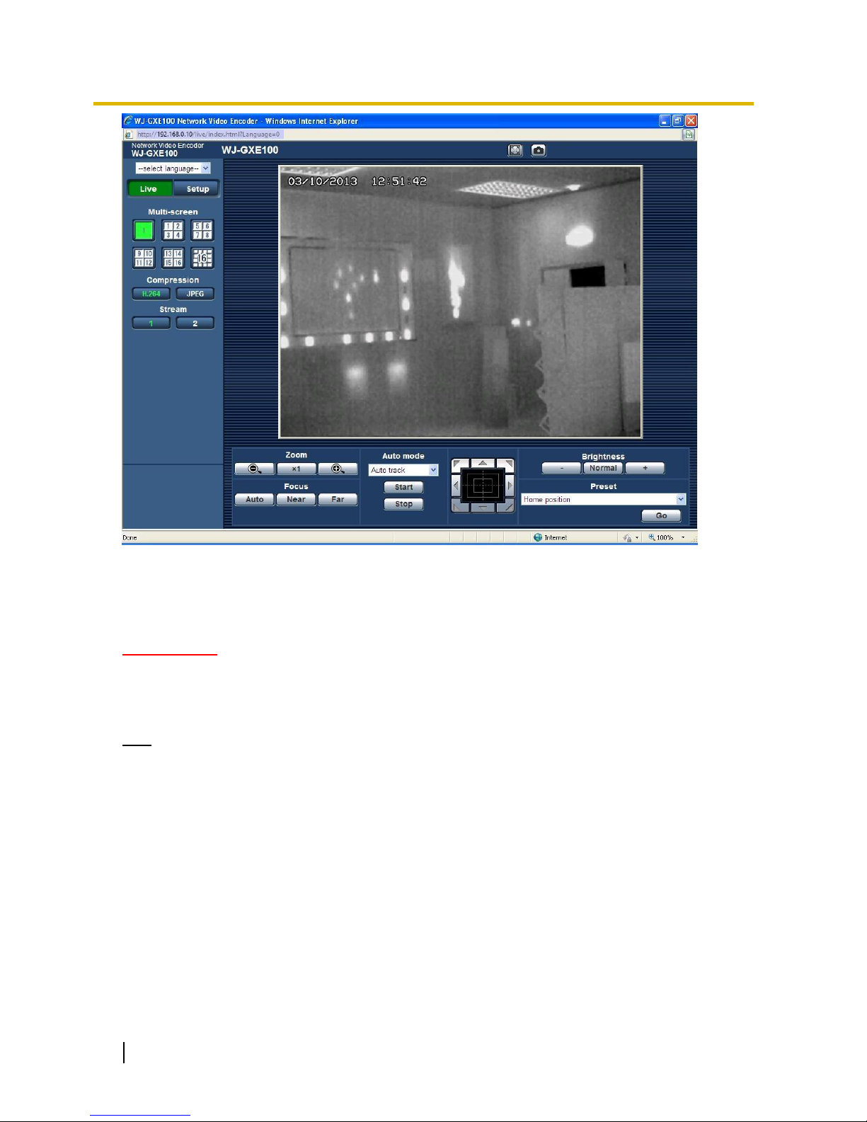
1.2 About the “Live” page.................................................................................................................9
1.3 Monitor images from multiple cameras.....................................................................................11
2 Monitor images on a cellular phone/mobile terminal....................................................................13
2.1 Monitor images on a cellular phone..........................................................................................13
2.2 Monitor images on a mobile terminal........................................................................................14
3 Action at an alarm occurrence.....................................................................................................17
3.1 Alarm type................................................................................................................................17
3.2 Action at an alarm occurrence..................................................................................................17
4 Transmit images onto an FTP server...........................................................................................18
4.1 Transmit an alarm image at an alarm occurrence (Alarm image transmission) ........................18
4.2 Transmit images at a designated interval or period (FTP periodic image transmission) ...........18
5 About the network security ..........................................................................................................19
5.1 Equipped security functions .....................................................................................................19
6 Display the setup menu from a PC..............................................................................................20
6.1 How to display the setup menu................................................................................................20
6.2 How to operate the setup menu...............................................................................................21
6.3 About the setup menu window.................................................................................................23
7 Configure the basic settings of the unit [Basic] ............................................................................25
7.1 Configure the basic settings [Basic] .........................................................................................25
7.2 Configure the Internet settings [Internet] ..................................................................................27
8 Configure the settings relating to images [Image]........................................................................30
8.1 Configure the settings relating to the Picture (Camera) mode/Video input [JPEG/H.264]........30
8.2 Configure the settings relating to JPEG images [JPEG/H.264].................................................30
8.3 Configure the settings relating to H.264 images [JPEG/H.264] ................................................31
8.4 Configure the settings relating to image and positions [Image/Position]...................................35
8.5 Configure the settings relating to RS485 [RS485]....................................................................36
9 Configure the multi-screen settings [Multi-screen] .......................................................................37
10 Configure the alarm settings [Alarm].............................................................................................39
10.1 Configure the settings relating to the alarm action [Alarm] .......................................................39
10.2 Configure the settings relating to the alarm image [Alarm] .......................................................39
10.3 Configure the VMD settings [VMD area] ..................................................................................41
10.3.1 Set the VMD areas [VMD area].........................................................................................43
10.4 Configuration of the settings relating to the E-mail notification [Notification].............................45
10.5 Configure the settings relating to Panasonic alarm protocol [Notification] ................................46
11 Configure the settings relating to the authentication [User mng.]..................................................48
11.1 Configure the settings relating to the user authentication [User auth.]......................................48

Operating Instructions
5
11.2 Configure the settings relating to the host authentication [Host auth.]......................................49
11.3 Configure the settings relating to the priority stream [System]..................................................50
12 Configure the settings of the servers [Server]...............................................................................52
12.1 Configure the settings relating to the E-mail server [E-mail].....................................................52
12.2 Configure the settings relating to the FTP server [FTP]............................................................53
12.3 Configure the settings relating to the NTP server [NTP]...........................................................54
13 Configuring the network settings [Network]...................................................................................56
13.1 Configure the network settings [Network].................................................................................56
13.2 Configure the HTTPS settings..................................................................................................63
13.2.1 Generation of the CRT key (SSL encryption key)..............................................................64
13.2.2 Generation of the self-signed certificate (security certificate) ............................................65
13.2.3 Generation of CSR (Certificate Signing Request)..............................................................67
13.2.4 Installation of the server certificate....................................................................................68
13.2.5 Configuration of the connection protocol...........................................................................69
13.3 Access the unit using the HTTPS protocol...............................................................................70
13.3.1 Install the security certificate.............................................................................................70
13.4 Configure the settings relating to DDNS [DDNS]......................................................................79
13.4.1 Configuration of the DDNS service (Example of the “Viewnetcam.com” service) ..............80
13.4.2 When using the “Viewnetcam.com” service.......................................................................81
13.4.3 Procedure to register information for the “Viewnetcam.com” service.................................81
13.4.4 Checking the information registered for the “Viewnetcam.com” service ............................84
13.4.5 When using “Dynamic DNS Update” .................................................................................84
13.4.6 When using “Dynamic DNS Update(DHCP)”.....................................................................84
13.5 Configure the settings relating to SNMP [SNMP] .....................................................................84
13.6 Configure the settings relating to the FTP periodic image transmission [FTP img. trans.] ........85
13.7 Configure the schedule settings of the FTP periodic image transmission [FTP img. trans.]......87
13.7.1 How to set the schedules..................................................................................................87
13.7.2 How to delete the set schedule.........................................................................................88
14 Configure the settings relating to the schedules [Schedule]..........................................................90
15 Maintenance of the unit [Maintenance].........................................................................................92
15.1 Check the system log [System log] ..........................................................................................92
15.2 Upgrade the firmware [Upgrade]..............................................................................................92
15.3 Check the status [Status].........................................................................................................94
15.4 Reset the settings/Reboot the unit [Default reset] ....................................................................95
16 Number of users that can concurrently access the unit.................................................................96
17 Using the IP Setting Software.......................................................................................................97
18 About the displayed system log....................................................................................................99
19 Troubleshooting..........................................................................................................................102

6
Operating Instructions
Appendix A –Introduction to Thermal Imaging ................................................................................108
A.1 Light Basics................................................................................................................................108
A.2 Uncooled infrared detectors .......................................................................................................108
A.3 Atmospheric conditions and their effect of Thermal Imaging.......................................................109
A.3.1 Humidity;..............................................................................................................................109
A.3.2 Fog, rain & snow:.................................................................................................................109
A.4 Examples of Thermal Images.....................................................................................................109
Appendix B –Hyperfocal Distance ..................................................................................................111
B.1 Hyperfocal Distance Table. ........................................................................................................111

Operating Instructions
7
1 Monitor Images on a PC
1 Monitor images on a PC
The following are descriptions of how to monitor images from the camera on a PC.
1.1 Monitor images from a single camera
1. Start up the web browser.
2. Enter the IP address designated using the Panasonic “IP Setting Software” in the address box of the
browser.
Example when entering an IPv4 address: http://URL registered using IPv4 address
http://192.168.0.10/
Example when entering an IPv6 address: http://[URL registered using IPv6 address]
http://[2001:db8::10]/
<Example of IPv4 access>
<Example of IPv6 access>
IMPORTANT
When the HTTP port number is changed from “80”, enter “http://IP address of the unit + : (colon)+ port
number” in the address box of the browser. (Example: http://192.168.0.11:8080)
When the PC is in a local network, configure the proxy server setting of the web browser (under [Internet
Options...] under [Tools] of the menu bar) to bypass the proxy server for the local address.
Note
Refer to section 13.3 for further information about the case in which “HTTPS” is selected for “HTTPS” -
“Connection” on the [Network] tab of the “Network” page
(section 13
).
3. Press the [Enter] key on the keyboard.
The “Live” page will be displayed. Refer to section 1.2 for further information about the “Live” page.

8
Operating Instructions
1 Monitor Images on a PC
When “On” is selected for “User auth.”, the authentication window will be displayed before displaying live
images for the user name and password entries. The default user name and password are as follows:
User name: admin
Password: 12345
IMPORTANT
•Toenhancethe security,changethe passwordforthe username“admin”. Itisrecommendedtochange this
password periodically.
•When displaying multiple H.264 images on a PC, images may not be displayed depending on the
performance of the PC.
Note
•The maximum number of concurrent access user is 14 including users who is receiving H.264 images and
users who are receiving JPEG images. Depending on the set values for “Bandwidth control(bit rate)” and
“Max bit rate (per client)”, the maximum concurrent access number may be 14 or less users. When 14 users
are concurrently accessing, the access limit message will be displayed for users who subsequently attempt
to access. When “Multicast” is selected for “Transmission type” of “H.264”, only the first user who accessed
to monitor H.264 images will be included in the maximum number. The second and subsequent users who
are monitoring H.264 images will not be included in the maximum number.
•When “On” is selected for “H.264 transmission”
(section 8.3
), H.264 images will be displayed. When “Off” is
selected, a JPEG image will be displayed. It is possible to display a JPEG image even when “On” is
selected for “H.264 transmission”. In this case, the refresh interval of JPEG images will be limited.
•The refresh interval may become longer depending on a network environment, PC performance,
photographic subject, access traffic, etc.
<Refresh interval of JPEG images>
When “On” is selected for “H.264 transmission”
Max. 4.2 fps
When “Off” is selected for “H.264 transmission”
Max. 25 fps

Operating Instructions
9
1 Monitor Images on a PC
1.2 About the “Live” page
A[select language] pull-down-menu
The unit’s display language can be selected. The default language can be set in the [Language] in the [Basic]
settings.
(
section 7)
B[Setup] button*1
Displays the setup menu. The button will turn green and the setup menu will be displayed.
C[Live] button
Displays the “Live” page. The button will turn green and the “Live” page will be displayed.
D[Multi-screen] buttons
Images from multiple cameras can be displayed on a multi-screen by registering units/network cameras on the
setup menu.
(
section 1.3)
E[Compression] buttons
•[H.264] button: The characters “H.264” on the button will turn green and an H.264 image will be
displayed. When “On” is selected for “H.264 transmission” of “H.264(1)”, “H.264(2)”, the [H.264] button will
be displayed.
(
section 8.3)
•[JPEG] button: The characters “JPEG” on the button will turn green and a JPEG image will be displayed.
F[Stream] buttons
These buttons will be displayed only when an H.264 image is displayed.
•[1] button: The character “1” will turn green and images in the main area will be displayed in accordance
with the setting of “H.264(1)”.
(
section 8.3)
•[2] button: The character “2” will turn green and images in the main area will be displayed in accordance
with the setting of “H.264(2)”.
(
section 8.3)

10
Operating Instructions
1 Monitor Images on a PC
G[Image capture size] buttons
These buttons will be displayed only when a JPEG image is displayed.
[VGA]
The characters “VGA” will turn green and images in the main area
will be displayed in VGA size.
[QVGA]
The characters “QVGA” will turn green and images in the main area
will be displayed in QVGA size.
[D1]
This option is not supported by the Thermal Camera
H[Image quality] buttons
These buttons will be displayed only when a JPEG image is displayed.
[1] button: Images in the main area will be displayed in accordance with the setting for “Quality1” of
“Image quality setting”.
(
section 8.2)
[2] button: Images in the main area will be displayed in accordance with the setting for “Quality2” of
“Image quality setting”.
(
section 8.2)
I[Zoom] buttons*2
: Click this button to adjust the zoom ratio to the “Wide” side.
: Click this button to set the zoom ratio to x1.0.
: Click this button to adjust the zoom ratio to the “Tele” side.
J[Focus] buttons
This feature is not supported on the Thermal Camera
K[Auto mode]
This feature is not supported on the Thermal Camera
LControl pad/buttons*2
Left-click on the control pad or buttons to adjust the horizontal/vertical position of the camera (panning/
tilting). Panning/tilting speed will be faster if a clicked point gets farther from the center point of the
control pad.
It is also possible to pan/tilt the camera by dragging the mouse.
Zoom and focus can be adjusted by right-clicking. When an upper/lower area of the control pad is right-
clicked, the displayed image will be zoomed in/out on. When a left/right area is right-clicked, the focus
will be adjusted to the Near/Far side.
Zoom can also be adjusted using the mouse wheel.
Note that the Thermal Camera does not support optical zoom or physical pan/tilt –the Pan/Tilt/Zoom
controls are digital only, within an existing image.
M[Brightness] buttons
Left click on the “+” and “–” buttons to cycle through the different display options available:
Greyscale (White hot)
Greyscale (Black hot)
Ironbow
Left-click on the “Normal” button to return to the default value: Greyscale (White hot)
N[Preset]
This feature is not supported on the Thermal Camera
OUnit title
The title entered for “Unit title” on the [Basic] tab will be displayed.
(
section 7.1)

Operating Instructions
11
1 Monitor Images on a PC
PAlarm occurrence indication button*2
This button will be displayed and will blink when an alarm has occurred. When this button is clicked, this button
will disappear.
(
section 3)
QFull screen button
Images will be displayed on a full screen. Toreturn to the “Live” page, press the [Esc] key. The aspect ratio of
displayed images will be adjusted in accordance with the monitor.
RSnap shot button
Click this button to take a picture (a still picture). The picture will be displayed on a newly opened window. When
right-clicking on the displayed image, the pop-up menu will be displayed. It is possible to save the image on the
PC by selecting “Save” from the displayed pop-up menu.
When “Print” is selected, printer output is enabled.
Note
For the case of using Windows 7 or Windows Vista, the following settings may be required.
Open Internet Explorer, click [Tools]
[Internet Options]
[Security]
[Trusted Sites]
[Sites].
Register the unit address on [Website] of the displayed trusted widows.
SMain area
Images from the camera will be displayed in this area.
The current time and date will be displayed according to the settings configured for “Time display format”
and “Date/time display format”.
(
section 7.1)
When clicking a desired point while displaying live images in the main area, the camera will move to locate the
clicked point at the center of the main area.
Note
When operated by a lower access level user, images displayed on the screen may be changed temporarily.
This does not affect operation of the unit.
Depending on the PC in use, screen tearing* may occur when the shooting scene drastically changes due
to the GDI restrictions of the OS.
*A phenomenon in which portions of the screen are displayed out of alignment.
*1 Only operable by users whose access level is “1. Administrator”.
*2 Only operable by users whose access level is “1. Administrator” or “2. Camera control” when “On” is selected for “User auth.”
(section 11
)
1.3 Monitor images from multiple cameras
Images from multiple cameras can be displayed on a multi-screen. Images from 4 cameras (up to 16 cameras)
can be displayed simultaneously. In order to use multi-screen, IP addresses of network cameras and units used
to connect to cameras must be configured to the unit. 4 cameras can be registered as a group and up to 4
groups (16 cameras) can be registered.
(
section 9)
IMPORTANT
When displaying images on a 16-screen, panning, tilting and zooming operations become unavailable for
images from cameras with Pan/Tilt/Zoom functions.
When the power is turned off or the LAN cable is disconnected while displaying images, displaying images
on a multi-screen from the “Live” page will become unavailable.
Note
When displaying images on a 4-screen, panning, tilting and zooming operations become available only for
images from cameras with Pan/Tilt/Zoom functions. Refer to our website
(http://panasonic.net/pss/security/support/info.html) for further information about the compatible cameras
and their versions.
Only JPEG images can be displayed on a multi-screen.

12
Operating Instructions
1 Monitor Images on a PC
“Network Camera Recorder with Viewer Software Lite” which supports live monitoring and recording
images from multiple cameras is available. For further information, refer to our website
(http://panasonic.net/pss/security/support/info.html).
1. Click the desired [Multi-screen] button.
Images from the registered cameras will be displayed on a selected multi-screen (screen can be split up to 16
areas). The following are instructions when displaying on a 4-split screen.
ATo show 1 camera screen, click the [Live] button.
You can also click “1” below “Multi-screen” to display the live image from the camera.
BClick the [Multi-screen] button to display images from cameras in a multi-screen of 4 to 16 screens.
CClick a camera title. Live images from the camera corresponding to the clicked camera title will be displayed
on the “Live” page of the newly opened window.

Operating Instructions
13
2 Monitor images on a cellular phone/mobile terminal
2 Monitor images on a cellular phone/mobile
terminal
2.1 Monitor images on a cellular phone
It is possible to connect to the unit using a cellular phone via the Internet and monitor images (JPEG only) from
the unit on the screen of the cellular phone. It is also possible to refresh images to display the latest image.
IMPORTANT
When the authentication window is displayed, enter the user name and password. The default user name
and password are as follows.
User name: admin
Password: 12345
To enhance the security, change the password for the user “admin”.
(
section 11)
If the cellular phone in use is not compatible with UTF-8 encode, it is impossible to display the screen
correctly.
Note
It is necessary to configure the network settings of the cellular phone in advance to connect to the Internet
and monitor images from the unit.
(
section 13)
1. Access to “http://IP address/mobile”*1 or “http://Host name registered in the DDNS server/mobile” using a
cellular phone.
Images from the unit will be displayed.
AManual Refresh/Auto Refresh
Press the dial key “5” or the [Manual Refresh] button to refresh the camera images.
Press the [Auto Refresh] button to refresh the images from the camera in 5-second intervals.
When the dial key “5” or the [Manual Refresh] button is pressed again, the refresh mode of the camera will
return to manual refresh.

14
Operating Instructions
2 Monitor images on a cellular phone/mobile terminal
IMPORTANT
Transmission will be periodically performed when “Auto Refresh” is selected for the camera image. Confirm
the contract plan of the cellular phone in use before using this function.
Depending on the cellular phone in use, “Auto Refresh” may be unavailable.
BResolution control
Changes the image capture size by pressing the dial key “0”.
Picture (Camera) mode VGA [4:3]
320x240 (default)/640x480
Picture (Camera) mode VGA [16:9]
Not supported by the Thermal Camera
CImage quality control
It is possible to change the image quality between “Quality1” and “Quality2”.
(
section 8.2)
Note
The pan/tilt/zoom/focus functions of cameras connected to the unit cannot be operated from cellular
phones.
Some cellular phones cannot change the image capture size even when resolution is changed by
resolution control.
When the HTTP port number is changed from “80”, enter “http://IP address: (colon) + port number/
mobile”*1 in the address box of the browser. When using the DDNS function, access to “http://Host name
registered in the DDNS server: (colon) + port number/mobile”.
When the authentication window is displayed, enter the user name of an administrator or user and
password. Depending on the cellular phone in use, password entry may be required each time the screen
is switched.
Dependingon the cellular phone inuse, largersize images maynotbedisplayed.Inthiscase, selecting
“9 Low” for “Image quality setting” of “JPEG”
(
section 8.2) may sometimes solve this problem.
Depending on the cellular phone in use or its contract plan, it may be impossible to access.
When “HTTPS” is selected for “HTTPS” - “Connection” on the [Network] tab of the “Network” page, enter
as follows.
“https://IP address: (colon) + port number/mobile” or “https://Host name registered inthe DDNS server:
(colon) + port number/mobile”
*1 IP address is the global WAN IP address of the router that can be accessed via the Internet.
2.2 Monitor images on a mobile terminal
It is possible to connect to the unit using a mobile terminal via the Internet and monitor images (MJPEG only)
from the unit on the screen of the mobile terminal. Images are refreshed automatically to display the latest
image.
The compatible mobile terminals are shown as follows. (As of December, 2012)
iPad, iPhone, iPod touch (iOS 4.2.1 or later)
Android™ mobile terminals
When an Android terminal is used, an MJPEG format image is displayed by the Firefox® browser, but a JPEG
format image is displayed by the standard browser.
For further information about compatible devices, refer to our website
(http://panasonic.net/pss/security/support/info.html).
IMPORTANT
When the authentication window is displayed, enter the user name and password. The default user name
and password are as follows.
User name: admin
Password: 12345
To enhance the security, change the password for the user “admin”.
(
section 11)

Operating Instructions
15
2 Monitor images on a cellular phone/mobile terminal
Note
It is necessary to configure the network settings of the mobile terminal in advance to connect to the
Internet and monitor images from the unit.
(
section 13)
1. Access to “http://IP address/cam”*1 or “http://Host name registered in the DDNS server/cam”*2 using a
mobile terminal.
Images from the unit will be displayed.
ALive images area
Displays images from the camera.
BResolution control
The resolution can be changed by selecting a resolution setting from the buttons.
Picture (Camera) mode VGA [4:3]
320x240/640x480 (default)
Picture (Camera) mode VGA [16:9]
Not supported by the Thermal Camera
Note
Youcan change theimage sizedisplayedonthe mobile terminalbyaccessing the following addresses.
Large display: http://IP address/cam/dl
Medium display: http://IP address/cam/dm
Small display: http://IP address/cam/ds
The pan/tilt/zoom/focus functions of cameras connected to the unit cannot be operated from mobile
terminals.
When the resolution is changed by the resolution control, the displayed resolution changes but the
image size remains the same.
When the HTTP port number is changed from “80”, enter “http://IP address: (colon) + port number/ cam”*1
in the address box of the browser. When using the DDNS function, access to “http://Host name registered
in the DDNS server: (colon) + port number/cam”*2.
When “HTTPS” is set in “HTTPS” - “Connection” on the [Network] tab of the “Network” page, enter the
following:
“https://IP address: (colon) + port number/cam” or “https://Host name registered in the DDNS server:
(colon) + port number/cam”.
When the authentication window is displayed, enter the user name of an administrator or user and
password. Depending on the mobile terminal in use, password entry may be required each time the
screen is switched.

16
Operating Instructions
2 Monitor images on a cellular phone/mobile terminal
Depending on the mobile terminal in use, larger size images may not be displayed. In this case,
selecting “9 Low” for “Image quality setting” of “JPEG”
(
section 8.2) may sometimes solve this
problem.
Depending on the mobile terminal in use or its contract plan, it may be impossible to access.
*1 IP address is the global WAN IP address of the router that can be accessed via the Internet. However, when accessing the same
LAN as the unit with a wireless compatible mobile terminal, the IP address is the local IP address.
*2 Only when accessing the unit through the Internet.

Operating Instructions
17
3 Action at an alarm occurrence
The alarm action (action at an alarm occurrence) will be performed when the following alarms occur.
3.1 Alarm type
VMD alarm: When motion is detected in the set VMD area, the alarm action will be performed.
*VMD stands for “Video Motion Detection”.
Command alarm: When a Panasonic alarm protocol is received from the connected device via a network,
the alarm action will be performed.
Video loss alarm: The alarm will be activated when there is a loss of video input signals due to
disconnection of the thermal detector inside the Thermal Camera or camera problems.
3.2 Action at an alarm occurrence
Display the alarm occurrence indication button on the “Live” page
The alarm occurrence indication button will be displayed on the “Live” page at an alarm occurrence.
(section
1.2
)
IMPORTANT
When “Polling(30s)” is selected for “Alarm status update mode”
(section 7.1
), the Alarm occurrence
indication button will be refreshed in 30-second intervals. For this reason, it may take a maximum of30
seconds until the alarm occurrence indication button is displayed on the “Live” page at an alarm
occurrence.
Transmit an image onto a server automatically
An alarm image can be transmitted at an alarm occurrence to the server designated in advance. The settings
required to transmit an alarm image to a server can be configured in the “Alarm image” section on the
[Alarm] tab of the “Alarm” page
(section 10.2
) and the [FTP] tab of the “Server” page
(section 12.2
).
Notify of alarm occurrences by E-mail
Alarm E-mail (alarm occurrence notification) can be sent at an alarm occurrence to the E-mail addresses
registered in advance. Up to 4 addresses can be registered as recipients of the alarm E-mail. The settings for
alarm E-mail can be configured in the “E-mail notification”section on the [Notification] tab of the [Alarm] page
(section 10.4
) and the [E-mail] tab of the “Server” page
(section 12
).
Notify of alarm occurrences to the designated IP addresses (Panasonic
alarm protocol notification)
This function is available only when a Panasonic device, such as the network disk recorder, is connected to the
system.When“On” is selected for “Panasonic alarm protocolnotification”, the connected Panasonic device will be
notified that the unit is in the alarm state. The settings for Panasonic alarm protocol can be configured in the
Panasonic alarm protocol section of the [Notification] tab of the [Alarm] page.
(section 10.5
)

18
Operating Instructions
4 Transmit images on to an FTP server
4 Transmit images onto an FTP server
Images can be transmitted to an FTP server. By configuring the following settings, transmission of images
captured at an alarm occurrence or captured at a designated interval to an FTP server will become available.
IMPORTANT
When using this function, set the user name and the password to access the FTP server to restrict users
who can log into the FTP server.
4.1 Transmit an alarm image at an alarm
occurrence (Alarm image transmission)
An alarm image can be transmitted at an alarm occurrence to the FTP server. To transmit alarm images to an
FTP server, it is necessary to configure the settings in advance.
The settings for the FTP server can be configured on the [FTP] tab of the “Server” page.
(section 12.2
)
The alarm image transmission function can be turned on/off in the “Alarm image”section of the [Alarm] tab of
the “Alarm” page.
(section 10.2
)
Note
Depending on the line speed or the traffic, the number of the transmitted images may not reach the set
number of images to be transmitted.
4.2 Transmit images at a designated interval or
period (FTP periodic image transmission)
Images can be transmitted at a designated interval or period. To transmit images at a designated interval or
period, it is necessary to configure the settings in advance.
The settings for the FTP server can be configured on the [FTP] tab of the “Server” page.
(section 12.2
)
It is possible to determine whether or not to use the FTP periodic image transmission function and to configure
the settings relating to alarm images and the schedule on the “FTP img. trans.” tab of the “Network” page.
(section 13.6
)
Note
Depending on the line speed or the traffic, images may not be transmitted at the designated interval.
When “On” is selected for both the alarm image transmission function and the FTP periodic image
transmissionfunction, thealarm imagetransmission function will begiven priorityover theFTPperiodic
image transmission function. Therefore, images may not be transmitted at the interval designated on the
“FTP periodic image transmission” setting.

Operating Instructions
19
5 About the network security
5.1 Equipped security functions
The following security functions are featured in this unit.
Access restrictions by the host authentication and the user authentication
It is possible to restrict users from accessing the unit by setting the host authentication and/or the user
authentication to “On”.
(section 11
)
Access restrictions by changing the HTTP port
It is possible to prevent illegal access such as port scanning, etc. by changing the HTTP port number.
(section 13.1
)
Access encryption by the HTTPS function
It is possible to enhance the network security by encrypting the access to units using the HTTPS
function.
(section 13.2
)
IMPORTANT
Design and enhance security countermeasures to prevent leakage of information such as image data,
authentication information (user name and password), alarm E-mail information, FTP server information,
DDNS server information, etc. Perform the countermeasure such as access restriction (using the user
authentication) or access encryption (using the HTTPS function).
After the unit is accessed by the administrator, make sure to close all the browsers for added security.
Change the administrator password periodically for added security.
Note
When user authentication (authentication error) has failed to pass 8 times within 30 seconds using the same
IP address (PC), access to the unit will be denied for a while.

20
Operating Instructions
6 Display the setup menu from a PC
The settings of the unit can be configured on the setup menu.
IMPORTANT
The setup menu is only operable by users whose access level is “1. Administrator”. Refer to section 11 for
how to configure the access level.
6.1 How to display the setup menu
1. Display the “Live” page.
(section 1
)
2. Click the [Setup] button on the “Live” page.
The window with the user name and password entry fields will be displayed.
3. Click the [OK] button after entering the user name and the password.
The default user name and password are as follows.
User name: admin
Password: 12345
→The setup menu will be displayed. Refer to section 6.3 for further information about this menu.
This manual suits for next models
11
Table of contents
Other Panasonic Thermal Camera manuals