4
VOYAGER II INSTALLATION
Introduction
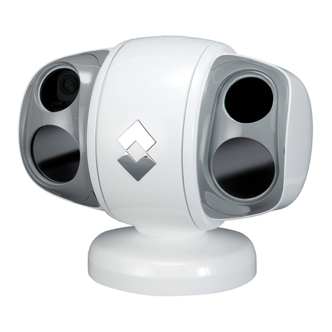
Thank you for buying your new Voyager II! This manual describes the physical mounting and electrical
connection of the Voyager II camera. If you need help during the installation process, call 888.747.3547
to speak with one of FLIR’s Applications experts. The Voyager II should be installed by a qualified marine
electronics technician, as incorrect installation could void the warranty.
The Voyager II comes with these standard components:
• Camera Body
• Bulkhead Box
• NMEA Interface Board (in a separate bag inside the Bulkhead Box)
• 50’ or 100’ main sensor cable (depending on what you ordered) - connects
the Camera Body to the Bulkhead Box
• Joystick Control Unit (JCU) with 100’ cable that connects to the Bulkhead Box
• System Power cable (10’)
• Voyager Documentation Package
You may need to supply:
• 16- gauge electrical wire; up to 100’ (3-conductor, for system power)
• Six (6) ¼-20 stainless steel bolts for attaching the Voyager II Camera Body. Note that bolt
length may be dependant on mounting platform thickness
• Four (4) bolts or screws for attaching the Bulkhead Box as required
• Miscellaneous electrical hardware, connectors and tools
If using the NMEA interface features, you will need to provide a 2-wire serial cable to the Bulkhead
Box from your NMEA device.
Installation Preparation
• Find a good place to mount the Voyager II’s components:
o Mount the Voyager II as high as practical, but without interfering with any radar,
navigational or communications electronics, and minimizing the degree to which
vessel structures block the camera’s view.
o Mount the Voyager II as close to the vessel’s centerline as possible so you will have
a symmetrical view of on-coming traffic.
o Voyager II should be mounted on a flat surface with the base on the bottom and the
camera on top. Do not hang the Voyager II upside down; the picture will display
upside down, and you may damage the Voyager II.
Prior to Cutting/Drilling Holes
• Once the mounting location has been selected, verify both
sides of the mounting surface are accessible.
• Determine if any interior trim panels must be removed in order to gain access to the
mounting hardware, and remove them ahead of time.
When selecting a mounting location for the Voyager II, consider cable lengths and routing. Ensure•
the cables are long enough, given the proposed mounting locations and cable routing require-
ments, and route the cables before you install the components.
