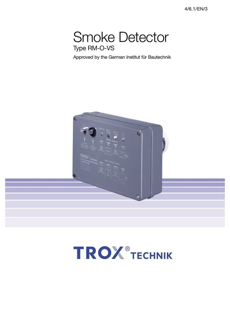
Trox RM-O-3-D Specification sheet

Operating and
installation Manual
Smoke Detector
TypeRM-O-3-D
For controlling fire and smoke protection dampers
General building inspectorate approval
Operating Instructions RM-O-3-D / Publication no. M375DD8 (08/2015)
Z-78.6-125

Operating Instructions RM-O-3-D / Publication no. M375DD8 (08/2015)2
Subject to changes / All rights reserved © TROX GmbH
Contents
TROX UK
Caxton Way,
Thetford, Norfolk, IP24 3SQ
Tel:+44(0)1842754545
Fax:+44(0)1842763051
E-Mail: service@troxuk.co.uk
www.troxuk.co.uk
1 General Information 3
Co-Applicable Documents 3
Explanation of the symbols of this manual 3
Explanation of the symbols on the smoke
detector RM-O-3-DD 3
2 Safety and Intended Use 4
General information on safety
Standards and guidelines
Repair and spare parts
Notes on environmental protection
Intended use
Prohibited use
Residual dangers
3 Product Description 5
Function description 5
Description RM-O-3-E 5
Operating status displays 6
4 Technical Data 7
5 Transport, Storage
and Packaging 7
Checking the delivery
Transportation on site
Storage
Packaging
6 Installation 8
Installation in fire damper FK-EU 8
Installation in air duct or V-part 9
7 Electrical Installation 10
230 V AC supply voltage 10
24 V DC supply voltage 10
Connection of fire / smoke damper 10
Connection of fan 10
Connection of contamination indicator 10
Connection of external reset button 10
8 Fuction Test/Commissioning 11
9 Maintenance 12
Maintenance 12
Inspection 12
Repair 12
10 Cleaning 12
Dismantling smoke detector head 12
Mounting smoke detector head
4
4
4
4
4
4
4
7
7
7
7
12

Operating Instructions RM-O-3-D / Publication no. M375DD8 (08/2015) 3
1 General Information
This operating manual describes the smoke
extraction device in the variants:
• RM-O-3-D for24V DCSupply Voltage
• RM-O-3-D for230 V ACSupply Voltage
In order to ensure the complete function of the
smoke extraction device RM-O-3-D, it is
necessary to read the instructions supplied with
the device before any use and to observe the
instructions contained therein. When the system
is handed over, the operating instructions must
be handed over to the plant operator. The system
operator must attach the operating instructions to
the system documentation.
Malfunctions or damage caused by non-
observance of this manual or by non-compliance
with legal provisions do not give rise to liability
claims against the manufacturer.
These operating instructions are intended for
planners, installers and operators of ventilation
systems into which the smoke extraction device
is to be integrated. Furthermore, the operating
instructions are directed to persons performing
the following tasks:
• Transport and storage
• Installation
• Electrical installation
• Commissioning
• Maintenance
• Cleaning
Co-Applicable Documents
In addition to these operating instructions, the
general building inspectorate approval
Z-78.6-125 must be observed.
Explanation of the symbols of
this manual
Danger!
Marking a risk to life and limb by electrical
voltage.
Note
Identification of important notes or
information.
Explanation of the symbols on the
smoke detector RM-O-3-D
Danger!
Electric shock when opening the housing
cover due to live parts.
• The housing cover may only be opened
by qualified electricians.
• Switch off the power supply before
working on the electrical equipment.

Operating Instructions RM-O-3-D / Publication no. M375DD8 (08/2015)
4
2 Safety and Intended Use
General safety information
Only qualified personnel may carry out the work
described on the smoke extraction device. Only
electricians may work on the electrical
components.
For installation, electrical connection and
maintenance, sufficient space must be provided for
unimpeded operation at the smoke extraction
device.
Standards and guidelines
During all work on the smoke extraction device
u.a. to observe the following regulations and
guidelines:
• Geräte- und Produktsicherheitsgesetz
• Ordinance on Industrial Safety
• Building regulations
• Accident Prevention Regulations (BGV A1, BGV A3)
• Maintenance standards DIN 31051 and
EN 13306
• All other relevant standards and regulations for fire
protection
Repair and replacement parts
The smoke detector RM-O-3-D is a safety
component specially developed for fire protection
in ventilation systems. To maintain the function,
only original TROX replacement parts may be
used for repair.
Notes on environmental protection
To protect the environment, please pay attention
to the following points:
• The packaging of the smoke detector must be
disposed of in an environmentally sound manner.
• The smoke detector must be properly disposed of
by an authorized body after it has been taken out of
service.
• Electronic components must be disposed of in
accordance with national electronic scrap
regulations.
Intended Use
The smoke detector RM-O-3-D is used to control
and trigger fire or smoke dampers to prevent the
transmission of fire and smoke through the air
duct.
In addition, the smoke extraction device can be
used to shut down the fan of the ventilation
system.
The fire or smoke damper must be equipped with
an electric spring return actuator or a holding
magnet or a solenoid valve.
The operation of the smoke extraction device is
only permitted under consideration of the general
and special provisions of the general building
inspectorate approval Z-78.3-125. In addition,
the installation instructions and the technical data
of these operating and assembly instructions
must be observed.
Illegal use
The smoke detector must not be used under the
following conditions:
• Use in ventilation systems of commercial
kitchens (general kitchen exhaust air)
• Use inEx-Zones.
• Outdoor use without adequate protection
against weather conditions.
• Use in ventilation systems where the function
is hindered by heavy soiling, extreme humidity
or chemical contamination
• Use in installation situations in which an
inspection, maintenance or functional test
when installed is not possible.
Changes to the smoke detector and the use of
spare parts that are not approved by TROX are
not permitted.
Residual risks
TROX smoke detectors are subject to strict quality
controls during manufacture. In addition, a
functional test is carried out before delivery.
Damage during transport or installation may impair
the function. The proper function of the smoke
detection device must be checked during
commissioning and ensured in the course of
further operation by recurring maintenance
measures.

Operating Instructions RM-O-3-D / Publication no. M375DD8 (08/2015) 5
3 Product Description
Function Description
In order to prevent the spread of smoke in buildings
through the ventilation and air conditioning
systems, it is important to detect the smoke at an
early stage.
The smoke detector RM-O-3-D is used to control
and trigger fire and smoke dampers. It works
according to the scattered-light principle and
detects the smoke independently of temperature,
so that fire dampers close even before the
triggering temperature has been reached.
In addition, can be caused by the
Rauchauslöseein-direction switching off the fan.
The closing of the fire or smoke protection
damper occurs in the case of smoke detection by
interrupting the supply voltage.
The smoke detector can be used for fire or smoke
dampers with the following triggering devices:
• Electric spring return actuator (normally
CLOSED)
• Pneumatic drive (pressureless CLOSED)
• Holding magnet
①Casing
②LED redalarm position
③LEDyellowcontamination indicator
④LED green system monitoring
⑤Button Test/Reset
⑥Smoke detector head (Order No. M536HC7)
⑦Base
⑧Slot for 24 V DC board
⑨Connection terminals 230 V AC
⑩24 V DC PCB VWM (Order No. M516EJ4)
⑤
④
③
②
①
⑦
⑥
⑨
⑧
⑩
Description RM-O-3-D

Operating Instructions RM-O-3-D / Publication no. M375DD8 (08/2015)
6
3 Product Description
Operational states
LED display operating condition Damper position
Fire / smoke
protection damper
red yellow green
alarm relay signal relay
Ready for operation
Supply voltage OK
3412
Supply voltage is missing
3412
Supply voltage OK
Electronics defective
Smoke detector is missing
–
Alarm triggering immediately -
3412
Contamination 1)
70 % .... 90%
3412
Contamination 1)
> 90%
–
Alarm triggering immediately -
3412
Test/Reset
–
inspection –
3412
Smoke detection 2)
– Alarm triggering immediately -
3412
LED on
LED off
LED blinking
1) Contamination indicator
up to 70% – Normal range
> 70 % ... 90% – Warning
> 90% – Alarm
2)The alarm position triggered by smoke (event or
maintenance) can only be canceled by pressing the
push button after the smoke detector is smoke free
again.

Operating Instructions RM-O-3-D / Publication no. M375DD8 (08/2015) 7
4 Technical Data
RM-O-3-D
EMC immunity to EN 61000-6-1,
EN 61000-6-2,
EN 61000-6-3,
EN 61000-6-4
Supply voltage 230 V AC + 10 / – 15 %
50/60 Hz
oder
24 V DC ± 6 %
Power consumption 3 VA
Fuse T 100 L 250 V
Protection IP 42
Ambient temperature 0 °C … + 60 °C
Permissible air
speed
1 m/s ... 20 m/s
Permissible
humidity
≤95%RH,non-
condensing
Warning increased
contamination
> 70 %
System monitoring • > 90 % contamination
• Smoke detector is
missing
• Data not transmitting
Alarm relay
contact (trip,
contamination)
250 V 2 A
24 V DC 100 W
Mass 0,7 kg
5 Transport, Storage
and Packaging
Check the delivery
Check delivery immediately after delivery for
transport damage and completeness. In the case
of transport damage or incomplete delivery,
inform the freight forwarder and the supplier
immediately.
Complete delivery includes:
• Smoke detector RM-O-3-D
• Operating and installation manual
Transporting on the construction site
If necessary, transport the smoke detector to the
point of installation in the shipping container.
Storage
For interim storage observe the following points:
• Remove the foil from the shipping box.
• Protect the smoke detector from dust and dirt.
• Protect from moisture and direct sunlight.
• Do not expose the smoke detector (also
packed) directly to the weather.
• Do not store the smoke detector below - 40 ° C
and above 50 ° C.
Packaging
Dispose of packaging material properly
after unpacking.

Operating Instructions RM-O-3-D / Publication no. M375DD8 (08/2015)
8
6 Installation
Installation in fire damper FK-EU
The smoke extractor RM-O-3-D can be installed
in the inspection opening of fire dampers of the
FK-EU series. When doing so, observe the
installation location, see illustration on the right.
When using the FK-EU as overflow flap, in
accordance with the building inspectorate
approval Z-6.50-2031: install the smoke detector
RM-O-3-D in the upper inspection opening of the
fire damper.
Assembly sequence::
1. Place adapter ③ on inspection cover ② and
screw it to the housing of the fire damper with
self-tapping screws ((inspection cover serves
for centering).
2. Unscrew and remove inspection cover.
3. Insert the smoke detector RM-O-3-D ① into
the inspection opening and secure it to the
adapter with knurled nuts ⑤.
4. Connect the fire damper electrically to the
smoke detector, see "Electrical installation"
on page 10.
Note:
Older fire dampers of the FK-K90 and FK-EU
series may have a metal inspection cover.
In this case, the inspection cover can be
disassembled and the smoke extraction device
with the washers and wing nuts without adapters
mounted directly on the fire damper.
①Smoke detectorRM-O-3-D
②Inspection cover BSK (plastic)
③Adapter RM-O-3-D, order no.
Galvanized: A00000043410
Stainless steel: A00000043411
④ Tapping screws (4 pieces)
⑤ Knurled nuts (3 pieces)
①
③
④②
⑤
Installation in FK-EU
H 200 – 320 H 200 – 800
Installation location depending on the
height H

Operating Instructions RM-O-3-D / Publication no. M375DD8 (08/2015) 9
6 Einbau
Installation in Air Duct
The smoke extractor RM-O-3-D is installed in
the following procedure:
Note
For proper function, it must be ensured
that the smoke detector head is
constantly traversed by air. This results
in the following recommendations:
• Minimum distance of 1.5 × H between
smoke extraction device and bends,
controllers, etc.
• Install the smoke detector in the upper
third of the air duct (not in the corner
area).
• Install the smoke detector in the
direction of the air in front of the fire
or smoke damper.
1. Determine installation location and
attach sticker ①.
2. Make a hole for the smoke detector head of
the smoke detector.
3. Pre-drill holes for tapping screws.
4. Insert the smoke detector RM-O-3-D ②
into the hole 3 Secure the self-tapping
screws ③.
5. Connect the fire damper electrically to the
smoke detector, see "Electrical installation"
on page 10.
①Sticker
②Smoke detector RM-O-3-D
③Sheet metal screw 3 pieces, by others
Installation in Air Duct
① ② ③
Rauchauslöseeinrichtung
Auslösung / relase
Verschmutzung / pollution
Betrieb / operation
Test / Reset
Typ RM-O-3-D
A
A
Ø100
Ø140
Ø180
Ø160
~ 40~ 95
Ø7
23
Ø13
Dimensions

Operating Instructions RM-O-3-D / Publication no. M375DD8 (08/2015)10
7 Electrical Installation
L1 1 2 3 4 1 2NL1 N PE PE
L1 L2 L3
– + S1 S2 S3 S4 S5 S6
5–250 V
AC / DC
N(–) L(+)
PE N L
230 V AC
①
② ③
⑤
④
⑥
⑦N L
230 V AC Supply Voltage
Danger!
Electric shock when touching live parts.
Electrical equipment is under dangerous
electrical voltage.
• Only electricians may work on the
electrical components.
• Switch off the power supply before
working on the electrical equipment.
When connecting, observe the VDE guidelines
and local power supply company regulations!
The state regulations, in accordance with the
"Directive on fire protection requirements for piping
systems" in the currently valid version, must be
observed.
Supply voltage 230 V AC
Terminal strip L1, terminal L1 / N / PE
Connection is made on the basis of the adjacent
connection example.
Install the strain relief of the connection cable on
site.
Supply voltage 24 V DC
Terminal strip L4, terminal + / -
Connection is made using the connection
example on page 11.
The connection with 24 V DC may only be made
via the optionally available connection board
VWM (Order No. M516EJ4), as this causes
tripping in the event of impermissible voltage
fluctuations. Install the strain relief of the
connection cable on site.
Connection of fire / smoke damper
Terminal strip L2, terminal 3/4
In the range of permissible switching capacity
(see page 7) several fire or smoke dampers can
be connected in parallel.
Connection fan
Terminal strip L2, terminal 3/4
In the range of the permissible switching
capacity (see page 7), the fan can also be
switched off via the smoke release device. For
higher switching power, auxiliary relays must be
used.
Connection contamination indicator
Terminal strip L2, terminal 1 - 2
In the range of the permissible switching
capacity (see page 7), relays or indicator lights
can be switched or the forwarding to the fire
alarm technology implemented.
Connection of external reset button
Terminal strip L3, terminal 1 - 2

Operating Instructions RM-O-3-D / Publication no. M375DD8 (08/2015) 11
7 Electrical Installation 8 Functional Test/
Commissioning
A functional test shall be carried out before
commissioning, thereafter annually and after
modifications, e.g. Repair.
Without Smoke
Press the "Reset / Test" button on the smoke
extraction device or in the control panel (optional).
The circuit to the located on the fire or smoke-
protection shutter release device is interrupted;
the fire or smoke damper closes.
After relieving the button, fire and smoke
protection flaps with spring return drive or
pneumatic drive automatically move to the OPEN
position.
Note
Fire dampers with magnetic release
devices can only be opened manually on
site.
With Smoke
Spray the test gas through an opening in the
immediate vicinity of the smoke extraction device
into the air line (on-site testing). If the threshold
value (fire characteristic smoke) is exceeded, the
circuit for the extinguishing device located in the
fire or smoke damper is interrupted; the fire or
smoke damper closes.
To open - after the smoke detector is again smoke
free - press the "Test / Reset" button on the smoke
triggering device.
After relieving the button, fire and smoke
protection flaps with spring return drive or
pneumatic drive automatically move to the OPEN
position.
Note
Fire dampers with magnetic release
devices can only be opened manually on
site.
All operating, warning and alarm functions are
described on page 4.
24 V DC Supply Voltage
L1 1 2 3 4 1 2NL1 N PE PE
L1 L2 L3
– + S1 S2 S3 S4 S5 S6
5–250 V
AC / DC
+ – + –
24 V DC
L4
N(–) L(+)
– +
①
② ③
⑤
④
⑥
⑦
①Smoke detectorRM-O-3-D
②External contamination indicator
(by others)
③External button "Test / Reset"
④Triggering device fire / smoke
protection damper
⑤Damper position display CLOSED
⑥Damper position display OPEN
⑦Further tripping device or fan

Operating Instructions RM-O-3-D / Publication no. M375DD8 (08/2015)
12
9 Maintenance
Danger!
Electric shock when touching live parts.
Electrical equipment is under dangerous
electrical voltage.
• For cleaning, the housing must not be
opened.
• Do not use any liquids near the smoke
detector.
If it is dirty> 70% (yellow LED lit), the smoke
detector head should be cleaned.
• Cleaning the smoke detector by blowing it out
with oil and water-free compressed air.
If this measure is unsuccessful, the smoke
detector head must be replaced (Order No.
M536HC7).
• Removing contaminants on the strainer screens
for the air inlets.
Dismantling Smoke Detector Head
• Dismantle smoke extraction device ① from the
air duct.
• Turn smoke detector head ② counterclockwise
until the smoke detector head disengages.
• Remove smoke detector head from socket ③.
Mounting Smoke Detector Head
• Place smoke detector head ② on base ③.
• Turn the smoke detection head on the base until the
smoke detection head engages in the base.
• Turn the smoke detector head clockwise until the
smoke detector head clicks into place.
Note
After installation of the smoke detection
head, a functional test must be carried out.
①
②
③
Danger!
Electric shock when touching live parts.
Electrical equipment is under dangerous
electrical voltage.
• Only electricians may work on the
electrical components.
• Switch off the power supply before
working on the electrical equipment
Regular care and maintenance ensures the
operational readiness, operational safety and
service life of the smoke extraction device.
Maintenance is carried out in accordance with EN
13306 in conjunction with DIN 31051.
The maintenance is the responsibility of the
operator of the plant. The operator is responsible
for setting up a maintenance plan with the
definition of maintenance objectives and
functional safety with its maintenance
management.
Maintenance
The smoke detector RM-O-3-D and the drive-up
aid are maintenance-free with regard to wear.
Inspection
Before the first commissioning and after changes,
the smoke extraction device must be inspected.
Thereafter, the functional reliability of the smoke
evacuation device is to be checked at least once a
year. In addition, the state or building regulations
must be observed.
The test of each smoke extraction device must be
documented and evaluated. In the event of
deviations from the nominal condition, suitable
repair measures must be taken.
Repair
For safety reasons, repair work that influences the
fire protection may only be carried out by qualified
personnel or by the manufacturer. For repair only
original spare parts may be used. After a repair, a
functional test must be carried out, see "Function
test / commissioning" on page 11..
10 Cleaning
Table of contents
Other Trox Smoke Alarm manuals
Popular Smoke Alarm manuals by other brands
Vermont Castings
Vermont Castings Signature VC3624GS Assembly and owner's manual
Kidde
Kidde P4010ACSAQ-WF user guide

Innogy
Innogy WSD-2.0 manual

Honeywell
Honeywell 5800COMBO Installation and setup guide

FireAngel
FireAngel Thermoptek ST-622 user manual

Resolution Products
Resolution Products RE612 CryptiX quick start guide
