manuals.online logo
Brands
  1. Home
  2. •
  3. Brands
  4. •
  5. Troy-Bilt
  6. •
  7. Tiller
  8. •
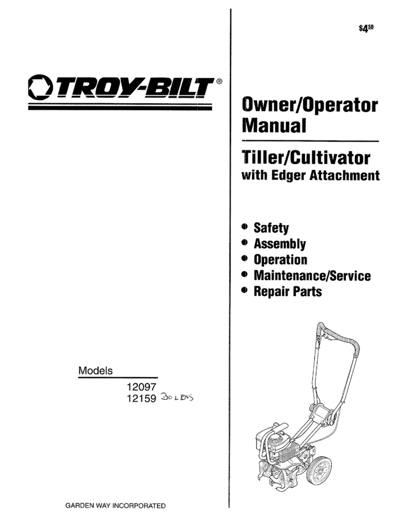
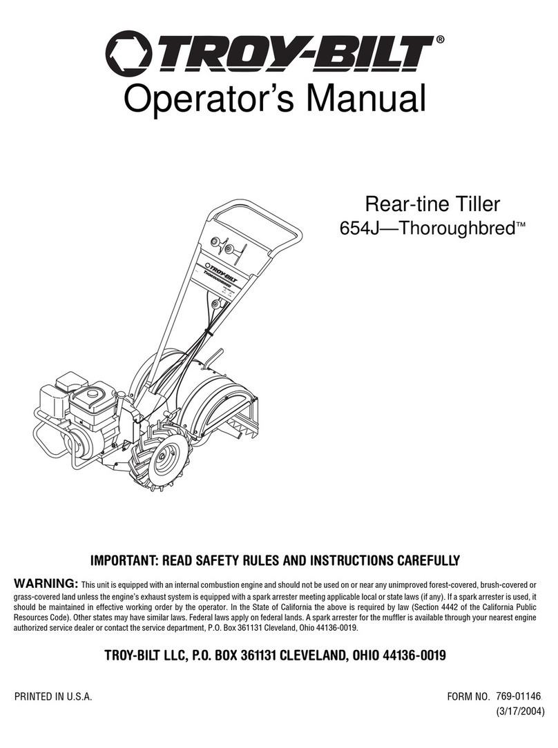
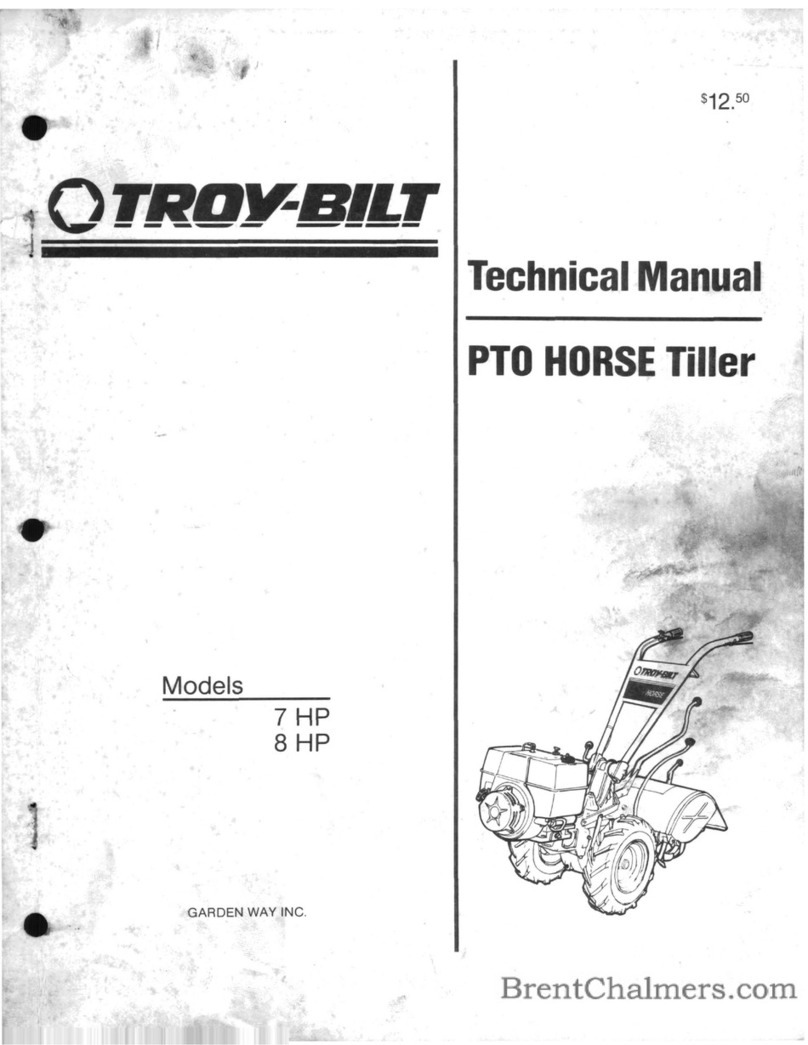
  9. Troy-Bilt Horse E682L User manual

Troy-Bilt Horse E682L User manual

This manual suits for next models

2

Other Troy-Bilt Tiller manuals

Troy-Bilt Pony 12211 User manual

Troy-Bilt

Troy-Bilt Pony 12211 User manual

Troy-Bilt PONY User manual

Troy-Bilt

Troy-Bilt PONY User manual

Troy-Bilt 634K--ProLine User manual

Troy-Bilt

Troy-Bilt 634K--ProLine User manual

Troy-Bilt 644H-Bronco, 645A-Bronco User manual

Troy-Bilt

Troy-Bilt 644H-Bronco, 645A-Bronco User manual

Troy-Bilt 664D-Pony User manual

Troy-Bilt

Troy-Bilt 664D-Pony User manual

Troy-Bilt 664D-Pony User manual

Troy-Bilt

Troy-Bilt 664D-Pony User manual

Troy-Bilt Garden Way 12194 User manual

Troy-Bilt

Troy-Bilt Garden Way 12194 User manual

Troy-Bilt 4-Cycle User manual

Troy-Bilt

Troy-Bilt 4-Cycle User manual

Troy-Bilt 643C Tuffy/Bronco User manual

Troy-Bilt

Troy-Bilt 643C Tuffy/Bronco User manual

Troy-Bilt PRO LINE 644HMBRONCO User manual

Troy-Bilt

Troy-Bilt PRO LINE 644HMBRONCO User manual

Troy-Bilt 682J-Horse User manual

Troy-Bilt

Troy-Bilt 682J-Horse User manual

Troy-Bilt 12088 User manual

Troy-Bilt

Troy-Bilt 12088 User manual

Troy-Bilt 148H User manual

Troy-Bilt

Troy-Bilt 148H User manual

Troy-Bilt 12087 Owner's manual

Troy-Bilt

Troy-Bilt 12087 Owner's manual

Troy-Bilt 7HP Pony 12211 User manual

Troy-Bilt

Troy-Bilt 7HP Pony 12211 User manual

Troy-Bilt OEM-290-260 User manual

Troy-Bilt

Troy-Bilt OEM-290-260 User manual

Troy-Bilt 630C-Tuffy User manual

Troy-Bilt

Troy-Bilt 630C-Tuffy User manual

Troy-Bilt Colt FT User manual

Troy-Bilt

Troy-Bilt Colt FT User manual

Troy-Bilt Econo-Horse 12185 User manual

Troy-Bilt

Troy-Bilt Econo-Horse 12185 User manual

Troy-Bilt 769-03618 User manual

Troy-Bilt

Troy-Bilt 769-03618 User manual

Troy-Bilt 12159 Owner's manual

Troy-Bilt

Troy-Bilt 12159 Owner's manual

Troy-Bilt PTO Horse User manual

Troy-Bilt

Troy-Bilt PTO Horse User manual

Troy-Bilt 12087 Owner's manual

Troy-Bilt

Troy-Bilt 12087 Owner's manual

Troy-Bilt Horse 682J User manual

Troy-Bilt

Troy-Bilt Horse 682J User manual

Popular Tiller manuals by other brands

WIL-RICH 2500 Operator's manual

WIL-RICH

WIL-RICH 2500 Operator's manual

MTD 410R parts list

MTD

MTD 410R parts list

Viking HB 685 instruction manual

Viking

Viking HB 685 instruction manual

SMASH TLG415 instruction manual

SMASH

SMASH TLG415 instruction manual

FarmBoy FB-IC-209P user manual

FarmBoy

FarmBoy FB-IC-209P user manual

Craftsman 247.29931 Operator's manual

Craftsman

Craftsman 247.29931 Operator's manual

MTD FRT Series Operator's manual

MTD

MTD FRT Series Operator's manual

Craftsman 917.298353 owner's manual

Craftsman

Craftsman 917.298353 owner's manual

MTD OHV Series Original operating instructions

MTD

MTD OHV Series Original operating instructions

YAT YT5601-01 Assembly, Use, Maintenance Manual

YAT

YAT YT5601-01 Assembly, Use, Maintenance Manual

Craftsman 917.296010 owner's manual

Craftsman

Craftsman 917.296010 owner's manual

Scheppach MTP560 Translation from the original instruction manual

Scheppach

Scheppach MTP560 Translation from the original instruction manual

GARDEN WAY 12194 owner's manual

GARDEN WAY

GARDEN WAY 12194 owner's manual

Classen STAND-AER SA-25 Operator's manual and parts list

Classen

Classen STAND-AER SA-25 Operator's manual and parts list

Altrad ATIKA BH 1400 N Original instructions, safety instructions, spare parts

Altrad

Altrad ATIKA BH 1400 N Original instructions, safety instructions, spare parts

DR PILOT 2 Safety & Operating Instructions

DR

DR PILOT 2 Safety & Operating Instructions

AL-KO TL 1820 Instructions for use

AL-KO

AL-KO TL 1820 Instructions for use

breviglieri mekfarmer 120 Operating and maintenance

breviglieri

breviglieri mekfarmer 120 Operating and maintenance

manuals.online logo
manuals.online logoBrands
  • About & Mission
  • Contact us
  • Privacy Policy
  • Terms and Conditions

Copyright 2025 Manuals.Online. All Rights Reserved.

0TRO- ] BIIT°
m m _iiiiiiiiiiiiiiii1_ _111111111111_1111_
Ope S a ual
Rear-finePTO TillerModels
Model 682J Shown
iMPORTANT:READ SAFETY RULES AND iNSTRUCTiONS CAREFULLY
Warning: This unit is equipped with an internal combustion engine and should not be used on or near any unimproved forest-covered, brush-
covered or grass-covered land unless the engine's exhaust system is equipped with a spark arrester meeting applicable local or state laws (if any).
If a spark attester is used, it should be maintained in effective working order by the operator. In the State of California the above is required by law
(Section 4442 of the California Public Resources Code). Other states may have similar laws. Federal laws apply on federal lands. A spark arrester
for the muffler is available by contacting the service department at Troy-Bilt LLC, P.O. Box 36113! Cleveland, Ohio 44136-0019.
TROY-BJLT LLC, P.O. BOX 361131, CLEVELAND, OH 44136-0019
PRINTED IN USA FORM NO. 770-10598D
(10/15/2004)
TABLE8F CONTENTS
Content Page
CaNing Customer Support .................................................... 2
Safety ................................................................... 3
AssemMy ................................................................. 6
Features and Controls ....................................................... 11
Operation ................................................................ 14
Maintenance .............................................................. 28
Troubleshooting ........................................................... 41
Attachments & Accessories .................................................. 43
Parts List ................................................................. 44
Warrany Unformation ........................................................ Back Cover
FJNDJN6MODELNgMBER
This Operator's ManuaUis an important part of your new Rear°tine THUer,UtwHUheUpyou assemMe, prepare and
maintain the unit for best performance, PUease read and understand what it says,
Before you start assembling your new equipment, please locate the model plate on the equipment and copy the infer°
mation from it in the space provided below, This information is very important if you need help from our Customer
Support Department or an authorized dealer,
You can locate the model number by looking at the rear surface of the tine shield. A sample model plate is
explained below. For future reference, please copy the model number and the serial number of the equipment
in the space below
0 TRO_r'_X_,,T" TROY-[}mLT LLC
P. O. BOX 361131
www.troybilt.com CLEVELAND, ON 44136
338=558=7228
896 =8,48 =6483
Copy Model Number Here
Copy Serial Number Here
ENGINEJNFSRMATJON
The engine manufacturer is responsible for all engine-related issues with regards to performance, power-rating, speci°
fications, warranty and service, Please refer to the engine manufacturer's Owner's/Operator's Manual packed sepa-
rately with your unit for more information,
CP,LLJNGCUSTOMERSgPPS}{T
If you have difficulty assembling this product or have any questions regarding the controls, operation or maintenance
of this unit, please call the Customer Support Department.
Call 1- (330) 558-7220 or 1- (868) 840-6483 to reach a Customer Support representative, Please have
your unit's model number and serial number ready when you call, See previous section to locate this
information, You will be asked to enter the serial number in order to process your call,
n
Safe_yAmertSymbem
,_ This is a safety alertsymboI_ It is used in this
manuaiand on the unit to alert youto
potential hazards. Whenyou seethis symbol,
readand obeythe messagethat foliows it.
Failureto obeysafety messagescould result in personal
injury or property damage.
This machine meets voluntary safety standard B71,8
- 1996, which is sponsored by the Outdoor Power
Equipment Unstitute, Unc,, and is pubfished by the
American NationaUStandards Unstitute,
A
Theengine exhaust from this productcontains
chemicalsknownto the State of California to cause
cancer,birth defectsor other reproductive harm.
1. Carefuilyreadthis Owner'sManual, the
separateEngineOwner's Manual,and any
other literature you may receive.Bethor-
oughiy famiiiar with the controis and the
proper useof the tiiier and its engine.
Know howto stop the unit and disengage
the controls quickiy.
2. Neveraliow chiidren to operatethe
tiller. Neverallow adults to operatethe
tilier without proper instruction.
3. Keepthe areaof operation clearof aii
persons, particularly chiidren and pets.
4. Keepin mindthat the operator or user
is responsible for accidents or hazards
occurring to other people,their property,
andthemselves.
1. Thoroughly inspect the areawherethe
tiiier isto be usedand removealIforeign
objects.
2. Putthe Wheelsfrines/PTO Drive Lever
into NEUTRALbeforestarting the engine.
3. Do not operatethe tiiier without
wearingadequateoutergarments. Avoid
loose garmentsor jewelry that coutd get
caught in moving parts.
4. Do not operatethe tiiier when barefoot
or wearingsandals,sneakers,or iight
footwear. Wear protective footwearthat
wiii improve footing on siippepysurfaces.
5. Do nottiii near underground electric
canes, teiephoneiines, pipes or Iloses. If
in doubt, contact your telephoneor utility
company.
6. Warning: Handlefue!with care;it is
highly fiammabie and its vapors are
expiosive. Besureto takethe following
precautions:
a. Storerue! in containers specifically
designedfor this purpose.
b. The gascapshaii never be removed
or rue!addedwhiie the engine is
running. Ailow the engineto cooi
for severalminutes before adding
fuel.
¢. Keepmatches,cigarettes, cigars,
pipes, openflames, and sparks
away from the fueitank and fueI
container.
&Fiii fuei tank outdoors with extreme
care. Neverfill fueI tank indoors.
Usea funnel or spout to prevent
spiiiage.
e. Repiaceaii rue!tank and container
caps securely.
f. If fuel isspiiied, do not attempt to
start the engine, but movethe
machineaway from the areaof
spiiiage and avoidcreating any
source of ignition until fuel vapors
havedissipated.
7. Nevermakeadjustments whenengine
is running (unless recommendedby
manufacturer).
1. Donot put hands orfeet nearor under
rotating parts. Donot aiiow handsor any
other part ofthe body or ciothing nearthe
rotating tines or nearany other moving
part. Thetines beginto rotate forward
oncethe engine starts, the Tines/PTO
Clutch Leveris in the ENGAGEposition,
the Forward Interlock Leversare squeezed
closed and the Wheelsfrines/PTO Drive
Leveris shifted to FORWARD.Thetines
rotate in Reversewhether the Interlock
Leversare ciosed or open.
2. Exerciseextremecaution when on or
crossing graveldrives, walks, or roads.
Stayalert for hidden hazardsor traffic. Do
not carry passengers.
3. After striking a foreign object, stop the
engine, removethe wire from thespark
piug wire and prevent it from touching the
spark piug. ThorougNy inspectthe
machinefor any damageand repair the
damagebefore restarting and operating
the machine.
4. Exercisecaution to avoid slipping or
falling.
5. If the unit should start to vibrate abhor-
marly,stop the engine,disconnect the
spark piug wire and prevent it from
touching the spark piug, and check imme-
diatelyfor the cause.Vibration is
generaiiya warning of trouble.
6. Stopti_eengine,disconnect the spark
piug wire and prevent it from touching the
spark piug wheneveryou ieavethe
operatingposition, before uncloggingthe
tines, or when making any repairs, adjust-
ments or inspections.
7. Takeali possible precautionswhen
leavingmachine unattended.Stopengine.
Disconnectspark plug wire and move it
away from spark piug. Removeignition
key on electdcstart models
Section1: Safety
8. Beforecleaning, repairing, or inspect=
ing, stop the engineand makecertain atI
moving parts havestopped. Disconnect
the spark piug wire and prevent it from
touching the spark piug to prevent acci=
dentaIstarting.
9. The flap on thetine hood must be
down when operatingthe tiiier, unless
using the Hiiier/Furrower attachment.
10. Neverusethe tiiier unless proper
guards, piates,or other safety protective
devicesare in place.
11. Do not run engine in an enclosed
area.Engineexhaustcontains carbon
monoxide gas, a deadlypoison that is
odorless, coloriess, and tasteless.
12. Keepchildren and pets away.
13. Neveroperatethetiiier underengine
power if the WheeISpeedLeveris in the
FREEWHEELposition. In FREEWHEEL,
the wheels wiii not hold thetiiier backand
the revoiving tines could propei the tiiier
rapidly, possibty causing ioss of controi.
AIwaysengagethe WheetSpeedLeverin
either FASTor SLOWposition before
starting the engine or engaging thetines
with the WheeIs/Tines/PTODrive Lever.
14. Be aware that the tiller may unexo
pectedlv bounce upward or jamp
forward ifthe tines should strike
extremely hard packed soil, frozen
ground, or buried obstacles like large
stones, roots, or stumps, ff in doubt
about the tilling conditions,always use
the following operating precautions to
assist you in maintaining control of the
tiller:
a. Walk behind and to one side of the
tiller, using one handon the han-
dlebars. Relax your arm, bnt rise a
secnre handgrip.
b. Use shallower depth regulator
settings, working gradually deeper
with each pass.
c. Use slower wheel, tine and engine
speeds.
d. Clear the tilling area of all large
stones, roots and other debris.
e. Avoid using downward pressureon
handlebars.If need be, use slight
npward pressure to keepthe tines
from digging too deeply.
f. Before contacting hardpacked soil
at the end of a row, reduce engine
speed and lift handlebarsto raise
tines out of the soil.
g. Jnan emergency, stop tines and
wheets byshifting the
WheelsiTinesiPTO Drive Lever
intoNEUTRAL.tf you can not
reach the lever or havelostcontrom
of the tiller, let go of the handle=
bars and aHcontroms,go not
attempt to restrain the tiller.
15. Donot overioadthe tiiier's capacity by
attempting to till too deeplyat too fast a
rate.
16. Neveroperatethe tiller athigh
transport speedson hard or slippery
surfaces. Look behind and usecarewhen
backing up.
t7. Donot operatethetiiier on a slope
that istoo steep for safety. Whenon
slopes, slow down and makesure you
havegood footing. Neverpermit the tiiier
to freewheel down slopes.
18. Neverallow bystanders near the unit.
19. Only useattachmentsand accessories
that areapproved bythe manufacturer of
the tiller.
28. Usetiiier attachments and acces-
sories when recommended.
21. Neveroperatethe tiller without good
visibility or iight.
22. Neveroperatethe tiiier if you are
tired, or under the influence of alcohol,
drugs or medication.
23. Operatorsshali not tamper with the
engine-governor settings on the machine;
the governor controis the maximum safe
operatingspeedto protect the engineand
ali moving parts from damagecausedby
overspeed. Authorized serviceshail be
sought if a problemexists.
24. Donot touch engineparts which may
behot from operation. Letparts cool
downsufficiently.
25. POBON/OANGER--CAUSES
SEVEREBURNS.Thebattery on electric
start models contains suifudc acid. Avoid
contact with skin, eyesor clothing. Keep
out of reachof children.
Antidotes:
External- Flushimmediately with lots of
water.
Internal- Drink largequantities of water
or milk. Follow with milk of magnesia,
beateneggs or vegetableoil. Calla
doctor immediately.
Eyes- Fiushwith water for 15 minutes.
Getprompt medicai attention.
26. DANGER=BATTERIESPRODUCE
EXPLOSIVEGASES. Keepsparks, flame
or smoking materiaisaway. Ventilate
whencharging battery or using in an
enctosedspace. Alwayswear safety
goggteswhen working near battery.
27. Pieaseremember:You canalways
stop thetines and wheels by releasingati
controis, or by moving the ignition switch
and/orthrottle control leveron the engine
to OFFor STOP.
28. To ioad or unload thetiller, seethe
instructions in Section4 of this Manual.
29. Useextremecaution when backing or
puliing the machinetowards you.
30. Startthe engine carefuiiy according to
instructions and with feet well awayfrom
the tines.
31. Neverpick up or carry a machine
whiiethe engine is running.
32. Whenioading or unioadingthe tiller,
alwaysdisengagetines and usesiower
wheeland enginethrottle speeds. Use
sturdy ramps wideand strong enough to
easiiysupport the tiiier (280-to-325 ibs.
dependingon model) and operator.
Nevergo down ramps in FORWARD
drive--the tiiier couid tip forward,
exposingyou to the tines (which should
be disengaged). Always useREVERSE
driveand backdown ramps. Togo up
ramps, useFORWARDdrive and follow
the tiller.
33, The Forward Interlock SafetySystem
should betested for correct functioning
everytime the tiller or PTOpower unit is
used. SeeSection 4 in this Manual.
34. If using the optional Dozer Blade,
either removethe tine attachment, or
disengagethetines with the Tines/PTO
CiutchLever. Revolvingtines are
dangerous.
Section1: Safety
Maintenance and Sterage
1. Keepthetiiier, attachments and acces-
sories in safe working condition.
2. Checkali nuts, boits, and screws at
frequent intervalsfor proper tightness to
be surethe equipment is in safe working
condition.
3. Neverstore the tiiier with fue! in the
fueJtank insidea buiiding where ignition
sources are presentsuch ashot water
and space heaters,furnaces, ciothes
dryers, stoves,electric motors, etc.).
Aiiow engine to cool beforestoring in any
encJosure.
4. To reducethe chancesof a fire hazard,
keepthe engine freeof grass, leaves,or
excessivegrease.
5. Storegasoiine in a cooi, weJi-ventiiated
area,safetyaway from any spark- or
flame-producing equipment. Store
gasolinein anapprovedcontainer, safeiy
awayfrom the reachof chiidren.
6. Referto the Maintenancesections of
this Manuaiandthe separate Engine
Owner's Manualfor instructions if the
tiller is to be stored for an extended
period.
7. Neverperform maintenancewhiiethe
engine is running or the spark piug wire is
connected,exceptwhen specifically
instructed to do so.
8, If the fueltank hasto be drained, do
this outdoors.
Decals
Foryour safetyand the safety of others,
various safety and operationaldecalsare
located on your unit (Figure1).
Keepthe decalscleanand legibleat all
times. Contactyour Iocai servicedealer
or the Factoryfor repiacementsif any
decals are damagedor missing.
Referto the Parts List for decallocations,
descriptions and part numbers.
F) EngineStabiHzaNan.
Tapaffuemtank. B) WARNmNG:EngineIgMNan.
Emectricstartmadamsamy.
Figure 1: Location of Safety and Operating Decals.
(Briggs & Stratten engine shown)
Operating Symbols
Varioussymbols (shown here,with word
descriptions)areusedonthetillerandengine=
Yourunitmaynothaveaiiofthesymbols=
@ H I÷1
CHOKE CHOKE ROTATING
FAST SLOW STOP ON OFF TmNES
TO AVOID SERIOUS INJURY:
oDEADTHEOWNER'SMANUAL,
KNOW LOCATmONSAND FUNCTmONSOFALLCONTROLS.
oKEEPALLSAFETYDEVICESAND SHmELDSINPLACEAND WORKmNG.
NEVERALLOW CHmLDRENOR UNBNSTRUCTEDADULTSTO OPERATETILLED.
*SHUT OFFENGINEAND DmSCONNECTSPARKPLUGWIREBEFOREMANUALLYUNCLOG=
GiNGTINESOR MAKINGREPAIRS.
- KEEPBYSTANDERSAWAYFROMMACHINE.
*KEEPAWAY FROM ROTATmNGPARTS.
USE EXTREMECAUTmONWHEN REVERSINGOR PULLINGTHE MACHINETOWARDS YOU.
n
To preventpersonal injury or property
damage, do net start the engine until
all assembly steps are complete and
you have read and understand the
safety and operatinginstructionsin this
manual.
introduction
Carefuliyfoiiow these assembIystepsto
correctly prepareyour tiiier for use. It is
recommendedthat you readthis Section
in its entirety beforebeginning assembly.
NOTE:Threedifferent Norse modeltiiiers
are covered in this Manual.Use onlythe
information applicableto your model.
Tiiier enginesvary by model.Your engine
mayappear differently than those found
in illustrations of this manual.
inspect Unit
h_spectthe unit and carton for damage
immediately after deiivery. Contactthe
carrier (trucking company) if you find or
suspect damage. Inform them ofthe
damageand request instructions for fiiing
a claim. To protect your rights, putyour
ciaim in writing and maiIa copy to the
carrier within 15 days after the unit has
been delivered.Contact us atthe Factory
if you needassistancein this matter.
STEP1: Unpacking Jnstructiens
NOTE:Donot severelybend any ofthe
control cableson the unit.
1. Thetiiier is heavy. Donot attempt to
removeit from the shipping piatform until
instructed to do so in these Assembly
steps.
2. RemoveatI unassembtedparts from
the carton. Thehardwarebag is included
in your literature packaging.
3. Checkthat you havethe items iisted
below (contact your local dealeror the
Factoryif anyitems are missing or
damaged).
NOTE: Usethe screw iengthtemplate
(Figure2-1) to identify screws.
LoosePartsList
Qty. Description
1 HandlebarAssembly
1 Wheels/TinesPTODrive Lever
Thefor'towingitems
are in thehardwarebag:
1 26 oz. BottteSAE30W Oil
1 Clutch PawiSpring
1 BeltAdjusting TooI
2 PiasticCabieTies
1 Curved HeadScrew, 1/4-20 x 2
1 FlangedLock Nut, 1/4-20
1 PanHeadScrew,#10-32 x 1/2
The following parts (electric start models
only), packagedseparately.
2 Nuts, 1/4-20
(for batteryterminals)
2 Screws, 1/4-20x5/8
(for batteryterminais)
2 Keys
(in ignition switch)
NOTE:LEFTand RIGHTsides of the
tiller are as viewed from the
operator's position behind the han-
dlebars (unless otherwise noted).
Teols/J_ateriaJs Needed
for Aosembly
(1) 3/8" open-endwrench*
(2) 7/16" open-endwrench*
(2) 1/2" open-endwrench*
(1) 9/16" open-endwrench*
(1) 3/4" open-endwrench*
(1) Fiatblade screwdriver
(1) Scissors (to trim plastic ties)
(1) Tire pressure gauge
(1) 4-1/2" high wood block to prop unit
*Adjustable wrenchesmay be used.
Figure 2-1: Toidentify length of screw,
place screw on templateas shown and
measure distance between bottom of screw
head andtip of screw.
STEP2: Attach Nandiebar
JNJPORTANT: When disassembling
handlebar assembly, keep ieft-side clamp
and ratchet separated from the right-side
clamp and ratchet.
1. Disassemblethe handlebarassembly.
To do this, removethe heightadjustment
leverbyturning the ieverin a counter-
clockwise direction (Figure2-2).
2. Placethe handlebarends on either side
ofthe base,with the wire harnesstoward
the rearof the base(Figure2-2).
3. Instalithe heightadjustment iever
through the rigirt-side clamp, handlebar
end, ratchet,and base;then out through
the ieft-side ratchet, handlebarend,and
ciamp (Figure2-2). Securewith nut, but
don't fully tighten.
J_IPORTANT:Donot force the height
adjustment ieverthrouglr the handlebars.
The interlock wires may be blocking the
Section2: Assembly
leverand could be damaged.You may
gently movethe wires asideif this
condition occurs.
4. Raisehandlebarsto one of two height
settings andtighten the height adjustment
lever. Also, makesureali other mounting
hardware issecurelytightened.
Left-Side
Figure 2=3. Fully assembled handle=
bars.
Height
Adjustment Bass
Lsvsr BeJr
FRONT
OFT&LEfl ....
Wits
Harness
NOTE:Fully assembledhandlebar
assembly sllould appearasshown in
Figure2=3.
STEP3: MeveTiller 8ff Shippin9
Piatferm
1, Setthe DepthRegulator Lever
(A, Figure2-4) to Travel position. Dothis
by lifting the tiiier bythe handlebars,then
puliing straight back on the ieverand
siiding down to the highest notched
setting.
2. Setthe WheelSpeed Lever(B, Figure
2=4)to Freewheelposition. To do this,
movethe ieverapproximately halfway
betweenthe Fastand Slow settings whiie
you rockthe tiiier forward and backward
untilthe wheels movefreely.
3. Lift Handlebarshigh enough to clear
tiiier tines and pull back firmly to disiodge
the tiller from the piatform wheel wells.
STEP4: Cenneet Ferward
interlock Wire Harness
1. Removeany dirt from the Forward
Interlock wire harness plug (C, Figure
2-5) and its receptacle(D).
2, Connectthe ForwardInterlock wire
harness plug (C, Figure2-5) to the recepo
tacie (D).
STEP5: Attach
Wheels/Tines/PT8 grive Lever
Figure 2-2. Handlebar assembly.
Figure2-4: Photo shows the Depth
Regulator Lever (A) and the Wheel
Speed Lever (B).
handlebar baseand swing the handlebars
out to the rigilt side.
2, Removeboth sets of nuts, star
washers, screws, and one bushing
(A,B,C,D,E,F,G,Figure2=6)from the
yoke plates (H). Thereis a bushing inside
the sl_ortlink d). Becareful not to loseit
when removing screw (G).
3, Slide the ptatesat the end of the
Wheets/Tines/PTOLeveroverthe yoke
plates (Figure2-9). To aid in the next
step, insert ascrew temporarily into the
forward most holes (J, Figure2=7)of the
Figure 2=& Forward Interlock Wire
Harness connection.
yoke plates and the lever.
4, Align the rear most holes of theyoke
platesand the Wheets/Tines/PTOLever.
Uselong nosepiiers to hold the bushing
(L, Figure27) in placewhile inserting the
screw (K) through the leverandyoke
plates.Install star washer (g, Figure2-6)
and nut (A), then handtighten.
5, Retrievethe clutch pawl spring (Figure
2=8)from hardwarebag.
1. Loosenthe bolt (Figure2=2)on the 7
Section2: Assembly
Removethe temporary screw (J, Figure
2=7)from the forward holes and move the
WheeIsffines/PTO LeverfuJlyforward.
[nstalI the wider hook end of the dutch
pawt spring (M, Figure2=8)down into the
smaii hole atthe end of the handle. Use
piiers to insert the other end into the hole
in the long link bar (N).
NOTE:Donot bend or overstretch the
spring while instailing.
6. Pull the Wheets/Tines/PTOLeverback
to align the forward most holes (O,Figure
2=9)in the yoke plate with the holesin the
lever plates. Also align the bushing that is
insidethe short link bar (P). [nstalI the
screw, star washer, and nut, then tighten
securely.
Securelytighten all other hardware (Q,R,
Figure2=9). Also ensurethat the spring
(S) is properly seatedat both ends.
Completedassembly should appearas
illustrated in Figure2-9.
7. Testthe operation of the
Wheets/Tines/PTOLever. Pushthe iever
down until it engagesinthe Forward
position. The clutch roller (T, Figure2o
10) must rest beneaththe adjustment
block (U). Next, movethe iever up to the
Neutral position. The clutch rolier (T,
Figure2=11)shouid rest on the faceof the
adjustment block (U). To test Reverse,iift
and hoid the ieveraii the way up in
Reverseposition, then iet it go. Thelever
should automaticaliy return to the Neutrai
position (Figure2=11). If not, do not use
the tiiier. Seeyour local authorized dealer
or carlthe FactoryTechnicalService
Departmentfor instructions.
Figure 2-9: Fully assembled
Wheels/Tines/PTO Lever assembly.
Figure 2=10 Forward position; roller
(7")rests under the adjustment
block (U).
Figure 2=6: Illustration shows the yoke plates (H), nuts, washers, and
screws (A, E, B, F, D, G), bushing (C), and long and short finks (t, J).
Figure 2=7: Drive Lever assembly. Figure 2=8: Clutch pawl spring. Tilt
WheelslTineslPTO Lever fully
forward before installing spring.
Figure 2=11: Neutral position; rofler
(T) rests against middle area of the
adjustment block (U).
STEP6: CheckGearOil Levels
'four tiller hastwo separatetransmis=
sions: one for the PowerUnit (Figure2-
12), the other for the TineAttachment
(Figure2-13). Bothtransmissions were
fiiied atthe factory with SAE#85W-140
weight gear oil (with an A.PJ rating of
GU4). CheckieveIin both transmis-
sions to verify that they are stiii correct.
SeeSection5, TransmissionGearOff
MaflTtenancefor compiete information
on howto checkand fill the transmiso
sions.
Section2: Assembly
JNIPORTANT:Checkgear eli ievet in both
transmissions after the first 2 hours of
new tiiier operation, then every 30
operating hours thereafter. SeeSection 5
for instructions.
Figure 2=12: Checking oil level on
Power Unit Transmission.
Figure 2o13: Checking oil level on
Tine Attachment Transmission.
STEP7: Add Motor Oil to Engine
1. Beforeadding motor oiI, park thetiller
oil ieveIground. Levelthe engine by
placing asturdy block under thetines or
the tines depth regulator bar.
2. Referto the EngineOwner's Manuai
provided with your tiiier for detaiiedinfor-
mation on how to add motor oil and for
motor oil specifications.
iMPORTANT:One 26 oz. bottle of motor
eli is included with your tiiier. Checkthe
eli ievei as instructed in the Engine
Owner's Manual provided with your tilier
BEFOREpouring the full amount of the
bottle into the engine.
iMPORTANT:
°Changeengine oil after first 2 hours of
new operation.
,Checkengine eli ieve! every 5 hours of
operation or each use.
STEP8: Attach Engine Throttle
Lever and Cable
Forshipping purposes,the throttle cabie,
together with the throttie iever, is wound
around the engine. Carefuiiyunwind the
cabte. If the throttle controi iabetis
covered with a clearprotective coating,
peel it off.
To avoid electric shock from a short
circait (electric start tillers only}, never
allow the throttle cabte to teach the
battery. Route cabte bebw the battery,
on the outside or the batteryholder.
To attachthethrottle leverand cable:
1. Runthe throttle cableup the inside
edge of the right handlebarand position
the leveras shown in Figure2-14.
2. Fromthe outside of the handlebar,
insert the curved headscrew (A,Figure2-
14),through the handlebarandthe center
hole in thethrottie levermounting
bracket.
3. Loosely instali the flanged iock nut
and movethe throttle leverback to the
STOPposition.
4. Fromthe ieverside of the bracket,
thread a pall headscrew (B, Figure2-14)
through the smaii hoie in thethrottle iever
bracket and into the handlebar. Tighten
the screw securely.
5. Securelytighten both theflanged lock
nut and the curved head screw.
6. Usetwo piastic ties to securethe
throttte cableto the right handlebar intwo
places (Figure2-15). Loop eachtie
around the handlebar andcable (serrated
side facesin) and puil the ties tight. Trim
the ends.
B A
Figure 2-14: Engine Throttle Lever
position and installation.
Figure 2-15: Plastic Ties placement
on handlebars.
STEP9: Adjust Air Pressure in
Tires
Forshipping purposes,the tires may be
overinflated. Checkthe air pressure in
eachtire and adjust them to between10
and 20 pounds per squareinch. You
must inflate eachtire to equalair
pressuresto prevent thetiller from pulling
to one side.
Assembly is compiete for recoiistart
tillers. SeeAssemb/ing TheE/ectric
Start System if you own an electric
start tiller; otherwise, refer to Section
3, Contro/sfor information oil tiller
controls.
Section2: Assembly
ASSEMBLINGTHEELECTRICSTARTSYSTEM
ThefoiiowJngsteps expiaiu howto Jnstaliandchargethe batteryon electrJcstart tJiiers. Foryour safety',foliow ali steps and observe
all accompanying safety messages=Section5 contains other generalbattep/maintenance and recharginginstructions=
Battery producesexplosive gases.
++Keep away sparks, flames, and
cigarettes.
++Ventilate area when chargingor using
battery in an enclosed space.
®Make sure battery vent tube is always
openafter battery isfilled with acid.
Remove metal jewemrybefore working
near the battery or near the electrical
system. Failure to comply may cause a
short circuit, resulting in emectfical
burns, a shock, or battery gas
explosion.
NOTE:Ifthe battery is put into
serviceafter the dateshown on the
top ofthe battery,charge for a
minimum of one hour at 6=10
amps. Referto the Maintenence
section of this manualfor more
detailedinstructions regarding
proper batterycharging procedure
STEP1: Connect the Wire
Harness Beeeptacie
t. Beforeinstaiiing the batteryand its
hold-down clamp, insert the plastic wire
harness receptacle(A,Figure2-18)into
the prongs of the keyswitch (M) located
on the hoW-downctamp.
2. Removethe ignition keysfrom the
keyswitch and store them safelyaway.
Donot insert the keyinto the keyswitch
untiiyou compietethis section and read
Section 3, Contro/s.
STEP2: install the
Battery Cables
NOTE:The cableterminals should be
toward the rear (keyswitch side) of the
battery posts.
1. Usea 5/8" long screw (K, Figure2=18)
and 1/4=20hexnut (L) to connectthe
positive (+) battery cabte(B) to the
positive (marked +) battery post (C).
Makesurethat this is the cabieon the left
side, with oneend attachedto the
solenoid (D).
2. Slidethe black rubber boot (E)corn=
pietely overthe batterypost and cable
connector.
3. Usea 5/8" iong screwand 1/4=20hex
nut to connectthe negative (-) battep/
cable (F)to the negative (marked-)
batte_' post (G) and securewith screw
(H)and nut (I)=
4. Slidethe black rubber boot (J) corn=
pietetyoverthe batterypost and cable
connector.
To Avoid Personal tnjury or Property
Damage:
+Do not touch positive battery terminal
and any surrounding metal objects
with tools, jewelry or other metai
items. Failure to comply could cause
a short circuit leading to electrical
burns or explosion of battery gases.
++Never bring a gas can near the positive
(+) battery terminal. A short circuit
could occur leading to an explosion of
the gasoline or the battery gases.
Always fill the engine fuel tank from
the front or side of the engine.
Assembly is complete for electric start
tiliers. SeeSection 3, Controlsfor
information on tiller controls.
Never jump start the battery with a
vehiclebattery or chargingsystem. This
may produce a battery explosion,
causing acid orelectrical burns.
Figure 2o18: Battery cable assembly.
10