manuals.online logo
Brands
  1. Home
  2. •
  3. Brands
  4. •
  5. Troy-Bilt
  6. •
  7. Tiller
  8. •
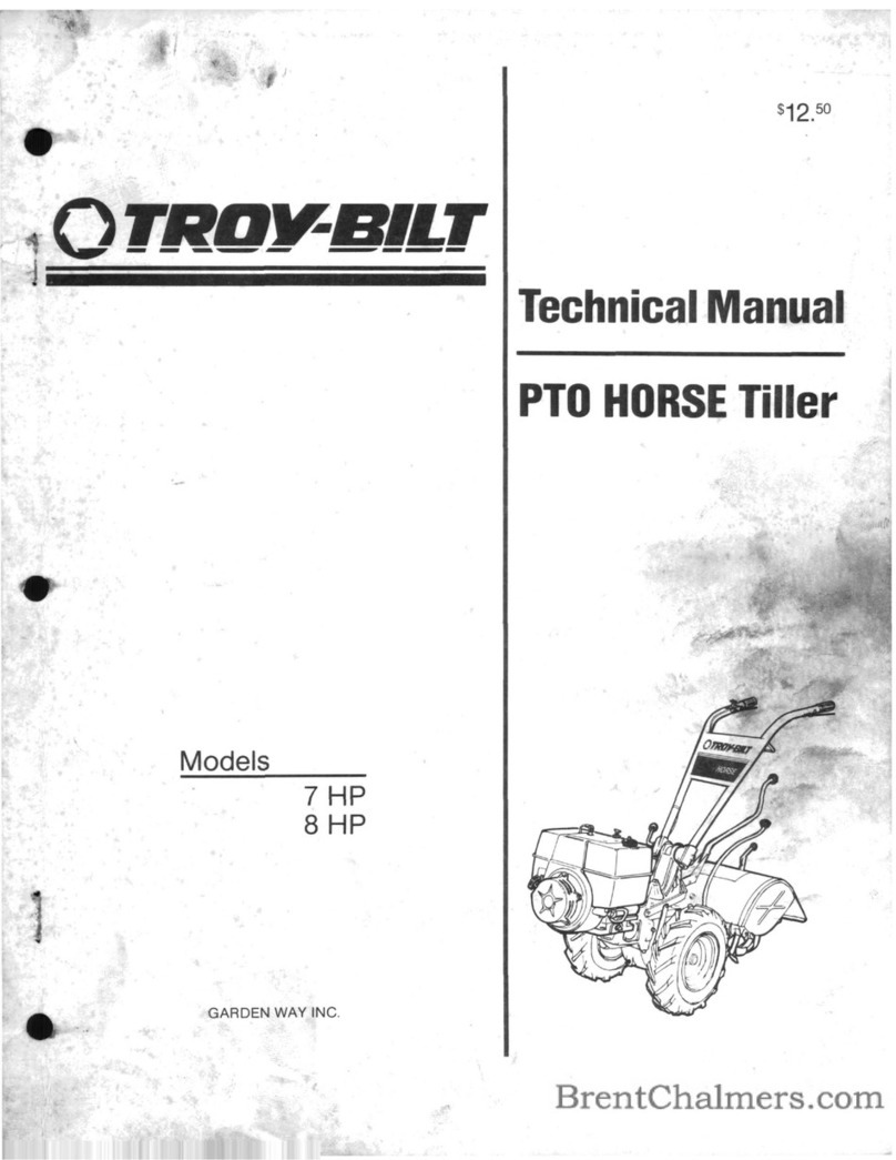
  9. Troy-Bilt 664D-Pony User manual

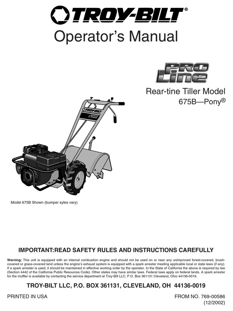
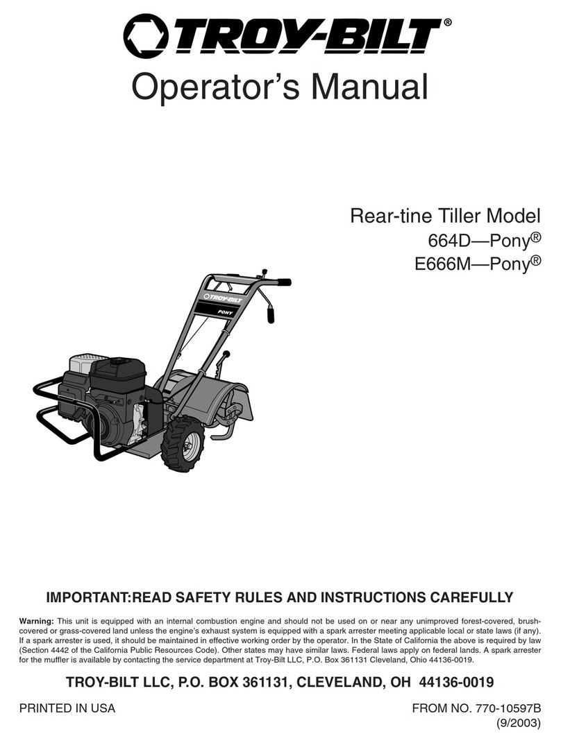
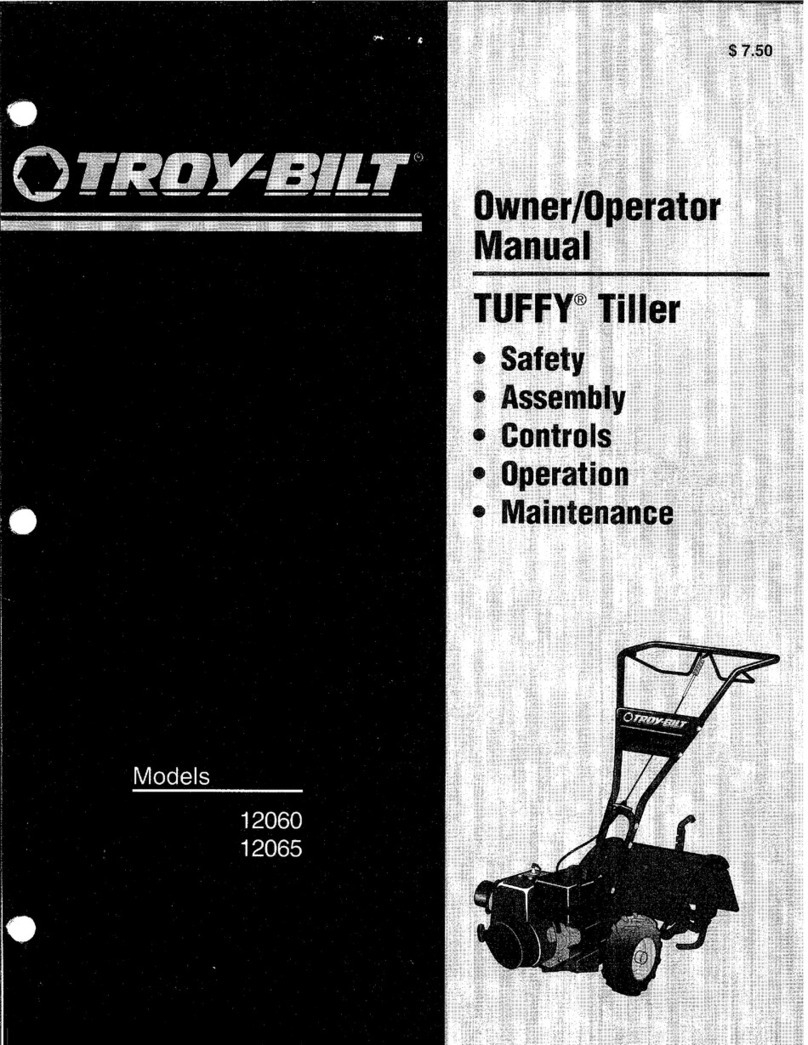
Troy-Bilt 664D-Pony User manual

Other manuals for 664D-Pony

2

This manual suits for next models

1

Other Troy-Bilt Tiller manuals

Troy-Bilt 675B Pony User manual

Troy-Bilt

Troy-Bilt 675B Pony User manual

Troy-Bilt 12087 Owner's manual

Troy-Bilt

Troy-Bilt 12087 Owner's manual

Troy-Bilt Super Bronco User manual

Troy-Bilt

Troy-Bilt Super Bronco User manual

Troy-Bilt PONY User manual

Troy-Bilt

Troy-Bilt PONY User manual

Troy-Bilt TB154 User manual

Troy-Bilt

Troy-Bilt TB154 User manual

Troy-Bilt 12097 Owner's manual

Troy-Bilt

Troy-Bilt 12097 Owner's manual

Troy-Bilt 769-00485A P/N 769-00485A User manual

Troy-Bilt

Troy-Bilt 769-00485A P/N 769-00485A User manual

Troy-Bilt 12097 User manual

Troy-Bilt

Troy-Bilt 12097 User manual

Troy-Bilt PONY User manual

Troy-Bilt

Troy-Bilt PONY User manual

Troy-Bilt Pony ES User manual

Troy-Bilt

Troy-Bilt Pony ES User manual

Troy-Bilt 12163 Instruction Manual

Troy-Bilt

Troy-Bilt 12163 Instruction Manual

Troy-Bilt 7HP Pony 12211 User manual

Troy-Bilt

Troy-Bilt 7HP Pony 12211 User manual

Troy-Bilt 12208 User manual

Troy-Bilt

Troy-Bilt 12208 User manual

Troy-Bilt 12210 Super Bronco User manual

Troy-Bilt

Troy-Bilt 12210 Super Bronco User manual

Troy-Bilt 664D-Pony User manual

Troy-Bilt

Troy-Bilt 664D-Pony User manual

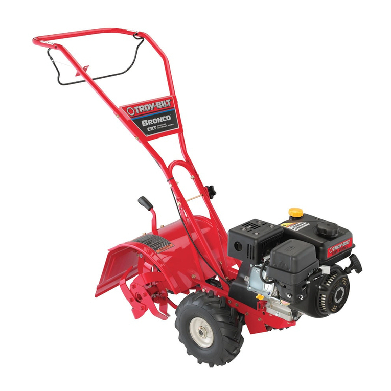
Troy-Bilt Bronco CRT User manual

Troy-Bilt

Troy-Bilt Bronco CRT User manual

Troy-Bilt Thoroughbred 654J User manual

Troy-Bilt

Troy-Bilt Thoroughbred 654J User manual

Troy-Bilt PONY 664D User manual

Troy-Bilt

Troy-Bilt PONY 664D User manual

Troy-Bilt Garden Way 12194 User manual

Troy-Bilt

Troy-Bilt Garden Way 12194 User manual

Troy-Bilt TB146EC User manual

Troy-Bilt

Troy-Bilt TB146EC User manual

Troy-Bilt TBGC User manual

Troy-Bilt

Troy-Bilt TBGC User manual

Troy-Bilt 634K--ProLine User manual

Troy-Bilt

Troy-Bilt 634K--ProLine User manual

Troy-Bilt 663B- -Pony User manual

Troy-Bilt

Troy-Bilt 663B- -Pony User manual

Troy-Bilt OEM-290-262 User manual

Troy-Bilt

Troy-Bilt OEM-290-262 User manual

Popular Tiller manuals by other brands

WIL-RICH 2500 Operator's manual

WIL-RICH

WIL-RICH 2500 Operator's manual

MTD 410R parts list

MTD

MTD 410R parts list

Viking HB 685 instruction manual

Viking

Viking HB 685 instruction manual

SMASH TLG415 instruction manual

SMASH

SMASH TLG415 instruction manual

FarmBoy FB-IC-209P user manual

FarmBoy

FarmBoy FB-IC-209P user manual

Craftsman 247.29931 Operator's manual

Craftsman

Craftsman 247.29931 Operator's manual

MTD FRT Series Operator's manual

MTD

MTD FRT Series Operator's manual

Craftsman 917.298353 owner's manual

Craftsman

Craftsman 917.298353 owner's manual

MTD OHV Series Original operating instructions

MTD

MTD OHV Series Original operating instructions

YAT YT5601-01 Assembly, Use, Maintenance Manual

YAT

YAT YT5601-01 Assembly, Use, Maintenance Manual

Craftsman 917.296010 owner's manual

Craftsman

Craftsman 917.296010 owner's manual

Scheppach MTP560 Translation from the original instruction manual

Scheppach

Scheppach MTP560 Translation from the original instruction manual

GARDEN WAY 12194 owner's manual

GARDEN WAY

GARDEN WAY 12194 owner's manual

Classen STAND-AER SA-25 Operator's manual and parts list

Classen

Classen STAND-AER SA-25 Operator's manual and parts list

Altrad ATIKA BH 1400 N Original instructions, safety instructions, spare parts

Altrad

Altrad ATIKA BH 1400 N Original instructions, safety instructions, spare parts

DR PILOT 2 Safety & Operating Instructions

DR

DR PILOT 2 Safety & Operating Instructions

AL-KO TL 1820 Instructions for use

AL-KO

AL-KO TL 1820 Instructions for use

breviglieri mekfarmer 120 Operating and maintenance

breviglieri

breviglieri mekfarmer 120 Operating and maintenance

manuals.online logo
manuals.online logoBrands
  • About & Mission
  • Contact us
  • Privacy Policy
  • Terms and Conditions

Copyright 2025 Manuals.Online. All Rights Reserved.

0TROY RILTr"
Operator's Manual
Rear-tine Tiller Model
664D--Pony
IMPORTANT:READ SAFETY RULES AND INSTRUCTIONS CAREFULLY
Warning: This unit is equipped with an internal combustion engine and should not be used on or near any unimproved forest-covered, brush-
covered or grass-covered land unless the engine's exhaust system is equipped with a spark arrester meeting applicable local or state laws (if any).
If a spark arrester is used, it should be maintained in effective working order by the operator. In the State of California the above is required by law
(Section 4442 of the California Public Resources Code). Other states may have similar laws. Federal laws apply on federal lands. A spark arrester
for the muffler is available by contacting the service department at Troy-Bilt LLC, P.O. Box 361131 Cleveland, Ohio 44136-0019.
TROY-BILT LLC, RO. BOX 361131, CLEVELAND, OH 44136-0019
PRINTED IN USA FROM NO. 770-10597
(12/2001 )
TABLE OF CONTENTS
Content Page
Calling Customer Support .................................................... 2
Safety ................................................................... 3
Assembly ................................................................. 6
Features and Controls ....................................................... 11
Operation ................................................................ 14
Maintenance .............................................................. 20
Tiller Attachments .......................................................... 28
Troubleshooting ........................................................... 29
Parts List ................................................................. 30
Warrany Information ........................................................ Back Cover
FINDING MODEL NUMBER
This Operator's Manual is an important part of your new Rear-tine Tiller. It will help you assemble, prepare and main-
tain the unit for best performance. Please read and understand what it says.
Before you start assembling your new equipment, please locate the model plate on the equipment and copy the infor-
mation from it in the space provided below. This information is very important if you need help from our Customer
Support Department or an authorized dealer.
You can locate the model number by looking at the rear surface of the tine shield. A sample model plate is
explained below. For future reference, please copy the model number and the serial number of the equipment
in the space below
O BILT" TROY-BILT LL(
P. O. BOX 361131
www.troybilt.com CLEVE_ND,OH_136
330-558-7220
•866-840-648_
Copy Model Number Here
Copy Serial Number Here
ENGINEINFORMATION
The engine manufacturer is responsible for all engine-related issues with regards to performance, power-rating, speci-
fications, warranty and service. Please refer to the engine manufacturer's Owner's/Operator's Manual packed sepa-
rately with your unit for more information.
CALLINGCUSTOMERSUPPORT
If you have difficulty assembling this product or have any questions regarding the controls, operation or maintenance
of this unit, please call the Customer Support Department.
Call 1- (330) 558-7220 or 1- (866) 840-6483 to reach a Customer Support representative. Please have
your unit's model number and serial number ready when you call. See previous section to locate this
information. You will be asked to enter the serial number in order to process your call.
Safety
This machine meets voluntary safety standard B71.8
- 1996, which is sponsored by the Outdoor Power
Equipment Institute, Inc., and is published by the
American National Standards Institute.
Safety AlertSymbol
This isa safety alert symbol. It is usedin this
manualand on the unitto alertyou to potential
hazards. When you seethis symbol, readand
obeythe messagethat follows it. Failureto
obeysafety messagescould result in personal
injury or property damage.
WARNING
The engine exhaust from this product contains
chemicalsknowntothe Stateof Californiato cause
cancer,birthdefectsorotherreproductiveharm.
TRAINING
1. Carefullyreadthis
Owner's Manual,the sepa-
rateEngineOwner's
Manual,and any other literature you may
receive.Bethoroughly familiar with the
controls and the proper useof thetiller
and its engine.Know how to stop the unit
and disengagethe controls quickly.
2. Neverallow children to operatethe
tiller. Neverallow adults to operatethe
tiller without proper instruction.
3. Keepthe areaof operationclearof all
persons,particularly children and pets.
4. Keepin mind that the operator or user
is responsiblefor accidents or hazards
occurring to other people,their property
and themselves.
PREPARATION
1. Thoroughly inspectthe areawherethe
tiller is to be usedand removeall foreign
objects.
2. Be sureall controls are releasedand
the WheelGearLeveris in ENGAGE
beforestarting the engine.
3. Do not operatethetiller without
wearing adequateouter garments. Avoid
loosegarments or jewelry that could get
caught in moving parts.
4. Donotoperatethetiller whenbarefoot
or wearingsandals,sneakers,or light
footwear.Wearprotectivefootwearthat will
improvefooting on slipperysurfaces.
5. Donottill nearundergroundelectric
cables,telephonelines,pipesor hoses.If in
doubt, contactyourtelephoneor utility
company.
6. Warning: Handlefuelw_thcare;it is
highlyflammableand itsvaporsare explo-
sive. Takethefollowing precautions:
a. Storefuel in containersspecifically
designedfor this purpose.
b. Thegas capshall neverbe removed
or fuel addedwhile the engine is
running. Allow the engineto cool
for severalminutes beforeadding
fuel.
c. Keepmatches,cigarettes,cigars,
pipes, open flames, and sparks
awayfrom the fuel tank and fuel
container.
d. Fillfuel tank outdoors with extreme
care. Neverfill fuel tank indoors.
Usea funnel or spout to prevent
spillage.
e. Replaceall fuel tank and container
caps securely.
f. If fuel is spilled, do notattempt to
start the engine, but movethe
machine awayfrom the area of
spillageand avoid creating any
source of ignition until fuel vapors
havedissipated.
7. Never makeadjustmentswhen engine
is running (unless recommendedby
manufacturer).
OPERATION
1. Do not put handsor feet near or under
rotating parts.
2. Exerciseextremecaution when on or
crossing graveldrives, walks, or roads.
Stayalert for hidden hazardsor traffic. Do
not carry passengers.
3. After striking a foreign object, stop the
engine(and removethe ignition key on
electricstart models), disconnect the
spark plug wire and prevent it from
touching the spark plug, carefully inspect
the tiller for anydamage,and repair the
damagebefore restarting and operating
the tiller.
4. Exercisecaution to avoid slipping or
falling.
5. If theunit shouldstartto vibrateabnor-
mally,stop theengine(andremovethe
ignition key onelectricstartmodels).Dis-
connectthespark plugwire andpreventit
from touching thespark plug,and check
immediatelyfor thecause.Vibration is
generallya warning of trouble.
6. Stopthe engine (and remove the igni-
tion keyon electric start models), discon-
nectthe spark plug wire and prevent it
from touching the spark plug whenever
you leavethe operating position, before
unclogging thetines, or when makingany
repairs, adjustments or inspections.
7.Takeallpossibleprecautionswhen
leavingthemachineunattended.Stopthe
engine.Removeignitionkeyonelectric
startmodels.Disconnectsparkplugwire
andmoveitawayfromthesparkplug.
MoveWheelGearLevertoENGAGE.
8. Beforecleaning, repairing, or inspect-
ing,stop the engine,remove the ignition
keyon electric start models,and make
certain all moving parts havestopped.
Disconnectthe spark plug wire and
prevent itfrom touching the spark plug to
preventaccidentalstarting. On electric
start models,always removethe cable
from the negativeside (-) ofthe battery.
9. Always keepthe tiller tine hood flap
down, unless using the hiller/furrower
attachment.
lB. Never usethe tiller unless proper
guards, plates,or othersafetyprotective
devicesare in place.
11. Do not run engine in an enclosed
area.Engineexhaustcontains carbon
monoxide gas,a deadlypoisonthat is
odorless,colorless, and tasteless.
12. Keepchildren and pets away.
13. Never operatethetiller under
enginepoweriftheWheel GearLever is
in DISENGAGE(FREEWHEEL).In this
position,thewheels will not holdthe
tiller backandthe revolvingtines could
propelthetiller rapidly, possibly
causinglossofcontrol.Always movethe
WheelGearLeverto ENGAGEbefore
startingthe engine or engagingthe
tines/wheelswith the ForwardClutch
Control or the ReverseClutchControl.
14. Beawarethatthe tiller may unex-
pectedlybounceupwardor jump
forwardif thetines shouldstrike
extremelyhardpackedsoil, frozen
ground,or buriedobstacleslike large
stones,roots,or stumps.If in doubt
aboutthe tilling conditions,alwaysuse
thefollowingoperatingprecautionsto
assistyou in maintainingcontrolofthe
tiller:
a. Walk behindand toone sideofthe
tiller, usingone handon thehan-
dlebars. Relaxyourarm, butusea
securehandgrip.
b. Useshallowerdepth regulatorset-
tings, workinggraduallydeeper
with eachpass.
c. Useslowerenginespeeds.
d. Clearthetilling area ofall large
stones,rootsandotherdebris.
e. Avoidusingdownwardpressure
on handlebars.If needbe, use
slightupwardpressuretokeepthe
tinesfrom diggingtoodeeply.
f. Beforecontactinghardpackedsoil
at the endofa row, reduceengine
speedand lift handlebarstoraise
tinesout ofthesoil.
g. In an emergency,stoptines and
wheelsbyreleasingwhichever
ClutchLeveris engaged.Do not
attemptto restrainthetiller.
15. Do not overloadthetiller's capacity
by attempting to till too deeplyat too fast
a rate.
16. Neveroperatethe tiller at high trans-
port speeds on hard or slippery surfaces.
Look behind and usecarewhen backing
up.
17. Do not operatethe tiller ona slope
that istoo steepfor safety.When on
slopes, slow down and makesureyou
havegood footing. Never permit the tiller
to freewheeldown slopes.
18. Neverallow bystanders nearthe unit.
19. Onlyuseattachments and acces-
sories that areapproved bythe tiller
manufacturer.
20. Usetiller attachments and acces-
sories when recommended.
21. Neveroperatethetiller without good
visibility or light.
22. Neveroperatethetiller ifyouaretired,
or underthe influenceof alcohol,drugsor
medication.
23. Operatorsshallnottamperwith the
engine-governorsettingson themachine;
thegovernorcontrolsthemaximumsafe
operatingspeedto protectthe engineand
all movingpartsfrom damagecausedby
overspeed.Authorizedserviceshallbe
soughtif a problemexists.
24. Donottouch enginepartswhich may
be hotfrom operation.Letpartscooldown
sufficiently.
25. Thebatteryon electricstartmodeltillers
containssulfuricacid.Avoidcontactw_h
skin,eyes,or clothing.Keepout ofthe
reachofchildren.
Antidote-External Contact:Flushimme-
diatelywith lots of water.
Antidote-Internal: Drinklargequantities
ofwateror milk.Followwith milkof
magnesia,beateneggs or vegetableoil.
Calla doctor immediately.
Antidote-EyeContact:Flushwith water
for 15 minutes.Getpromptmedical
attention.
26. Batteriesproduceexplosivegases.Keep
sparks,flame,andsmoking materialsaway.
Ventilatewhenchargingbatteriesor when
usingabatteryin an enclosedspace.
ALWAYSwearsafetygoggleswhen
working nearbatteries.
27. Pleaseremember:You canalwaysstop
thetinesand wheelsby releasingthe
ForwardClutchControlLeveror the
ReverseClutchControlknob(whichever
controlyou haveengaged),or by moving
the EngineThrottleControlLever(located
onengine)to STOPon recoilstartmodels
or byturningthe ignitionkeyto OFFon
electricstartmodels.
28. Toloador unloadthetiller, seethe
instructionsinSection4 ofthis Manual.
29. Useextremecautionwhen reversingor
pullingthemachinetowardsyou.
30. Starttheenginecarefullyaccordingto
instructionsandwith feetwellawayfrom
thetines.
31. Neverpick up or carrya machinewhile
the engineis running.
MAINTENANCEANDSTORAGE
1. Keepthe tiller, attachments and acces-
sories in safeworking condition.
2. Checkall nuts, bolts, and screws at
frequent intervalsfor proper tightness to
besure the equipment is in safeworking
condition.
3. Neverstorethetillerwith fuel in thefuel
tank insidea buildingwhereignition
sourcesarepresentsuchashotwaterand
spaceheaters,furnaces,clothesdryers,
stoves,electricmotors,etc. Allowengineto
coolbeforestoring in anyenclosure.
4. To reducethechancesofa fire
hazard,keeptheenginefreeofgrass,
leaves,or excessivegrease.
5. Storegasolinein a cool, well-venti-
latedarea,safelyaway from anyspark-
or flame-producing equipment.Store
gasoline in anapprovedcontainer,
safelyawayfrom the reachof children.
6. Referto the Maintenancesectionof
this Manualand in the separateEngine
Owner's Manualfor instructions if the
tiller isto be storedfor an extended
period.
7. Neverperform maintenancewhile
the engine is running or the spark plug
wire is connected,exceptwhenspecifi-
cally instructed to do so.
8. If thefuel tank hasto bedrained,do
this outdoors.
OperatingSymbols
Various symbols (shown here, with
worddescriptions)maybe usedon the
tillerandengine.
FAST SLOW STOP
6 8 I-'-I
CHOKE
STOP START ON
I÷1 R
REVERSE
CHOKE ROTATING
OFF TINES
<--o--->
LEVERDIRECTION
<--qBE
TILLERDIRECTION
z2.r
ENGAGED DISENGAGED
DECALS
Foryour safetyand the safety of others,
various safety messagedecalsare on your
unit (seeFigurebelow). Keepthe decals
cleanand legibleat all times. Contactyour
localservicedealer or the factory for
replacementsif any decalsare damagedor
missing.
Referto the Parts List pagesfor decal
locationsand part numbers.
TineWarning(onright
sideofhoodflap)
StartingStabilization(on
top ofengineor fuel tank)
Keyswitch Warning
(electricstart unit onl
WarningMessages
hgBelts
(ontopofbeltcover)
Figure1: LocationofSafetyand OperatingDecals
TO AVOID SERIOUS INJURY:
•READTHEOWNER'SMANUAL.
•KNOWLOCATIONSANDFUNCTIONSOFALLCONTROLS.
•KEEPALLSAFETYDEVICESANDSHIELDSIN PLACEANDWORKING.
•NEVERALLOWCHILDRENORUNINSTRUCTEDADULTSTOOPERATETILLER.
•SHUTOFFENGINEAND DISCONNECTSPARKPLUGWIRE BEFOREMANUALLYUNCLOG-
GINGTINESORMAKINGREPAIRS.
•KEEPBYSTANDERSAWAYFROMMACHINE.
•KEEPAWAYFROM ROTATINGPARTS.
•USEEXTREMECAUTIONWHEN REVERSINGORPULLINGTHEMACHINETOWARDSYOU.
Assembly
To prevent personal injury or property
damage,do not startthe engineuntil all
assembly steps are complete and you
havereadand understandthesafetyand
operatinginstructionsin this Manual.
INTRODUCTION
Carefullyfollow these assembly stepsto
correctly prepareyour tiller for use. It is
recommendedthat you read this Section
in its entirety before beginning assembly.
INSPECTUNIT
Inspectthe unit and carton for damage
immediately after delivery. Contactthe
carrier (trucking company) if you find or
suspect damage. Inform them of the
damageand request instructions for filing
a claim. To protectyour rights, put your
claim in writing and maila copy to the
carrier within 15 days after the unit has
been delivered.Contact usat the factory if
you needassistance in this matter.
UNPACKINGANDASSEMBLY
INSTRUCTIONS
STEP 1: UNPACKING INSTRUCTIONS
1. Removeanycardboard insertsand
packaging materialfrom the carton.
Removeany staplesfrom the bottom of
the carton and removethe carton.
2. Cutthe large,plastictie strap that
securesthetransmission tube to theship-
ping pallet. Leavethe handlebarson top
of the tiller to avoid damaginganycables.
3. A bag with loose hardwareis inside
the literature envelope. Checkthe con-
tents against thefollowing list and Figure
2-1. Contactyour local dealeror the
factory if any items are missing or
damaged.
NOTE: Forelectric start units, a second
hardware bag is located nearthe battery.
4. Thetiller is heavy. You should not
attempt to remove it from the shipping
platform until instructed to do so in these
"Assembly" steps.
HARDWAREBAGPARTSLIST
Fig.
Ref. Qty. Description
12 3/8-16 x 1"HexHd. Screw
2 1 KeyedWasher
31 WheelGearLeverKnob
41 Height Adjustment Flange
Screw (SeeFigure2-1A)
5 2 3/8" FlatWasher
6 2 #10 Lockwasher
72 3/8"-16 Nylock Lock Nut
8 2 #10-32 x 1/2" RoundHd.
Screw
92 #10-32 Nut
10 1 Cotter Pin (not used)
11 4 PlasticTie Strap (2 not used)
Tools/Materials Needed
for Assembly
(1) 3/8"open-end wrench*
(1) 7/16" open-endwrench* (electric
start unit only)
(2) 9/16" open-endwrench*
(1) 7/8" open-endwrench or 8" long
adjustablewrench
(1) Scissors (to trim plasticties)
(1) Ruler
(1) Small board (to tap plasticknob on
lever)
(1) Tire pressuregauge
(1) Cleanoilfunnel
(1) Clean,high-quality motor oil. Refer
to the separateEngineOwner's
Manualfor motor oil specifications
and quantity required.
*Adjustable wrenches may be used.
IMPORTANT:Motor oil must beadded to
the enginecrankcase beforethe engine is
started. Follow the instructions in this
"Assembly" Sectionand in the separate
EngineOwner's Manual.
NOTE:LEFTand RIGHTsides of thetiller
areas viewedfrom the operator's posi-
tion behindthe handlebars.
STEP 2: ATTACHHANDLEBARS
1. On electric start units, remove one
screw and Iockwasherfrom the curved
'T 600
7_ 8_'_ '_ _}9
11
B_
Figure2-1:Loosehardware(shownin
reducedsize).
Figure2.1A Hand/ebarheightadjustment
usestheflangeheadscrew,
Figure2-2: Onelectricstartunits,move
heightadjustmentbracketaside.
heightadjustment bracket (A, Figure2-2),
loosenthe second screw, and swing the
bracketto oneside.
2. Cut the large,plastic cableties that
securethe handlebarends to the handle-
bar mounting tabs on thetransmission
top cover.
3. Gently lift handlebar(do not over-
stretch attachedcable)and placehandle-
bar cross-brace (B, Figure2-3) in front of
curved height adjustment bracket (C).
Figure2-3: Forwardclutchcontrolcablenot
shownforclarity.
4. Withtheforwardclutchcable (N,
Figure2-4) on the insideofhandlebar,
position the handlebarendson the
outside of the two mounting tabs (M,
Figure2-3) on the transmission top
cover.
NOTE:Thecurved handlebarheight
adjustment bracketappearsasshown in
C,Figure2-3 for non-electric start units.
Forelectric start units, the bracket is loos-
enedand moved to one side.
5. Loosely attachthe handlebarsto the
mounting tabs with two 3/8-16 x 1"
screws (headsof screws go to insideof
tabs), 3/8" flat washersand 3/8"-16 lock
nuts (0, Figure2-4).
Figure24: Attachhandlebars.
6. On electricstart units, reattachthe
heightadjustment bracket (A,Figure2-2).
Tighten both screws securely. Makesure
the handlebarcross-brace (B, Figure2-3)
is under the bracket.
7. Move the handlebarsup or down to
align the threadedhole in the cross-brace
with one of thefour slots in the curved
heightadjustment bracket. Placethe
keyedwasher (E,Figure2-3) on the
flange head heightadjustment screw (F)
with the raisedkeys (edges)of the
washer facing down.
8. Threadthe heightadjustment screw
(F, Figure2-3) into the hole in the handle-
bar cross-brace, making surethat the
raisedkeyson thewasher fit into the slot
on the height adjustment bracket.
Tighten the heightadjustment screw
securely. Next, securelytighten the two
screwsand nuts in the ends ofthe han-
dlebar (M, Figure2-3).
9. To removethe tiller from its shipping
platform, first carefully unwrapthe wheel
gearcable (with attachedlever- see
Figure2-5) from around the chassis.
Movethe WheelGear Lever(G) to the
DISENGAGEposition--this allows the
wheels to rotatefreely. Usethe handle-
Figure25: CarefullyunwrapWheelGear
LeverandmovelevertoDISENGAGE.
barsto roll the tiller off the platform.
NOTE:TheWheelGearLeverwill be
installed later in this procedure.
IMPORTANT:Usethe DISENGAGEposi-
tion only when the engineis not running.
Beforestarting the engine,theWheel Gear
Levermust beplaced in the ENGAGE
position (seeSection 3 for details).
STEP3: ATTACHREVERSE
CLUTCH CONTROL CABLE
1. Carefullyunwrap the reverseclutch
control cable(H, Figure2-6) from its
shipping position and route it up along
the insideedge ofthe left side handlebar.
A knoband large hexnut (I) is installed
on the cable.
LeftSide ReverseClutch
Handlebar ControlKnob
Figure2-6:Attachreverseclutchcontrol
assemblytoslottedholeinhandlebarpanel
2. Insert the cableinto the slot in the
control paneland fit the threadedassem-
bly into the hole in theslot (seeFigure2-
6). Besurethat the flat side of the
threaded assemblyis aligned with the flat
side ofthe hole. Slide the hex nut (I) up
the cableand tighten it securely.
3. Testthe function of the reverseclutch
control cableby pulling the knob out and
releasingit. Theknob should returnto its
neutral position against the tapered
bushing. If it doesn't, contact your local
dealer or thefactory for technical
assistance.
STEP 4: ATTACH FORWARD
CLUTCH CONTROLCABLE
1. Removeanyfasteners (rubber bands,
tape, etc.)that may secure the Forward
Clutch Control levers (J, Figure2-7) to the
handlebar. I
Figure2-7: ForwardClutchControllevers
(J). Forwardclutchcontrollinkage(K).
2. Theforward clutch control cable(with
attachedspring) is hanging loosely near
the right-side wheel. Beingcareful not to
kink or stretch the cable, insert the z-con-
nector (L, Figure2-8 - end of the spring)
into the hole at the end of theforward
clutch control linkage(K, Figure2-7).
Figure2-8
3. Attach thecableadjuster (A, Figure
2-9) to the bracket onthe right-side han-
dlebar. Usetwo 1/2"wrenchesto loosen
thetwo jam nuts (B)just enoughto slide
the cableadjuster onto the bracket. Then
hand tighten the jam nuts.
Figure2-9
Incorrect cable adjustment could cause
the wheels and tines to rotate unexpect-
edly. Follow adjustment procedures
carefully. Failure to do so could result
in personalinjuryorpropertydamage.
4. Checkfor correct spring/cable tension
as instructed in Section5, Checkingand
Adjusting Forward ClutchBelt Tension.
5. Whentension is correct, tighten the
two jam nuts (B) securely.
STEP 5: CHECKTRANSMISSION
GEAROIL LEVEL
Thetransmission was filled with gearoil
at the factory. However,be sure to check
the oil levelat this time to make certain it
is correct.
IMPORTANT:Do not operatethe tiller if
the gear oil level is low. Doing so will
result in severedamageto thetransmis-
sion components.
1. With the tiller on levelground, pull the
Depth Regulator Lever(R, Figure2-13)
backand then slide it to thesecond notch
from thetop. NOTE:If the leverdoes not
move, lift the tine hood flap and look for a
plastictie securing the leverin place. Cut
and removethe tie.
2. Removethe oil levelcheck plug (M,
Figure2-10) on the left-side of the trans-
mission. (Dueto dried paint onthe plug
threads, it may require some force to
removethe plug thefirst time.) The gear
oil levelis correct if oil starts to flow out
of the hole asthe plug is removed. If so,
securelyreinstall the plug.
Figure2-10: Gear oil level checkplug,
3. If oil doesnot flow from the check
hole,add oil as follows:
NOTE:Donot useautomatic transmission
fluid or motor oil in thetransmission.
(a) Cleanareaaround the fill hole (N,
Figure2-11) and unscrewgear oil fill
plug.
Figure2-11: Addinggear oil,
(b) If adding only a few ounces of gear
oil, useAPI ratedGL-4 or GL-5 gear oil
havinga viscosity of SAE140, SAE85W-
140 or SAE80W-90. If refilling an empty
transmission, useonly GL-4 gear oil
havinga viscosity of SAE85W-140 or
SAE140.
(c) Usinga cleanfunnel, slowly add gear
oil until itflows from the gearoil level
checkhole (N, Figure2-11).
(d) Reinstalland tighten securelythe gear
oil fill plug (M, Figure2-10).
STEP 6: ADD MOTOR OIL TO ENGINE
Thetiller isshipped withoutoil in the
enginecrankcase.
IMPORTANT:Do not start the engine
without first adding motor oil. Severe
enginedamagewill result if the engineis
run without oil.
1. Referto the separateEngineOwner's
Manualfor motor oil specifications and
capacities.
2. With the unit on levelground, move
the Depth RegulatorLever(R, Figure2-
13) up or down until the engineis level.
3. Add motor oil as described in the
EngineOwner's Manual.
4. Move the Depth Regulator Leverall
theway down until the highest notch is
engaged. This placesthetines in the
"travel" position.
STEP 7: ATTACHWHEEL GEAR
LEVER
1. Insertthe WheelGearLever(P, Figure
2-12) up through the slot in the control
panelthat is labeled"WHEELGEAR."
2. Inserttwo #10-32 x 1/2" round head
screws down through the "+" marks on
the control paneldecaland securely
attachthe wheelgear mounting bracket
usingtwo #10 Iockwashersand #10-32
nuts.
Figure2-12: AttachWheel GearLever.
Figure2-13: Attachwheelgearcableand
reverseclutchcablewithcableties(S).
3. Use a small boardto tapthe Wheel
GearLeverknob securelyonto the lever.
4. Securethewheel gear cableand the
reverseclutch control cableto the left-
side handlebarwith two plastic ties (S,
Figure2-13) located abouttwo feet apart.
Snip off anyexcesstie length with
scissors.
STEP 8: CHECKAIR
PRESSURE IN TIRES
Usea tire pressuregauge to checkthe air
pressure in bothtires. Deflateor inflate
both tires equallyto 15-to-20 PSi
(pounds per squareinch). Be surethat
both tires are inflated equallyor the unit
will pull to one side.
STEP9: CHECKHARDWARE
FORTIGHTNESS
Inspectthehardwareonthe unitand
tightenanyloosescrews,boltsandnuts.
IMPORTANT:
•This completes assemblyfor recoil start
tillers. Readthe rest of this Manual,and
the separate EngineOwner's Manual,
beforeoperating thetiller.
• Electric start models--continue with the
Assembly Steps.
FeaturesandControls
Before operating your machine, care-
fully read and understand all safety,
controls and operating instructions in
this Manual, the separate Engine
Owner's Manual, and on the decals on
the machine.
Failure to follow these instructionscan
result inseriouspersonalinjury.
INTRODUCTION
This Sectiondescribesthe location and
function of the controls on your tiller.
Referto thefollowing section "Operation"
for detailedoperating instructions.
Practiceusing thesecontrols, with the
engine shut off, until you understandthe
operationof the controls and feelconfi-
dent with them.
IMPORTANT:Referto the separateengine
manufacturer's EngineOwner'sManual
for information aboutthe controls on the
engine.
WHEEL GEAR LEVER
This lever(A, Figure3-1) hastwo posi-
tions: ENGAGEand DISENGAGE.
Inthe ENGAGEposition, the wheelswill
startturning when either the Forward
ClutchControl or the ReverseClutch
Control is engaged(the tines will also
startturning when either clutch is
engaged).
Figure3-1: Controlslocatedon handlebar.
The DISENGAGEposition placesthe
wheels in thefreewheeling modeto allow
the unitto be movedwithout the engine
running. Usethe DISENGAGEposition
only whenthe engine is not running. See
"DANGER"statementthat follows.
To shift to ENGAGE,gently (do notforce)
move the leverforward while also rolling
the tiller afew inchesforward or back-
ward. Moving the tiller helpsto align the
shift mechanismwith the transmission
wheel drive gears.
To shift to DISENGAGE(freewheel),
move the leverrearward, without rolling
the tiller. Thewheelswill roll freely
when the lever is properly set in the
DISENGAGEposition.
FORWARD CLUTCH CONTROL
Thetwo interconnected levers (B, Figure
3-1) control the engagementof forward
drive to the wheelsand tines.
To Operatethe ForwardClutchControl:
1. Beforeengaging the Forward Clutch
Control, put the WheelGearLeverin the
ENGAGEposition (see"WARNING"
below).
2. Pull up and hold one or both of the
levers against the handlebargrips to
engagethewheels and tines.
3. ReleaseBOTHleversto disengage
(stop) the wheels andtines. All forward
motion will stop (the enginewill continue
to run).
Never place the Wheel Gear Lever in
DISENGAGE (Freewheel) when the
engine is running.
Having the Wheel Gear Lever in
DISENGAGE and then engaging the
tines/wheels with either the Forward
Clutch Control or the Reverse Clutch
Control could allow the tines to propel
the tiller rapidlyforwardor backward.
Failure to follow this instruction could
result in personal injury or property
damage.
Never engagethe wheels and tines with
the Forward Clutch Control or the
Reverse Clutch Control unless the
Wheel GearLeveris in ENGAGE.
Engagingthe ForwardClutch Controlor
the Reverse Clutch Control when the
wheels are not engagedcouldallow the
tines to rapidly propelthe tiller forward
or backward.
Failure to follow this warning could
result in personal injury or property
damage.
REVERSECLUTCHCONTROL
TheReverseClutch Control (C, Figure
3-1) controls the engagementof reverse
drive to thewheels and tines. The revers-
ingfeature isusedfor maneuveringthe
tiller only- neverengagethetines in
thegroundwhile goingin the reverse
direction.
,, Use extreme caution when reversing
or pulling the machine towards you.
Lookbehindto avoidobstacles.
,, Neverattempttotill in reverse.
Failure to follow this warning could
result in personal injury or property
damage.
ToOperatetheReverseClutchControl:
1. Putthe WheelGearLeverin the
ENGAGEposition (seethe "WARNING"
statementon previous page).
2. Stopall tiller motion by releasingthe
Forward ClutchControl levers.
3. Lift up the handlebarsuntil the tines
clearthe ground, look behindyou to avoid
anyobstacles,and then pull the Reverse
ClutchControl knob out. Thetines and
wheelswill rotate in a reversedirection.
4. Releasethe ReverseClutch Control
knob to disengage(stop) the wheels and
tines. All reversemotion will stop (the
enginewill continue to run).
,, Do not attempt to till too deeply too
quickly. Gradually work down to
deepertilling depths.
,, Placethe DepthRegulatorLever in the
"travel" position before starting the
engine. This position prevents the
tines from touching the ground until
youare readyto begintilling.
Failure to follow this warning could
result in personal injury or property
damage.
DEPTH REGULATOR
The Depth Regulatorlever (D, Figure3-2)
controls the tilling depth of thetines. Pull
the lever straight back and slide it up or
downto engagethe notched height set-
tings.
Figure3-2: DepthRegulatorLever.
The highest notch (leverall the way
down) raises thetines approximately
1-1/2 inches off the ground. This "travel"
position allows the tiller to be moved
without the tines digging into the ground.
Moving the lever up increasesthe tilling
depth. Thelowest notch allows a tilling
depthof approximately six to eight
inches,depending on soil conditions.
Forbestresults, alwaysbegintilling at
a veryshallowdepthsettingand gradu-
ally increasethetilling depth. Complete
details on using the Depth Regulatorare
found in the "Operation" Section of this
manual.
HANDLEBAR HEIGHT ADJUSTMENT
F
Figure3-3: Handlebarheightadjustment.
The handlebarheight is adjustableto four
different settings. Set the handlebar
heightto a comfortable setting, but keep
in mind that the handlebarswill be lower
when the tines are engagedin the soil.
To AdjusttheHandlebarHeight:
1. Stopthe engine,wait for all parts to
stop moving and then disconnect the
spark plug wire. Removethe ignition key
on electric start models.
2. Loosenthetwo screws atthe lower
ends ofthe handlebar.
3. Loosenthe heightadjustment screw
(E,Figure3-3) and pull the keyedwasher
(F)free of the slots in the curved height
adjustment bracket.
4. Move the handlebarsto the newslot
setting and insert the raisedkeyson the
keyedwasher into theslot. Tighten the
heightadjustment screw securely.
5. Retightenthe two screws at the ends
of the handlebar.
ENGINECONTROLS
Referto the engine manufacturer's Engine
Owner's Manual(included in the tiller lit-
erature package)to identify the controls
on your engine. Thefollowing two con-
trols are usedwhen stopping or starting
the engine.
IMPORTANT: Thecontrol for stopping
the recoil start engine is located on the
engine.
ENGINETHROTTLE CONTROLLEVER
TheEngineThrottleControlLever(located
on engine--seeFigure4-1) is usedto reg-
ulatethe engine speed. Onthe recoil start
modelonly, it isalso usedto stop the
engine (on the electric start model,the
electric start keyswitch is usedto stop the
engine). Thethrottle settings are shown
below.
IMPORTANT: See"Starting and Stopping
the Engine" in the "Operation" Sectionfor
detailedengine starting and stopping
instructions.
,_ FAST- Usefor most tilling and
cultivating projects.
•_b_ SLOW- Usewhen idling engine or
when slower tilling and cultivating
speedsare needed.
_STOP - Stops theengine (on
recoil start models only).