Truckweight SMART SCALE Installation instructions

SMART SCALE
INSTALLATION & OPERATING MANUAL
Handheld - In Cab Display ICD V_1.49
Display power cable connects to truck power 8-30 volt

2
Table of Contents
Page
1.0 Introduction. 3
2.0 Home Screen (Main Axle Screen). 4
3.0 MENU Screen. 5
4.0 Keypad Screen. 5
5.0 Truck Set-Up. 6
6.0 Sensor Screen. 8
7.0 Calibration Screen. 9
8.0 Zeroing. 10
9.0 Drop and Hook. 11
10.0 WIFI set up. 12
11.0 Steps to update firmware in Display. 14
12.0 Serial Data RS232 weight data to tracking devices. 15

3
1.0. Introduction:
The Display is designed for both In Cab mounting and Handheld operation is a touch screen
with RF range of about 1000 feet line of site.
Display works with weight sensors for all suspension types; air, spring, walking beam, Chalmers,
Tuff Track, etc…
Note, when first powering unit on, wait 30 seconds for sensors to synchronize, before pressing
any buttons.
The Display can be powered by Truck power and/or internal Lithium-Ion re-chargeable battery
(optional).
Battery life is 5 hours when fully charged continuous use. WIFI turned off. WIFI is only used if
the firmware is being upgraded, then turned off after upgrade is loaded.
The display can be set up for any truck and trailer configuration with a truck that can hook up to
three trailers connected to one truck. The system can drop and hook between an unlimited
number of trailers.
Top Line(s) are equipment ID. Each sensor will have a unique ID and will have the axle position,
Front Axle, Drive Axle, Trailer, for example. You can have a truck and four trailers connected to
a truck.
Hook, is used to drop and hook different trailers.
4
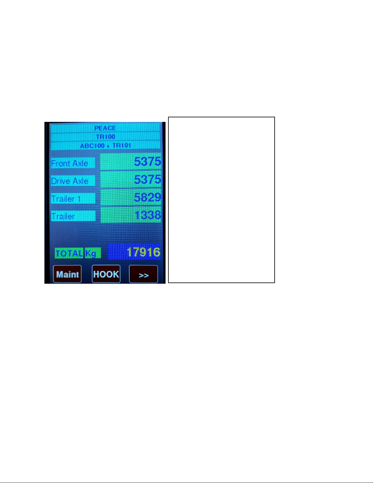
2.0 Home Screen - MAIN SCREEN AXLE WEIGHTS:
r
Once sensors are configured, press right arrows to display the pressure readings for each
sensor that appears on the Axle Screen (Home Screen). These reading will be recorded for
Empty Truck and Loaded Truck, after which, will entered into the Calibration screen for each
sensor.
First screen to show up after
Power up screen.
Showing axle weights and Total
Weight.
Maint Button (Maintenance)
Press to get Menu
Password: 11258
HOOK Button
Press to Hook or Drop equipment.
>> Button
Press to view pressures for
Calibration
5
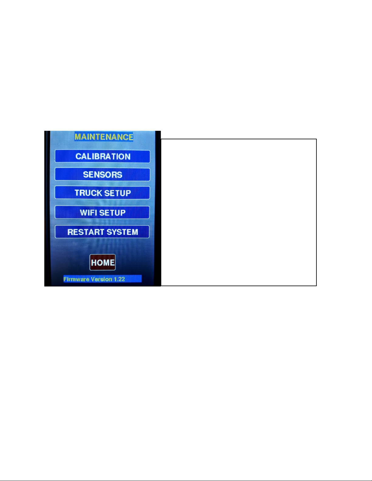
3.0 MENU. – Maintenance Screen:
4.0. Keypad:
MAINTENANCE MENU. Password: 11258
To get in this menu you need to first enter Password.
CALIBRATION permits user to calibrate each Sensor.
TRUCK SETUP must first be used to setup
Name of the Truck and other configurations.
WIFI setup is only used when firmware is
Required to be upgraded.
RESTART SYSTEM by touching or tapping
The unit will be rebooted immediately.
This needs to be done of sensors are changed

6
5.0. Truck Setup:
5.1 Truck Setup
KEYPAD
First screen is the numerical numbers.
To change it to Letters, press the A/1 button.
Press again for more letters.
Pressing the A/a button will shift the letters
To lower case.
Pressing the OK button will close this screen
With your text showing up in the other screen.
Or if it is a Password: 11258, will allow you to
enter MAINTENANCE mode.
The << button is not functional. Future use.
Truck setup (Configuration)
Selecting each item will show value just below
The list, use the Scroll on the right side to see
More items. Password: 11258
Truck Id is name of Truck this unit is installed on
Scale is either Imperial or Metric.
Min Lbs is the minimum increment it will show
In Main screen. Same with Min Kg (Metric).
Max Load is the limit but not used in this version.
Alert is either on or off, not used in this version.
To change any selection press the CHANGE
Button. And press the SAVE button to save it.
7
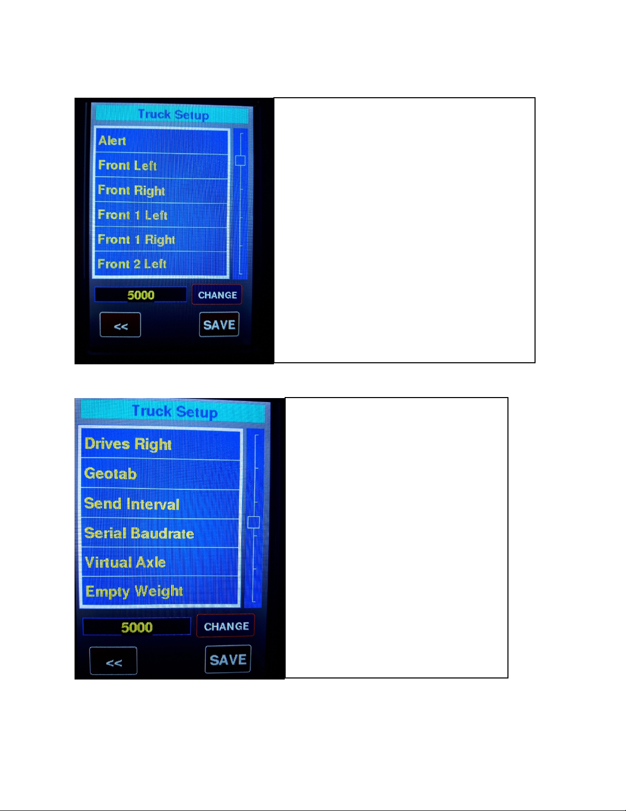
5.2 Truck Setup continued.
5.3 Truck Setup continued.
Truck setup (Continue)
Front Left or Right will show serial number
Of sensor attached to the Front Axle, Left or
Right is not important only the total of both.
The same for Front1, Front2, Drives.
These serial numbers are automatically picked
Up by the system but can be entered manually.
When powering up it may take up to 30 secondss
Or 1 minute for older sensors for all truck sensors
To be received. It is always better to enter them
Manually to prevent one sensor from being
Missed or was missing at power up.
Truck setup (Continue)
Geotab is a Communication to a host server,
But is not functional in this version.
Send Interval is also part of it and not functional.
Serial Baudrate is used by Geotab and Serial
Port and is not functional with this version.
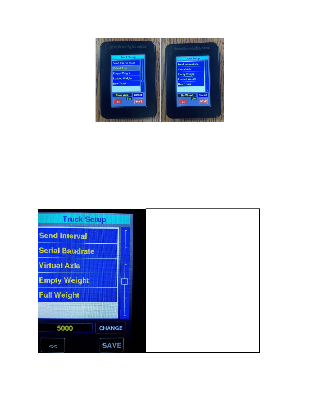
Virtual Axle is used when it is required for one
Of the Front Axle. Select this and press CHANGE
to choose which Axle you want this to be
active, select NO Virtual if you are not using it.
Empty Weight and Full Weight is used to make
The virtual axle proportional to Drive Axles.
8
5.4. Truck Setup Continued.
6.0 Sensor Screen Setup.
Truck setup (Continue)
Note, if your trailer is always the hooked
to the same truck, you can use the same
Equipment ID used for the truck is Truck
Set-up. If you use the same equipment
ID for the truck and trailer, the trailer will
appear on the axle screen without the
need to Hook.
9
Note, sensors usually come configured, whereby, Equipment ID, axle position (front axle,
Drives, Trailer, Lift, Jeep, Stinger, etc…), and sensor type (air, load cell, etc.. are pre-set before
shipping. Each sensor’s configuration can be changed, if required.
6.1 Sensors
6.2 Sensors continued.
7.0 Calibration: Password: 11258.
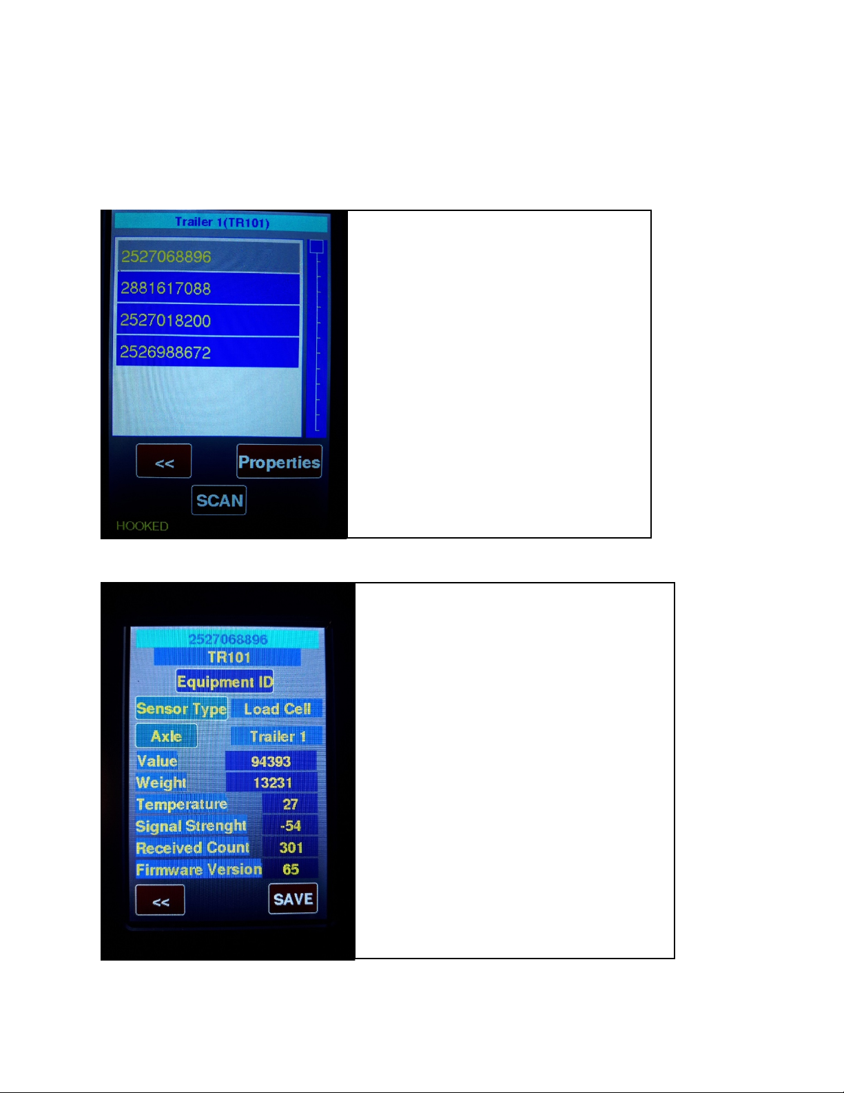
SENSOR list screen.
Select which sensor you wish to see or change
Properties of sensor, changing selection will
Show Equipment it belongs to and Axle.
Press Properties Button will go into next
Screen below.
SENSOR Properties screen.
Press Sensor Type button to change sensor type.
Press Axle to change axle and select from list.
Value shows last value received from sensor.
Weight shows last weight received.
Temperature show sensor internal temp in
Centigrade.
Signal Strength shows sensor range value.
Received Count shows the packets received.
Press Save to send changes to sensor.
10
7.1 First record the axle group weights from the inground scale and the Pressure Values by
pressing the >> arrow to display the pressures. Record them Empty and Loaded
7.2 Select a sensor.
7.2 Enter Calibration Values.
Calibration selection screen.
Pressing the Serial number selection will
Cause you to go into calibration of this
Sensor. Pressing the << button will return you
To Maintenance screen.
Press >> to
enter
Press << to
return

11
8.0 Zeroing:
8.1 Press >> from Home Screen to enter the zeroing screen. Zeroing is only used with to on
spring or walking beam spring suspensions. Zeroing does not have an effect on air sensors.
First line is the Serial # of the sensor.
2nd line is Equipment name this sensor belongs
To. 3rd line is Axle this sensor is on.
Live is the actual value or pressure from the Sensor.
Press EMPTY VALUE button to change. If the
Live value will show empty value id equipment
Is empty, and you can enter this value.
The Empty weight is the weight you want for
This value. Do the same for Full vehicle weight.
Pressing the SAVE button will send these values
To the sensor if OK you will see message at
Bottom of screen.
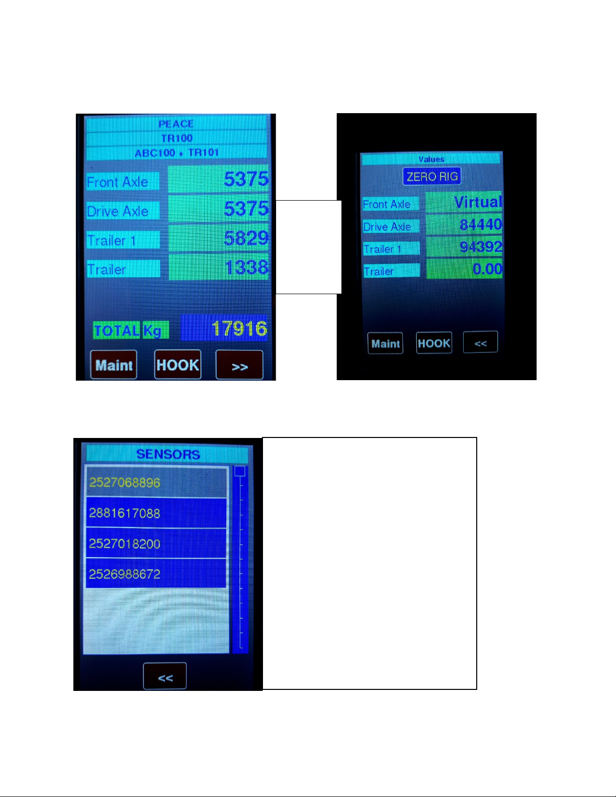
Values and Pressures Screen
ZERO RIG
Press to zero weights when
Equipment is empty.
Maint Button (Maintenance)
Press to get Menu
HOOK Button
Press to Hook or Drop equipment.
<< Button
Press to return to Axle Screen
12
8.2 Zeroing continued.
Press the left arrows to return to the Axle Screen (home screen).
9.0. Drop and Hook.
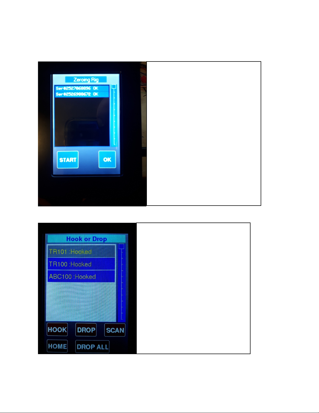
Make sure equipment is empty and
Equipment is stable.
Press START button to proceed.
OK Button will disappear and
Zeroing will commence.
All non AIR sensors will be zeroed.
Screen will show Serial numbers
zeroed. Note: you will get messages
if errors happen. If you try and zero
within 30 sec to 1 minute after
power up you may get errors due
to high traffic during Power up.
This screen will show which Equipment is
Hooked or not, Item in Grey is the selected
Item, you can drop this equipment by
Pressing DROP button, this will show up
The equipment Name only.
You can hook the selected item by first
Selecting by tapping the name in the list
Then press HOOK button.
If the equipment is not listed press the SCAN
Button, this will send a message to all sensors
To report within 10 seconds, sometimes if
13
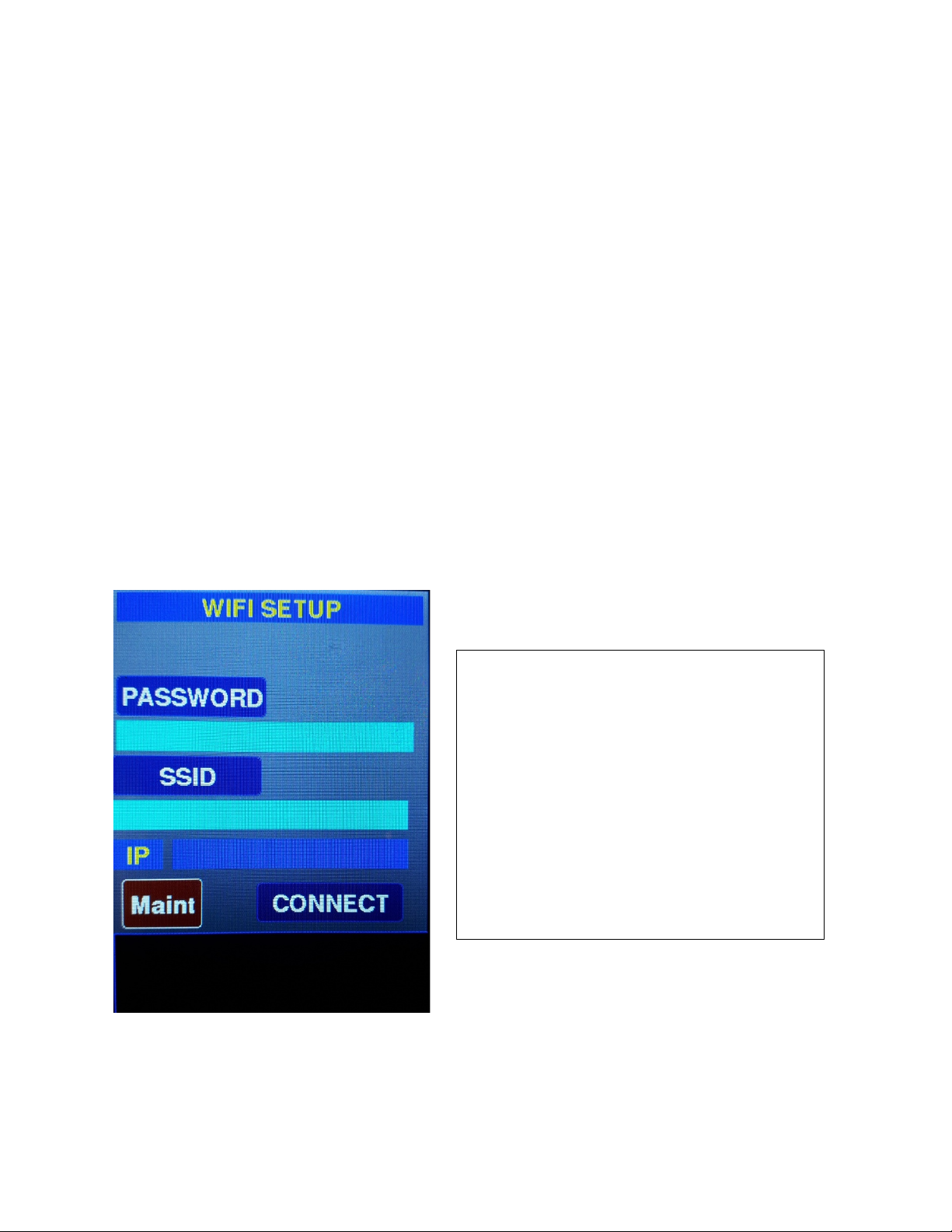
10.0. WIFI Set up:
This is used for downloading new firmware for this device. You must know the SSID of any nearby router and
Password. Enter these by Pressing PASSWORD and SSID
Buttons. Press Connect when done. These settings will be saved for future. Activations. The IP will show up in the
IP box or an error message if not. You May need to wait a few seconds before it
Shows up. Once you have the IP address you can use Any BROWSER on your computer or phone
Or tablet to download new firmware version Provided by TruckWeight Inc.
Shown below is the browser screen, Enter the IP obtained in the Address bar
(top line) in your browser and press ENTER
Or click.
Enter UserName -> tw
Enter Password-> 11258
And press login button.
Press Choose file and a list of your files will be
listed, you need to navigate to where your
File is located (.bin file) and select it. Then press
Update on your browser it will show progress
100% but that does not mean it is completed.
You now need to look at your Handheld screen at
the bottom you will see
Message saying Uploading. After less than a
minute your Handheld will restart with new
version.

14
E GAM A HADHELD
Things you need before programming:
1) Wi-Fi either from Phone(hotspot) or home Wi-Fi. Need to know your Wi-Fi ID and
Password, make sure it does not have any special symbols like @. If it has, we suggest
changing the ID and Password to a simple format.
Example: SSID – Truckweight Password – 12345678
2) Ask Truckweight to send the latest Program for Handheld to your email. (Example Version
1.43). After receiving the email save it to your device through which you are
programming.
Example: If I am using my iPhone. I got my latest version in my email.
a) Click on the file
b) On the top right, you will have send option with an up arrow, click on it. You
will get two options, Save to Account or Share File Via., Click on Share File
Via.
c) Now you will get different options to share, scroll to Save to Files and click
on It.
d) Choose just on My iPhone option and at the top right corner, you will have
the Save option and click on it.
If you are using Android or a computer, you will have a direct option to save in a known
location.
Program the Handheld:
1) Open Maintenance in the Handheld (password is 11258), go to Wi-Fi setup.
2) In Wi-Fi Setup click on SSID and enter your Wi-Fi name without any mistakes.
3) Next, click on the Password option and enter your Wi-Fi password and click Connect.
4) The HH will generate an IP address (Ex-192.168.188.1) at the bottom of the Handheld.
5) Open a web browser (Ex-Google Chrome or Safari). Type the IP address generated in HH
to the search / URL bar without www or .com and click enter/go.
6) This will open a Truckweight page, type ID – tw (lower case) and Password – 11258 and
click enter.
7) It will open a page to choose a file on the top left. Click choose file and choose the file you
saved in your device that came from our email and click on update. (Click Only once)
8) If you click update twice then the Handheld restarts and you need to start the process
again.
9) It will show the update percentage at the bottom (it goes to 100 immediately for
displaying but internally it takes 1-2 min. After few minutes the Handheld restarts itself
and will be programmed to the latest version.
10) If the Handheld was not programmed to the latest version, then you have to repeat from
step 1.

15
Connecting to tracking devices. Serial RS232 data format.
There are two settings, STANDARD and GEOTAB. Select STANDARD in Truck Setup
for all modems when Geotab is off. To Select GeoTab, only, in Truck Setup set to
ON. If it's OFF then it's in Standard output.
There are two ways to send serial data. Manually and Automatic. To manually
send data you must use the Print Button which will send
FLWC format to the Serial Port in either in Standard mode or GEOTAB. For
Automatic Select Interval time in seconds in Truck Setup.
You can also change Baud rate in the Truck Setup, default setting is 115200.
SDS is automatic data sent during a set time interval, and SDM is manually sent
data when print button is pressed.
FLWCV MAJOR.MINOR SDS/SDM*EQUIPMENT ID|VIRTUAL
SERIAL,AXLE,WEIGHT,1|SERIAL#,AXLE,PRESSURE,TEMPERATURE,WEIGHT,1|
repeat for all Serial # then last one will have tow bars ||followed by Total
Weight of all axles followed by CR LF.
Sample Data output
FLWCV 3.20
SDM*TRUCK02|999999,1,0,0,0,1|*PEACE|684759540,5,35.1,29.2,2003,1||2000
FLWCV 3.20
SDS*TRUCK02|999999,1,0,0,0,1|*PEACE|684759540,5,35.1,29.2,2003,1||2000
Axle Group and Temperature ID.

16
* "Front Axle",//1
* "Front Axle1",//2
* "Front Axle2",//3
* "Drive Axle",//4
* "Trailer",//5
* "Trailer 1",//6
* "Trailer 2",//7
* "Trailer 3",//8
* "Lift Axle",//9
* "Lift Axle 1",//10
* "Lift Axle 2",//11
* "Dolly",//12
* "Jeep",//13
* "Stinger",//14
* "Front Fork Arms",//15
* "Bucket Loader",//16
* "Fork Lift",//17
* “TEMP1”,//18
* “TEMP2”,//19
* “TEMP3”,//20
* “TEMP4”,//21
Up to 30 temperature sensors on any truck and or trailer. * “TEMP30”,//47
Table of contents
Popular Automobile Accessories manuals by other brands


etrailer
etrailer E-LEVEL product manual

Silvercrest
Silvercrest SCHW A1 Operation and safety notes

Shurco
Shurco truXedo Lo Profile owner's manual

Tripp Lite
Tripp Lite U280-CQ01 owner's manual

Silvercrest
Silvercrest SFA 40 A2 operating instructions

Horn Tools
Horn Tools HSW9900ISDMDY PA Mounting instructions