True blue power TB-14 Series Technical Document

Revision B •
A
pril 28, 2023
1 Manual Number 9019706 • Revision B, April 28, 2023
FOREWORD
This manual provides information intended for use by persons who, in accordance with current
regulatory requirements, are qualified to install this equipment. If further information is required,
please contact:
True Blue Power
c/o Mid-Continent Instrument Co., Inc.
Attn: Customer Service Dept.
9400 E. 34th St. N.
Wichita, KS 67226 USA
Phone 316-630-0101
Fax 316-630-0723
www.truebluepowerusa.com
www.mcico.com
We welcome your comments concerning this manual. Although every effort has been made to
keep it free of errors, some may occur. When reporting a specific problem, please describe it
briefly and include the manual part number, the paragraph/figure/table number and the page
number. Send your comments to:
True Blue Power
c/o Mid-Continent Instrument Co., Inc.
Attn: Technical Publications
9400 E. 34th St. N.
Wichita, KS 67226 USA
Phone 316-630-0101
Fax 316-630-0723
© Copyright 2023
Mid-Continent Instrument Co., Inc.
Download the current
version of this
installation manual
using your
smartphone or tablet.

2 Manual Number 9019706 • Revision B, April 28, 2023
TABLE OF CONTENTS
SECTION 1GENERAL DESCRIPTION 4
1.1INTRODUCTION 4
1.2PHYSICAL ATTRIBUTES 4
1.3UNIT ARCHITECTURE 4
1.4TECHNICAL SPECIFICATIONS 5
1.5IMPORTANT SAFETY INFORMATION 7
SECTION 2PRE-INSTALLATION CONSIDERATIONS 9
2.1COOLING 9
2.2EQUIPMENT LOCATION 9
2.3ROUTING OF CABLES 9
2.4LIMITATIONS 10
2.5MODIFICATION 10
SECTION 3INSTALLATION 11
3.1GENERAL 11
3.2PRE-INSTALLATION INSPECTION 11
3.3PARTS 11
3.4INSTALLATION 12
SECTION 4OPERATION 15
4.1DESCRIPTION 15
4.2CONSTRUCTION AND THEORY OF OPERATION 15
4.3OPERATIONAL MODES 16
4.4BATTERY COMMUNICATION 20
4.5PERFORMANCE 23
SECTION 5CONFORMANCE 24
5.1DISPATCH VERIFICATION AND IN-FLIGHT MONITORING 24
5.2INSTRUCTIONS FOR CONTINUED AIRWORTHINESS 24
5.3SOFTWARE UPDATE 25
5.4COMPONENT SERVICE 28
5.5STORAGE INFORMATION 28
5.6END OF LIFE 29
5.7DISPOSAL 29
5.8DO311-A COMPLIANCE QUALIFICATION FORM 30
5.9ENVIRONMENTAL QUALIFICATION STATEMENT 31

3 Manual Number 9019706 • Revision B, April 28, 2023
REVISION HISTORY
Rev Date Detail Approved
A
02/24/2023 Initial Release WVC
B 04/28/2023 Corrected Ipr (Table 1.4) and hold-down bar p/n (Sec
3.4.2). Provided additional details for Serial
Communications (Sec 4.4.3).Added exhaust gas
temperature (Sec 5.9).
WVC

4 Manual Number 9019706 • Revision B, April 28, 2023
SECTION 1 GENERAL DESCRIPTION
1.1 INTRODUCTION
The TB28-12V and TB14 series Advanced Lithium-ion Batteries, part number(s) 6430014-( ), are
designed to deliver high current capability to start piston and light turbine aircraft engines and
successively provide DC power capacity to the primary electrical bus in the event of generator
function loss. The TB28-12V/TB14 are sophisticated energy storage and power systems that utilize
state-of-the-art lithium-ion iron phosphate battery cell technology which provides improvement in
performance, safety, life and weight when compared to traditional or competing aircraft batteries.
The design of the battery includes detailed focus on key electrical, mechanical and software
elements that combine to provide exceptional performance and safety that meets and exceeds the
latest regulatory and industry standards. The TB28-12V/TB14 are complete battery solutions that
provide significant value and benefit to an aircraft designer, owner and operator.
Key features of the TB28-12V and TB14 batteries include real-time state of charge and state of
health resulting in maintenance-free operation with on-condition end of life. Multiple safety
protections and continuous data monitoring add value, reliability, and reduced cost of ownership
for the life of the product.
The TB28-12V and TB14 batteries require professional use and minimal service to deliver
maximum performance and value as designed. This manual contains information related to the
specifications, installation, operation, storage, scheduled service and other related topics
associated with the proper care and use of this product.
1.2 PHYSICAL ATTRIBUTES
The TB28-12V and TB14 batteries include a single, integrated assembly contained in a metal
enclosure with positive and negative power terminals and a 15-pin D-shell communication
connector. The top of the enclosure supports the use of a hold-down bar for typical aircraft
mounting. There is a 1-inch diameter vent port on top of the unit for an exhaust connection that
directs any released emissions appropriately.
1.3 UNIT ARCHITECTURE
The unit is comprised of two primary functional pieces:
Battery module
BMS (Battery Management System) board; a printed circuit board assembly that serves not
only to manage the battery system, but also controls charging and discharging.
Each battery consists of sixteen (16) cells. The 14 VDC battery (p/n 6430014-1, Model TB28-12V)
cells are arranged as four (4) groups of four (4) parallel cells, connected in series (4S4P); the 28
VDC battery (p/n 6430014-2, Model TB14) cells are arranged as eight (8) groups of two (2) parallel
cells connected in series (8S2P). Both -1 and -2 batteries include multiple temperature monitors to
assure safe operation. The cells are inter-connected with copper busbars and then tied directly to
the BMS board.
The BMS board is a microprocessor-based system that monitors the battery functions and protects

5 Manual Number 9019706 • Revision B, April 28, 2023
against such conditions as short circuit, over-temperature, over-discharge and others. The BMS
also controls enabling and disabling charge and discharge functions depending on the health of
the battery and generates battery status signals that are accessed through the 15-pin
communication connector for cockpit monitoring. An additional Resistance Temperature Detector
(RTD) is included and accessible through the 15-pin connector for external temperature
monitoring, independent from the BMS.
1.4 TECHNICAL SPECIFICATIONS
Electrical Attributes
Power Input:
-1
-2
14.4 VDC Nominal, 56 Amps Max
28.8 VDC Nominal, 28
A
mps Max
Power Output
-1
-2
13.2 VDC Nominal, Continuous Current 200 Amps
Power Peak Current (IPP) 810 Amps
Power Rated Current (IPR) 630 Amps
26.4 VDC Nominal, Continuous Current 100 Amps
Power Peak Current (IPP) 895 Amps
Power Rated Current (IPR) 380
A
mps
Battery Capacity
-1
-2
26 amp hours (Ah) @ 23°C
13 amp hours (Ah) @ 23°C
Table 1.1
Physical Attributes
Weight 10.0 pounds (4.6 kg)
Dimensions (see Figure 1.1)
(not including vent or
connectors)
6.3 x 5.6 x 4.9 inches
[160 x 142 x 124 mm]
Power Terminals M8 x 1.25 x 10mm deep thread, 13mm hex bolt
Communication Connecto
r
15-pin D-shell
Mounting Hold down bar (0.31 inch holes on 7.9 inch centers)
Table 1.2
Qualifications
Certification FA
A
/
TSO-C179b, Class
A
-4B
Performance Qualification RTCA/DO-311A (see section 5.8)
Minimum Operational Performance Standard for
Rechargeable Lithium Batteries and Battery Systems
Environmental Qualification RTCA DO-160G (see section 5.9)
Software Qualification RTCA/DO-178C, Design Assurance Level (DAL) A
Table 1.3

6 Manual Number 9019706 • Revision B, April 28, 2023
Figure 1.1
Unit Outline Drawing

7 Manual Number 9019706 • Revision B, April 28, 2023
1.5 IMPORTANT SAFETY INFORMATION
Read this safety information BEFORE maintaining or servicing the battery.
1.5.1 Symbol Definition
This section describes the precautions necessary for safe operations. The following safety
symbols have been placed throughout the guide.
Warnings identify conditions or practices that could result in personal injury.
Cautions identify conditions or practices that could result in damage to the equipment.
1.5.2 Handling Precautions
The battery’s energy is high enough to sustain an ARC flash. Always wear safety glasses,
fire retardant smocks, and use insulated tools when servicing the battery.
• Remove metal items such as rings, bracelets, and watches when working with battery
packs. A battery could produce a short circuit current high enough to weld jewelry to
metal and cause a severe burn.
• Always use appropriate Electrostatic Discharge (ESD) protection while working with the
battery pack.
• All connections for battery pack testing must include appropriate short-circuit protection.
• The battery pack service area shall be properly ventilated, and egress paths shall be
unobstructed.
• Specialized breathing filters are not required under normal use.
• Always use insulated tools.
• Never smoke or allow a spark or flame near the battery pack.
• Use caution to reduce the risk of dropping a metal tool on the battery. Dropping a tool
could spark or short circuit the battery pack.
• Turn all accessories off before removing the ground terminal.
• Use appropriate lifting devices or equipment for handling batteries; use battery handles
where provided.
CAUTION
W
ARNING
W
ARNING

8 Manual Number 9019706 • Revision B, April 28, 2023
1.5.3 Additional Precautions
The following design and operation factors are required for safe use.
• It is not acceptable to combine or use any battery cells or modules other than those
approved by True Blue Power within this battery pack.
There are no limitations in storing or using this battery in the vicinity of other battery
chemistries. This battery does not emit or absorb any gas during storage, transportation
or during normal operating conditions.
Batteries must not be installed with the output terminals reversed. A reversed battery
could be charged by other batteries in the circuit during discharge; or discharged by the
charging system during charge.
Battery terminals must be covered with non-conductive protective devices to avoid any
possibility of shorting during handling, shipping or storage.
1.5.4 Shipping
True Blue Power lithium-ion cells and batteries are designed to comply with all applicable
shipping regulations as prescribed by industry and regulatory standards. This includes
compliance with the UN recommendations on the Transport of Dangerous Goods, IATA
Dangerous Goods Regulations, and applicable U.S. DOT regulations for the safe transport
of lithium-ion batteries and the International Maritime Dangerous Goods Code. In
accordance with IATA and per UN 3480, PI 965, Section 1A and 1B, the TB14 series
Advanced Lithium-ion Battery will be shipped with a state of charge (SOC) not to exceed
30% of rated capacity. This battery is classified as a Class 9 Dangerous Good. If the
battery requires shipment, please contact the manufacturer for additional instructions on
proper procedures.
NOTE: The unit is shipped with approximately 30% state-of-charge (SOC). Upon receipt
the battery shall be fully charged using the procedures listed in this manual (prior to storage
and again prior to installation/use).
Upon receipt the battery shall be fully charged. Batteries that are stored shall be fully
recharged at a minimum every 6 months, following the procedure set forth in Section 5.2.2.
For more detailed storage instructions refer to Section 5.4.
CAUTION
CAUTION

9 Manual Number 9019706 • Revision B, April 28, 2023
SECTION 2 PRE-INSTALLATION CONSIDERATIONS
2.1 COOLING
No internal or external cooling of the unit is required. The unit is designed to operate over a wide
temperature range and includes internal thermal monitoring and protection circuits. See Section 4
for more details.
2.2 EQUIPMENT LOCATION
The TB28-12V and TB14 Advanced Lithium-ion Batteries are designed for mounting flexibility,
allowing for installation with no requirement for temperature or pressure control. Although not
required, optimum performance and life can be achieved by mounting the battery in a temperature
controlled section of the aircraft. In addition to altitude and temperature tolerance, the unit is
designed to withstand elevated levels of condensing humidity. However, installation locations
where the unit could be subject to standing or direct water exposure should be avoided. The unit
should be mounted in the upright position (vent on top).
Failure mode, effects, and criticality analysis of the TB28-12V and TB14 batteries have shown that
the potential for the release of toxic or flammable gases as a result of any potential condition is
extremely improbable. However, for additional risk mitigation, the unit is designed with a vent
which should be connected and diverted overboard in the event of such an occurrence. Details for
vent installation are provided in Section 3. The unit should not be installed in compartments where
lines, tanks or equipment containing fuel, oil or other flammable fluids are present. Installation near
potential sources of ignition should be avoided.
Consideration should be given to how the status and reporting functions of the battery will be
displayed within the aircraft. At a minimum, critical parameters determined at the time of
certification should be available to the pilot and/or crew. Additionally, existing aircraft systems
which are designed to work with traditional batteries may need alteration in order to accommodate
the slight change in voltage output of this lithium-ion battery and the communication capabilities
available.
2.3 ROUTING OF CABLES
The power terminal wires associated with the unit are heavy gauge wire and carry significant
power. Be aware of routing cables near other electronics or with other wire bundles that may be
susceptible to high energy flow.
Avoid sharp bends in both the power cables and the signal cabling and be cautious of routing near
aircraft control cables. Also avoid proximity and contact with aircraft structures, avionics
equipment, or other obstructions that could chafe wires during flight and cause undesirable effects.
Cables should not run adjacent to heaters, engine exhausts, or other heat sources. The signal
cable bundle wires are recommended to be no smaller than 24 gauge.

10 Manual Number 9019706 • Revision B, April 28, 2023
2.4 LIMITATIONS
The conditions and tests for TSO approval of this article are minimum performance standards.
Those installing this article, on or in a specific type or class of aircraft, must determine that the
aircraft installation conditions are within the TSO standards. TSO articles must receive additional
installation approval prior to being operated on each aircraft. The article may be installed only
according to 14 CFR Part 43 or the applicable airworthiness requirements.
The TB14 series operates at temperatures up to 70°C. If, however, internal cell temperatures
exceed 72°C, charging is disabled until cell temperatures fall below 62°C. Although the TB14
series operates at temperatures as low as -20°C, charging of the battery should not be performed
below -5°C. See Section 2.2 for limitations associated with equipment installation location.
2.5 MODIFICATION
This product has a nameplate that identifies the manufacturer, part number, description,
certification(s) and technical specifications of the unit. It also includes the “MOD” or modification
number representing notable changes in the hardware design of the unit.
Modification (MOD) 0 is the initial release of the product and is identified on the nameplate by the
lack of marking on the MOD numbers 1 through 9 (i.e. 1-9 are visible). All subsequent
modifications are identified on the nameplate by the marking/blacking out of that particular MOD
number (i.e. for MOD 1, the number 1 is not visible and 2-9 are visible - see Figure 2.1 for
examples). MODs do not have to be sequentially inclusive and may be applied independent of
each other.
For additional details regarding specific changes associated with each MOD status refer to the
product published Service Bulletins at www.truebluepowerusa.com.
Figure 2.1
Nameplate and MOD Status Example
MOD 0
MOD 1
MOD 1
& MOD 2

11 Manual Number 9019706 • Revision B, April 28, 2023
SECTION 3 INSTALLATION
3.1 GENERAL
This section contains mounting, electrical connections and other information required for
installation. These instructions represent a typical installation and are not specific to any aircraft.
3.2 PRE-INSTALLATION INSPECTION
Unpacking: Carefully remove the TB28-12V or TB14 battery from the shipping container. The
shipping container and packing are designed specifically for the transit of lithium batteries and
approved by international transportation agencies. These materials should be retained for use
should the unit require future shipment.
Inspect for Damage: Inspect the shipping container and unit for any signs of damage sustained in
transit. If necessary, return the unit to the factory using the original shipping container and packing
materials. File any claim for damages with the carrier.
Note: The unit is shipped at approximately 30% state of charge (SOC).
Upon receipt, the battery shall be fully charged using the procedures listed
in this manual (prior to storage and again prior to installation/use).
3.3 PARTS
3.3.1 Included Parts
A. TB28-12V / TB14 Advanced Lithium-ion Battery MCIA P/N 6430014-( )
B. Hold-down bar MCIA P/N 9018087
C. Installation and operation manual MCIA P/N 9019706
3.3.2 Available Parts
A. Connector Kit MCIA P/N 9019697-1
i. Power terminal lugs
ii. Communications connector kit
B. Vent Kit MCIA P/N 9019698-1
i. High temperature vent hose (48”)
ii. Vent clamps (x2)
3.3.3 Installer Supplied Parts
A. Wires
B. Appropriate hold-down hardware
CAUTION
12 Manual Number 9019706 • Revision B, April 28, 2023
3.4 INSTALLATION
The power terminals of the battery are always active and energized.
DO NOT SHORT TERMINALS AT ANY TIME!
Extreme care and caution should be applied when handling and connecting to the unit. Danger of
short circuit and subsequent arc flash, electrical burns or equipment damage can occur if not
handled properly.
Install the battery in the aircraft in accordance with the aircraft manufacturer’s instructions and the
following sections. If connecting batteries in parallel contact manufacturer for guidelines on parallel
operation.
3.4.1 Harness Preparation
Prepare aircraft wiring with mating connectors in accordance with the proper Wire Size and
Type (Table 3.1), Connector Locations (Figure 3.1) and Pin Identification Diagrams (Figure
3.2 and Table 3.2). Terminal bolts for negative and positive terminals torque should not
exceed 65 in-lbs. (7.3 Nm).
Use of PTFE, ETFE, TFE, Teflon or Tefzel insulated wire is recommended for aircraft use.
Recommended wire sizes and types are identified in Table 3.1 below. *Note: Wire gauge
size for power connections is dependent on the particular aircraft installation, taking into
consideration cable length, load profile, etc.
Table 3.1
Wire Size and Type
Wire Size and Type
Wire Gauge Wire Type Connecto
r
Pins
000 AWG * Stranded Coppe
r
Powe
r
+/-
18-24 AWG Stranded Coppe
r
Comm (7-pin)
A
-G
W
ARNING
13 Manual Number 9019706 • Revision B, April 28, 2023
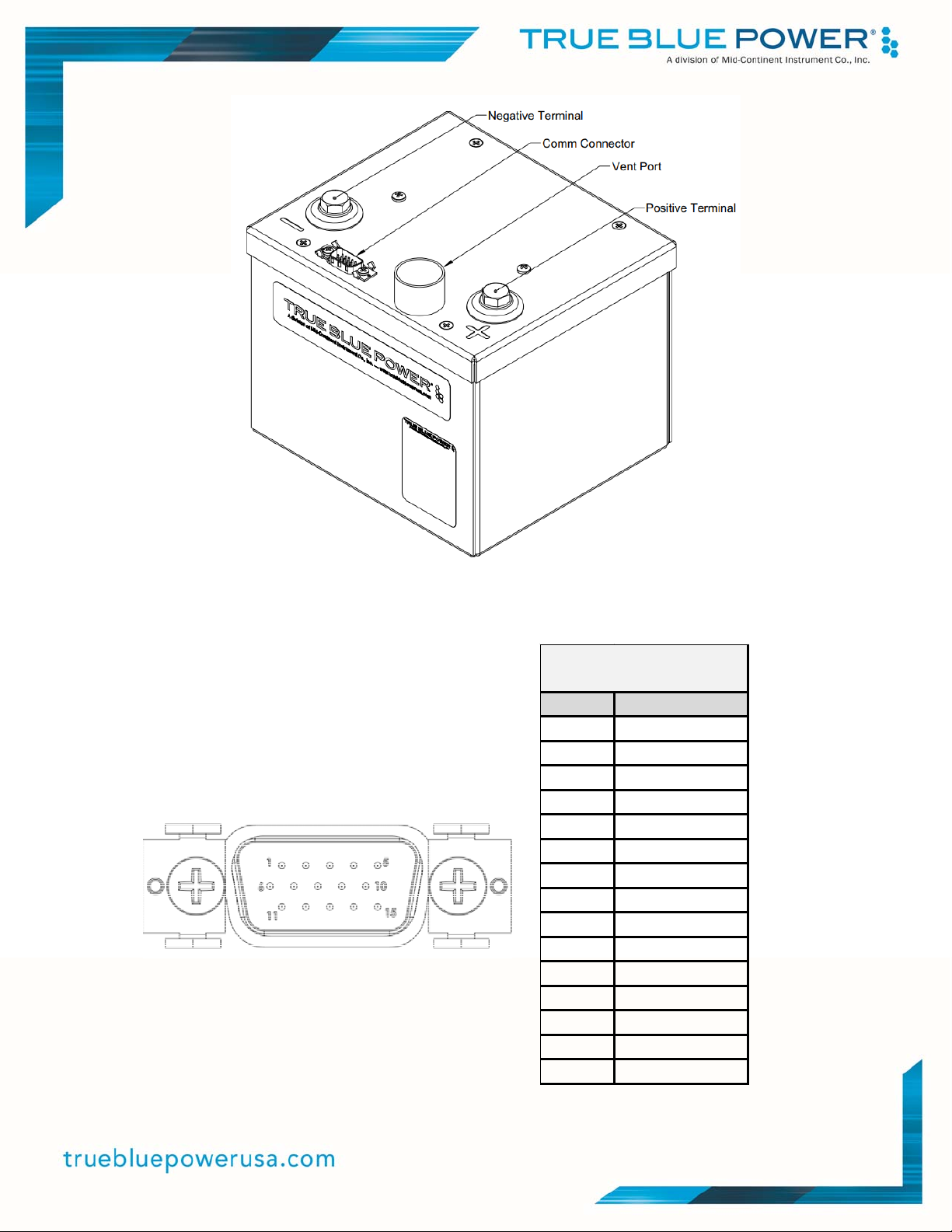
Figure 3.1
Connector Locations
Figure 3.2 Table 3.2
Communications Connector Communications Connector Pinout
Pin Function
1Fail/Fault+
2Fail/Fault‐
3 Reserved
4RTDHigh
5 Reserved
6 Dispatch‐
7 Reserved
8 Reserved
9 Reserved
10 RS232Out
11 Dispatch+
12 RTDLow
13 Battery‐
14 Reserved
15 RS232In
CommunicationConnector
(15‐pin)
14 Manual Number 9019706 • Revision B, April 28, 2023
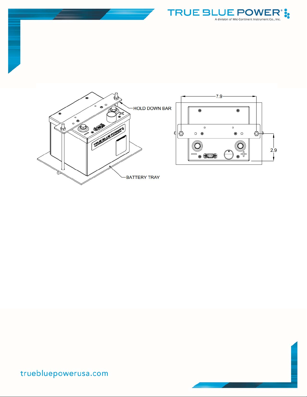
3.4.2 Securing the Unit
The TB28-12V and TB14 batteries are designed to be secured in the aircraft using hold-
down tie rods. The hold-down bar (P/N 9018087) can be attached to the battery using the
two existing screws included with the battery. The hold-down bar contains two holes, 0.310
inches (7.9 mm) in diameter, located 7.9 inches (200.7 mm) apart. Tie-down rods are
inserted through the holes and tightened to approximately 20 in-lbs (2.5 Nm).
Figure 3.3
Hold-Down Bar Attachment Method
3.4.3 Vent Installation
It is recommended that the battery be operated with the vent tube in place when installed in
the aircraft. The vent is located on the top of the unit, has a diameter of 1.0 inch (25.4 mm)
and is 0.7 inches (17.5 mm) tall. Use the vent tube and attachment hardware as supplied in
the Vent Kit, P/N 9019698-1. Contact True Blue Power for potential alternatives. The vent
tube should be properly and securely attached to an aircraft exit point which would allow
any gaseous emissions to be vented overboard. The TB28-12V and TB14 batteries
produce no emissions during normal operation. Emissions will only be present in the event
of a battery failure. Be sure to locate the vent where emitted gases would not be directed
toward any of the aircraft’s air intake ports.

15 Manual Number 9019706 • Revision B, April 28, 2023
SECTION 4 OPERATION
4.1 DESCRIPTION
The True Blue Power TB28-12V and TB14 Advanced Lithium-ion Batteries are designed to supply
power for starting an aircraft engine and providing emergency backup power to aircraft systems in
the event of primary power generation loss. It utilizes rechargeable Iron Phosphate lithium-ion cells
to deliver approximately 13.2 volts DC and 26 Ampere-hours (Ah) of capacity for a -1 unit and 26.4
volts DC and 13 Ampere-hours (Ah) of capacity for a -2 unit. It utilizes positive and negative power
terminals and supplies battery status and communication through a 15-pin D-shell connector.
4.2 CONSTRUCTION AND THEORY OF OPERATION
4.2.1 Battery Pack
The TB28-12V Advanced Lithium-ion Battery contains 16 individual prismatic lithium-ion
cells configured in a 4S4P (4 cells in series and 4 cells in parallel) configuration. Likewise,
the TB14 Advanced Lithium-ion Battery contains 16 individual prismatic lithium-ion cells
configured in an 8S2P (8 cells in series and 2 cells in parallel) configuration. Lithium-ion
battery cells have a very high energy density, producing more power than comparable
battery types in a significantly lighter package. The lithium iron phosphate chemistry
provides safety enhancements over alternative lithium technologies by producing a cell that
is more abuse tolerant to external conditions like over-charge or short circuit. It has a very
low self-discharge rate, high cycle life, and is more stable with significantly less-energetic
failure modes. These Lithium-ion cell advantages enhance typical lithium iron phosphate
chemistries by providing exceptional power and energy. The combination of these
characteristics makes it an excellent choice for use in aircraft applications where high power,
less weight, and enhanced safety are of utmost importance.
At a full, rested charge, each cell (and group of parallel cells) supplies approximately 3.3
VDC. When connected as described above, the -1 is rated to provide 26Ah of energy at
13.2VDC and the -2 is rated to provide 13Ah of energy at 26.4VDC. Monitoring wires are
used to report cell voltages to the BMS (Battery Management System) board for balancing,
protections, status and health. Additionally, each battery pack has multiple temperature
sensors with mechanical construction designed to secure the cells for an aircraft
environment.
4.2.2 Battery Management System (BMS)
The BMS board is independent of the cell pack and manages the power control and external
data interface of the battery. The BMS microcontroller and software provide controls that
manage charging and discharging of the battery. The BMS also will enable charge current
limiting if the charge current exceeds 56 Amps on the -1 (28 Amps on the -2) to protect
external circuitry/components (e.g. generator) from drawing too much current. This important
feature allows the battery to limit the amount of current it will accept from aircraft. Although
the very low internal impedance of lithium-ion cells can provide fast charging and high
power, it also can accept as much or more current than many aircraft power generation
systems can supply. The current limiting feature prevents the unit from utilizing the full
available power of the aircraft so that other key systems can remain active.

16 Manual Number 9019706 • Revision B, April 28, 2023
The software logic monitors the battery functions and provides protections for conditions
such as short circuit, over-temperature, over-discharge and others. The BMS generates
battery status; data that is provided to the aircraft through the 15-pin communication
connector for cockpit monitoring. Data is provided in serial (RS232), discrete and analog
formats.
The software is qualified to RTCA/DO-178C, Design Assurance Level A (DAL A). The
battery contains no airborne electronic hardware, known as AEH or complex hardware.
4.2.3 Resistance Temperature Detector
There is a single Resistance Temperature Detector (RTD) in the unit that supplies direct
analog resistance through two pins on the 15-pin connector and is characterized with a
resistive output (see Figure 3.2 and Table 3.2). See Section 4.4.1 for details correlating
resistance output with temperature.
4.2.4 Case and Hardware
Mechanical construction plays a key role in the design to specifically support optimal
functionality, mitigate and contain any potential failure, and withstand the expected aircraft
environment. Material selections, component design, assembly processes and test all
contribute to the performance and safety of the product.
Copper bus bars are used to connect the individual cells within the battery pack. The battery
pack is connected directly to the BMS board, which then provides connection to the positive
(+) and negative (-) terminals to deliver the battery power. Temperature and electrical
insulating materials are used to support the cells within the modules and isolate all internal
surfaces from the metal case. An internal aluminum heat sink connects to the battery lid for
thermal management, particularly during charge current limiting.
The case is constructed to address the unique needs of lithium technology. In particular, it is
designed to contain and direct emitted gases overboard, maintain safe external temperature
and pressure, constrain any debris or flame and ultimately prevent any effect on its
surroundings in the aircraft, even during a worst-case failure scenario.
4.3 OPERATIONAL MODES
The TB28-12V and TB14 batteries have two basic modes of operation: Sleep Mode and Active
Mode. These modes and associated functionality are explained below.
4.3.1 Sleep Mode
Sleep Mode is used to disable the power output of the battery and reduce internal energy
consumption to preserve resting state of charge. When the battery is in Sleep Mode, the
battery is not charging or discharging, all active communications are disabled, and internal
energy consumption is reduced by 90% with respect to Active Mode.

17 Manual Number 9019706 • Revision B, April 28, 2023
In Sleep Mode, a current of 3mA or more will transition the battery to Active Mode. The
battery is capable of monitoring the terminals for an external load or charge while in Sleep
Mode.
The battery will enter Sleep Mode when the battery is inactive:
The internal battery voltage is less than 13.75VDC (-1) or 27.5VDC (-2) and five
minutes after:
o No charge or discharge (<3mA)
o No protections actively being applied
4.3.2 Active Mode
In Active Mode, the battery is fully functional and available to provide power barring no
protections are being enforced and the battery is operating properly. In Active Mode, the
battery continuously monitors all cells and battery conditions to manage operation and
mitigate exceedances as needed through its various protection methods. Data and status
are available through the communication connector while in Active Mode. Each major
function available during Active Mode is described in further detail below in Figure 4.1.
The following figure summarizes the transition conditions between Sleep Mode and Active
Mode.
Figure 4.1
Operational Modes State Diagram
4.3.2.1 Engine Start
The TB28-12V and TB14 batteries can provide a peak current of 850A for the purpose of
aircraft engine starting. They will provide a maximum of 380A for up to 16 seconds and
200A (for a -1 unit) or 100A (for a -2 unit) continuously. Peak start currents of 360A (-1) or
180A (-2) can be produced with temperatures as low as -18°C (0°F). The low internal
impedance of the lithium-ion chemistry allows extremely high current delivery while
maintaining higher voltage than traditional battery types. This equates to a higher total
power delivery, producing quicker, stronger starts, lower engine temperatures, more start
attempts when needed, and a higher remaining battery capacity following engine start. The
higher voltage also means better power to supporting systems during an engine start.

18 Manual Number 9019706 • Revision B, April 28, 2023
4.3.2.2 Providing Aircraft Power
When the aircraft’s power generation systems are offline or fail, the unit will provide
immediate power to the equipment/loads on the associated power bus. As the unit’s
capacity is used, the voltage will begin to drop until the unit is fully depleted. A fully charged
unit will initially provide approximately 14 volts (-1) or 28 volts (-2). Depending on the load,
the battery will provide an average of approximately 12.7 volts (-1) or 25.5 volts (-2) for the
duration of discharge.
In order to avoid depleting the unit’s power and ensure availability for the next flight, be
sure to turn off all aircraft systems, lights and accessories after a flight. If the unit is
depleted, see Section 5.2 Maintenance for charging instructions.
4.3.2.3 Maintaining Charge
After an engine start, the unit recharges and maintains charge by accepting power from the
aircraft power generation system. During charging, the battery can draw up to 56A (-1) or
28A (-2) before the charge limiting activates. A fully depleted unit will completely recharge
in approximately 50 minutes (-1) or 35 minutes (-2). In typical applications, the unit is likely
to be fully re-charged from the aircraft power generation system within several minutes
following an engine start.

19 Manual Number 9019706 • Revision B, April 28, 2023
4.3.2.4 Battery Protections
The TB28-12V and TB14 Advanced Lithium-ion Batteries have built-in protections for
conditions that may exceed specified operating limits:
Protection Parameter(s) Action Recovery
Under Voltage
(low current)
for -1 units
If discharge current < 112A
and battery voltage < 8VDC
or
cell voltage < 1.8VDC
Discharging
disabled Battery Voltage > 10VDC and
cell voltage > 2.5VDC
Under Voltage
(high current)
for -1 units
If discharge current > 112A
and battery voltage < 7VDC
or
cell string voltage < 1.0VDC
Discharging
disabled Battery Voltage > 10VDC and
Cell string voltage > 2.5VDC
Under Voltage
(low current)
for -2 units
If discharge current < 56A
And battery voltage < 16VDC
or
cell voltage < 1.8VDC
Discharging
disabled Battery Voltage > 20VDC and
cell voltage > 2.5VDC
Under Voltage
(high current)
for -2 units
If discharge current > 56A
and battery voltage < 12VDC
or
cell string voltage < 1.0VDC
Discharging
disabled Battery Voltage > 20VDC and
Cell string voltage > 2.5VDC
Over Voltage Battery voltage > 15.2VDC (-1);
Battery voltage > 30.4VDC (-2)
or
Any cell voltage > 3.8 VDC
Charging
disabled
Battery voltage < 14.4VDC (-1) /
28.8VDC (-2)
and
All cell voltages < 3.6 VDC
Over Current Battery discharges > 380A for
more than 16 seconds
Discharging
Disabled
External Load removed or
charging current detected
Short Circuit Battery detects current > 900A
for > 100ms
Discharging
Disabled
External Load removed or
charging current detected
Over
Temperature
(Discharging)
Any cell temperature > 95°C
or
Discharge circuitry > 130°C
Discharging
Disabled
All cell temperatures < 80°C
and
Discharge circuitry < 90°C
Over
Temperature
(Charging)
Any cell temperature > 72°C
or
Charge control circuitry > 130°C
Charging
disabled
All cell temperatures < 62°C
and
Charge control circuitry < 90°C
Over Discharge Any cell string voltage
< 1.2VDC and current
< 100mA both for 10 seconds
Battery is
disabled
Factory Service
Cell Over
Temperature Fail
Any cell temperature > 110°C Battery is
disabled
Factory Service
Table 4.1
Battery Protections
This manual suits for next models
1
Table of contents
Other True blue power Batteries Pack manuals

Popular Batteries Pack manuals by other brands


Mophie
Mophie powerstation go rugged with air compressor operating instructions

SolaX Power
SolaX Power SOLAX BOX Quick installation guide

Aegis
Aegis ALF-036050A user manual

Mizco International
Mizco International ToughTested SOLAR 16 user manual

Belkin
Belkin TUNEPOWER F8E490EA Guía De Instalación Rápida

Solax
Solax Pocket WiFi V3.0 installation manual


