True blue power TC2000 Series Technical Document
Installation Manual and Operating Instructions
Model TC2000 Series
Static Electrical Power Converter
True Blue Power®is a division of Mid-Continent Instrument Co., Inc.
Mid-Continent Instrument Co., Inc.
dba Mid-Continent Instruments and Avionics
9400 E. 34th Street N.
Wichita, KS 67226 Manual Number 9019049
PH (800) 821-1212 FX (316) 630-0723 Rev C March 8, 2018

Rev C, March 8, 2018 2 Manual Number 9019049
FOREWORD
This manual provides information intended for use by persons who, in accordance with current
regulatory requirements, are qualified to install this equipment. If further information is required,
please contact:
True Blue Power
c/o Mid-Continent Instrument Co., Inc.
Attn: Customer Service Dept.
9400 E. 34th Street N.
Wichita, KS 67226 USA
PH (316) 630-0101
FX (316) 630-0723
www.truebluepowerusa.com
www.mcico.com
We welcome your comments concerning this manual. Although every effort has been made to
keep it free of errors, some may occur. When reporting a specific problem, please describe it
briefly and include the manual part number, the paragraph/figure/table reference and the page
number. Send your comments to:
True Blue Power
c/o Mid-Continent Instrument Co., Inc.
Attn: Technical Publications
9400 E. 34th Street N.
Wichita, KS 67226 USA
PH (316) 630-0101
FX (316) 630-0723
All products produced by Mid-Continent Instrument, Co., Inc., including those identified as Mid-
Continent Instruments and Avionics or True Blue Power, are designed and manufactured in
Wichita, KS, USA.
Copyright 2017
Mid-Continent Instrument Co., Inc.

Rev C, March 8, 2018 3 Manual Number 9019049
REVISION DETAIL
Revision Date Approved Detail
A 12/28/2017 BAW Initial release
B 01/26/2018 BAW
Corrected formatting issues. Incorporated FAA
comments.
C 03/08/2018 JRC
Changed paragraph 3.3.2.3 pin ‘E’ to pin ‘A’. Added
note page 5 on ground regulatory requirements.

Rev C, March 8, 2018 4 Manual Number 9019049
TABLE OF CONTENTS
SECTION 1GENERAL DESCRIPTION..................................................................................5
1.1INTRODUCTION ............................................................................................................5
1.2TECHNICAL SPECIFICATIONS ....................................................................................5
SECTION 2PRE-INSTALLATION CONSIDERATIONS ........................................................6
2.1COOLING .......................................................................................................................6
2.2EQUIPMENT LOCATION...............................................................................................6
2.3ROUTING OF CABLES..................................................................................................6
2.4LIMITATIONS .................................................................................................................6
SECTION 3INSTALLATION PROCEDURES ........................................................................8
3.1GENERAL INFORMATION ............................................................................................8
3.2UNPACKING AND INSPECTING EQUIPMENT ............................................................8
3.3CABLE HARNESS .........................................................................................................8
3.3.1Wire Gauge Selection .............................................................................................8
3.3.2Pin Assignment Information ....................................................................................9
3.3.3Example Wiring Diagrams.....................................................................................10
3.3.4Harness Verification ..............................................................................................10
3.4MOUNTING ..................................................................................................................12
3.5INSTALLATION COMPLETION ...................................................................................13
3.6INSTALLATION CAUTION...........................................................................................13
SECTION 4OPERATION .....................................................................................................14
4.1ELECTRICAL PERFORMANCE ..................................................................................14
4.2PROTECTIVE FEATURES ..........................................................................................14
4.2.1Remote On/Off ......................................................................................................14
4.2.2Over-Temperature.................................................................................................14
4.2.3Short Circuit And Over-Current .............................................................................14
SECTION 5CONFORMANCE ..............................................................................................15
5.1INSTRUCTIONS FOR CONTINUED AIRWORTHINESS ............................................15
5.2ENVIRONMENTAL QUALIFICATION STATEMENT ...................................................15

Rev C, March 8, 2018 5 Manual Number 9019049
1.1 INTRODUCTION
The model TC2000 Series Static Electrical Power Converter is a lightweight power converter that
translates an aircraft alternating current (AC) input of 115 volts at 360-800 Hertz to a 28 volt
direct current (DC) output. Additionally the TC2000 can be bench operated on AC Mains with
115 or 230 volts at 47-65 Hz input and provide a 28 volt direct current (DC) output (see Note 1
below).
The wide input operating voltage and frequency make the TC2000 suitable for nearly any
common business or commercial aircraft which provides 100-125 VAC between 360-800 Hertz.
The output of 71 amps @ 28 VDC produces 2000 watts of power to supply avionics,
instrumentation, seating, personal charging, lighting, and many other applications. The TC2000
Series Static Converter is FAA certified to TSO-C71 and tested to rigorous environmental
standards and levels of RTCA DO-160G. The small size and light weight in conjunction with its
installation flexibility (inside or outside the pressure vessel) make it an ideal choice for aircraft
power needs while reducing the challenges associated with other similar products.
Highlighted features include short circuit protection, overload capability, low voltage shut-down,
temperature monitoring, a self-resettable over-temperature disable and a remote on/off function.
The TC2000 Series has a robust Military-rated circular connector, and the rugged extrusion that
houses the unit is designed to help dissipate heat and provide mechanical strength against
vibration or other possibilities of damage. Two independent fans allow for a smaller unit and
quiet operation, and keep the internal components cool extending the life of the unit.
1.2 TECHNICAL SPECIFICATIONS
Electrical Attributes: Model TC2000
Input Voltage Aircraft: 115VAC nominal, 360-800 Hz.
AC Mains: 115VAC or 230VAC, 47 to 65 Hz. (Note 1)
Input Current (full load) 22 Amps nominal; 28 Amps max
Input Current (unit off) 2 Amps
Recommended Input Circuit Breaker 30 Amps (for 115VAC aircraft use)
Output Voltage 28VDC ± 0.5 VDC
Output Power 2000 watts (28VDC @ 71 Amps rated)
Efficiency 88% nominal
Table 1.1
Physical Attributes: Model TC2000
Weight: 9.9 lbs [4,49 kg]
Dimensions:
(not including connector mate)
14.00 inches x 6.32 inches x 3.46 inches (LxWxH)
[35,5 x 16,1 x 8,8 cm]
Mating Connector (and cable clamp): MCI P/N 9018993-1 and 9018550-2
Mounting: Base mount – orientation not critical
Table 1.2
Note 1: The TC2000 has not been tested to UL, CE, or other ground regulatory requirements. Powering from AC mains
is intended for testing or temporary use only.

Rev C, March 8, 2018 6 Manual Number 9019049
Qualifications: Model TC2000
Certification: FAA TSO-C71
Environmental Qualification: RTCA DO-160G Environmental Category; See
Section 5.2
Altitude: 35,000 feet
Temperature: -55°C to +70°C (-67°F to + 158°F)
Table 1.3
2.1 COOLING
No external cooling is required. The unit is equipped with two internal DC fans that are
thermostatically controlled. The fans normally run at a slow speed, but depending upon load and
ambient temperature one or both fans may operate at a higher speed.
Restriction to airflow can cause overheating of the unit and limit performance or reduce the
expected life of the product. Make sure to provide adequate clearance on both ends of the unit
with the hexagonal openings to allow for proper circulation. In general, four to six inches of
clearance on both ends of the unit should be acceptable. Mounting the unit to a metal surface
can also help reduce the effects of temperature within the unit but is not required.
2.2 EQUIPMENT LOCATION
The TC2000 Series is designed for mounting flexibility, allowing for installation inside or outside
the pressure vessel with no requirement for temperature control within the temperature
specifications. The unit is also designed to withstand high levels of condensing humidity.
However, installation locations where the unit could be subject to standing or direct water
exposure should be avoided. The unit can be mounted in any orientation. Clearance should be
provided for the mating connector and may require as much as five inches past the unit
connector to allow for back shell access to the connector.
2.3 ROUTING OF CABLES
The wires and cable bundle associated with the unit are heavy gauge wire and carry significant
power. Be aware of routing cables near other electronics or with other wire bundles that may be
susceptible to high energy flow.
Avoid sharp bends in cabling and routing near aircraft control cables. Also avoid proximity and
contact with aircraft structures, avionics equipment, or other obstructions that could chafe wires
during flight and cause undesirable effects.
2.4 LIMITATIONS
The TC2000 contains an internal DC-to-DC conversion function to produce the rated output as
specified. This function meets the requirements of FAA TSO-C71. The TC2000 also creates an
initial translation of an alternating current (AC) input to the intermediate DC voltage, which then
gets converted to the rated output. This initial translation of AC-to-DC power is considered a
non-TSO function. This is due to the lack of an available AC-to-DC Technical Standard Order.
However, the AC-to-DC function is fully tested and verified per the equipment requirements and
design as well as the stated environmental requirements. The data to support the non-TSO

Rev C, March 8, 2018 7 Manual Number 9019049
function has been submitted to and reviewed by the FAA along with the TSO-C71 requirements
and functionality.
Additionally, there are limitations associated with a derating of the maximum continuous power
available at the high end of the rated temperature and altitude specification. For more details,
see Figures 2.1 and 2.2 below.
The conditions and tests for TSO approval of this article are minimum performance standards.
Those installing this article, on or in a specific type or class of aircraft, must determine that the
aircraft installation conditions are within the TSO standards. TSO articles must receive
additional installation approval prior to being operated on each aircraft. The article may be
installed only according to 14 CFR Part 43 or the applicable airworthiness requirements.
Figure 2.1 – Derated Output Power versus Altitude
Figure 2.1 – Derated Output Power versus Temperature
0
500
1000
1500
2000
2500
0 5000 10000 15000 20000 25000 30000 35000 40000
OutputPower(watts)
Altitude(feet)
OutputPowervsAltitude
0
500
1000
1500
2000
2500
‐60 ‐40 ‐200 20406080
OutputPower(watts)
Temperature(°C)
OutputPowervsTemperature

Rev C, March 8, 2018 8 Manual Number 9019049
3.1 GENERAL INFORMATION
This section contains interconnect diagrams, mounting dimensions and other information
pertaining to the installation of the TC2000 Series Static Converter. After installation of cabling
and before installation of the equipment, ensure that power is applied only to the pins specified
in the interconnect diagram.
3.2 UNPACKING AND INSPECTING EQUIPMENT
When unpacking this equipment, make a visual inspection for evidence of any damage that may
have incurred during shipment.
The following parts should be included:
a. Static Converter MCIA P/N 6432001-1
b. Installation Manual MCIA P/N 9019049
Available Equipment:
a. Mating Connector (& cable clamp) MCI P/N 9018993-1 and 9018550-2
Equipment not provided:
a. Mounting Hardware four (4) ¼-20 pan head screws
¼” lock washers (optional)
b. Cable Harness Wire See Section 3.3 for specifications
3.3 CABLE HARNESS
Construct the cable harness with regards to the instructions below, and using Figures 3.3 – 3.5,
and Wiring Diagram of Table 3.3.
Refer to Section 2: Pre-Installation Considerations in regards to routing precautions.
3.3.1 Wire Gauge Selection
Use of PTFE, ETFE, TFE, Teflon, or Tefzel insulated wire is recommended for
aircraft use. Use the following wire gauges for each of the pins in the connector. For
the higher current input and output wires, use the larger wire size listed if the wire run
is long to avoid voltage drop.
Pins C and D – 4 to 6 AWG stranded wire
Pins B and E – 8 to 10 AWG stranded wire
Pins A, G, and F – 16-22 AWG stranded wire

Rev C, March 8, 2018 9 Manual Number 9019049
Figure 3.3 Table 3.3
Pinout View of Unit Connector Connector Pinout
3.3.2 Pin Assignment Information
3.3.2.1 CONVERTER INPUT POWER:
AC Line input – Pin B – 115 VAC. Connect to the aircraft 115 VAC bus using a 30
Amp circuit breaker.
AC Neutral input – Pin E – Connect to the aircraft 115VAC Return Bus.
3.3.2.2 CONVERTER DC OUTPUT:
The TC2000 DC Output is isolated from the incoming 115VAC and the inverter
chassis. This allows the TC2000 to provide 28V DC output independent and isolated
from other aircraft DC power sources if desired.
DC +28V Output – Pin C – Positive 28 volt output from the converter. Use of one or
more circuit breakers is optional.
DC -28V Output – Pin D – Negative 28 volt output from the converter. In typical
aircraft, the negative 28V is connected to the airframe. However with the TC2000
converter the 28V negative can be connected to an isolated return bus if it is
desirable to have a 28V DC bus independent and isolated from the aircraft DC bus.
Note: Use of a circuit breaker on the DC output is optional. For the full
output of 2000W, a single circuit breaker current of 75 Amp maximum is
recommended. If multiple branching circuits are connected to the output,
then the total rating of all circuit breakers should not exceed 75 Amps.
3.3.2.3 CONVERTER REMOTE ENABLE CONTROL: (see section 4.2.1)
Remote ENABLE (ON/OFF Control) – Pin A – Connecting this pin to the converter
DC -28V Output turns-ON the 28V output of the Converter. If the Converter DC-28V
Output is connected to the airframe then a remote ENABLE switch only needs to
connect this pin to the airframe to turn ON the output of the converter. When
unconnected (output is OFF) this pin will have approximately 28 VDC present,
internally limited to a few milliamps. If the Converter is to be enabled at all times, pin
A is to be connected to pin D.
MS3102A32-10P Connector Pinout
A Enable
B AC IN Line
C +28 VDC Output
D 28VDC Return
E AC IN Neutral
F Parallel
G Chassis Ground
A
D
B
E
C
F
G

Rev C, March 8, 2018 10 Manual Number 9019049
3.3.2.4 CONVERTER CHASSIS GROUND
Chassis Ground – Pin G – Typically the converter chassis is grounded when the
converter is mounted to the aircraft structure. This pin provides an additional chassis
ground connection independent from the mounting. It is recommended that a wire of
less than 18 inches in length be connected to this pin to provide additional grounding
for the Converter.
3.3.2.5 CONVERTER PARALLEL OPERATION
Parallel – Pin F – More than one TC2000 can be connected in parallel to provide
more than 2000 Watts of power conversion to 28 VDC. Contact Mid-Continent
Instruments, True Blue Power for additional information on this feature. If the parallel
operation feature is not being used, this pin should remain unconnected.
3.3.3 Example Wiring Diagrams
See Figures 3.4 and 3.5 for examples of potential wiring diagram options for
installation purposes.
3.3.4 Harness Verification
With the TC2000 Series Static Converter disconnected, activate the aircraft power
bus that supplies the unit and use a multi-meter to verify that aircraft power and
ground with appropriate voltage is on the pins within the mating harness.

Rev C, March 8, 2018 11 Manual Number 9019049
TC2000
BB
EE
AA
CC
DD
115 VAC INPUT
30A CIRCUIT
BREAKER
CASE ATTACHED
TO AIRFRAME
28 VDC OUTPUT
GG
F
Figure 3.4: Typical TC2000 Aircraft Wiring Installation – Constant On
TC2000
BB
EE
AA
CC
DD
115 VAC INPUT
30A CIRCUIT
BREAKER
OFF
ON
CASE ATTACHED
TO AIRFRAME
ENABLE
75A CIRCUIT
BREAKER
28 VDC OUTPUT
GG
F
Figure 3.5: Typical TC2000 Aircraft Wiring Installation – Remote On/Off

Rev C, March 8, 2018 12 Manual Number 9019049
3.4 MOUNTING
Refer to Section 2: Pre-Installation Considerations in regards to equipment location.
The TC2000 Series Static Converter is designed for base mounting only (in any orientation).
Four ¼-20 mounting holes should be provided in the aircraft in accordance with Figure 3.6.
Secure the unit with four ¼-20 pan head screws, or equivalent. A lock-washer under the head of
each screw is recommended.
3.75
5.50
13.25
11.75
14.00
(4X) Ø 0.281
Mounting Holes
3.45
6.32
Figure 3.6
TC2000 Series Static Converter Outline Drawing

Rev C, March 8, 2018 13 Manual Number 9019049
3.5 INSTALLATION COMPLETION
* * CAUTION * *
Prior to operating the unit in the aircraft, it is recommended to verify the output and functionality
of the unit. In order to prevent accidental damage to other systems, it is best not to attach the
output to other equipment or power busses prior to verification. Verify the output of the unit at
the terminating end of the cable with a multi-meter to ensure proper voltage and polarity. Once
verified, installation can be completed and functionality of the remote on/off feature (if used)
should be checked.
3.6 INSTALLATION CAUTION
* * CAUTION * *
Do not connect the output of the TC2000 Series Static Converter to the output of any other
Converter or damage will result. Under no circumstance allow the output of the Converter to be
connected to ground utility AC power or damage will result.
Rev C, March 8, 2018 14 Manual Number 9019049
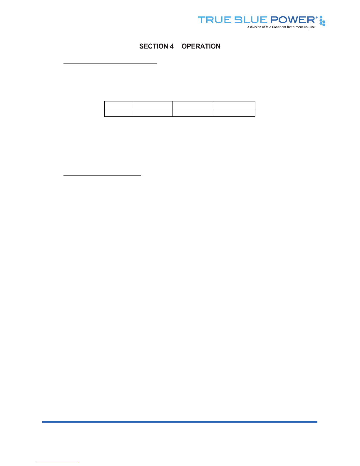
4.1 ELECTRICAL PERFORMANCE
The TC2000 Series Static Converter converts an alternating current (AC) voltage input to a
regulated VDC output. See Table 4.1 specific output and input frequency.
Model Input Frequency Output
TC2000 115 VAC 360-800 Hz 28 VDC
Table 4.1
TC2000 Series Electrical Performance
The unit is capable of providing 2000 watts to power a variety of aircraft accessories including
lights and onboard systems.
4.2 PROTECTIVE FEATURES
4.2.1 Remote On/Off
The TC2000 Series Static Converter incorporates a remote on/off feature that allows
the user to enable or disable the output of the unit. By providing a ground on the
appropriate pin (See Table 3.3) the user, via a remote mounted switch, can enable
the output of the unit. The unit can be similarly disabled by removing the ground
signal (open circuit) to the same pin.
4.2.2 Over-Temperature
The TC2000 Series Static Converter incorporates an internal temperature sensing
device that continually provides monitoring and feedback to the control circuits.
When the unit senses an internal condition that exceeds maximum temperature
ratings, the output is disabled and the internal cooling fans cease to operate. The
unit output will be enabled when the temperature returns to within acceptable limits.
This over-temperature reset occurs automatically without external intervention
required.
4.2.3 Short Circuit and Over-Current
The TC2000 Series Static Converter is capable of surviving a short circuit or over-
current event without permanent damage or effect to long-term reliability. Under
standard conditions, the unit can provide over its rated power output up to 2200
watts for over 5 minutes (until over-temperature shutdown occurs).
Rev C, March 8, 2018 15 Manual Number 9019049
5.1 INSTRUCTIONS FOR CONTINUED AIRWORTHINESS
No periodic scheduled maintenance or calibration is necessary for continued airworthiness of
the TC2000 Series Static Converter. If the unit fails to perform to specifications, the unit must be
removed and serviced by Mid-Continent Instruments and Avionics or their authorized designee.
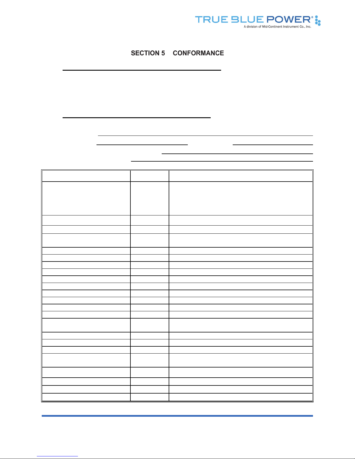
5.2 ENVIRONMENTAL QUALIFICATION STATEMENT
NOMENCLATURE:
Static Electrical Power Converter
MODEL NUMBER:
TC2000
TSO NUMBER:
C71
MANUFACTURERS SPECIFICATIONS:
Test Specification (TS) 714, Test Data Sheet (TDS) 714
QUALIFICATION STANDARD:
RTCA DO-160G
CONDITIONS SECTION DESCRIPTION OF TEST
Temperature and Altitude
Low Temperature
High Temperature
Altitude
4
4.5.2
4.5.4
4.6.1
Category C3
Operating Low Temp = -55C
Operating High Temp = +70C
Altitude = +35,000 ft.
Temperature Variation 5 Category S2
Humidity 6 Category B
Operational Shock and
Crash Safety 7 Category B
Vibration 8 Category R; Curve C, C1 [(RCC1)]
Explosion 9 Category X
Waterproofness 10 Category X
Fluids 11 Category X
Sand and Dust 12 Category X
Fungus 13 Category X
Salt Spray 14 Category X
Magnetic Effect 15 Category A
Power Input 16 Category A(CF)
Voltage Spike 17 Category A
Audio Frequency Conducted
Susceptibility 18 Category R(CF)
Induced Signal Susceptibility 19 Category X
Radio Frequency Susceptibility 20 Category X
Emission of Radio Freq Energy 21 Category B
Lightning Induced Transient
Susceptibility 22 Category X
Lightning Direct Effects 23 Category X
Icing 24 Category X
ESD 25 Category A
Flammability 26 Category X
Table of contents
Other True blue power Media Converter manuals


