TRUE MODS PIM-00000173-V002 User manual
NOTE: The bracket can be successfully mounted in several ways, with the included
screws, machine screws and bolts, self-tapping screws, or heavy-duty double sided
tape. Machine screws and bolts, self-tapping screws, or heavy-duty double-sided
tape are to be supplied by the installer.
SPST ON/OFF Switch Box
•
•
www.truemods.com
US Toll Free: 1-855-533-6654
International: 1-909-212-0993
Fax: (909) 575-6722
E-mail: [email protected]
True Mods © 2012-2021 All Rights Reserved
apply adhesive for maximum adhesion.
Do not install this product or route any wires in the deployment area of your air bag. Equipment
mounted or located in the air bag deployment area will damage or reduce the eectiveness of the
air bag, or become a projectile that could cause serious personal injury or death. Refer to your
vehicle owner’s manual for the air bag deployment area. The User/Installer assumes full
responsibility to determine proper mounting location, based on providing ultimate safety to all
passengers inside the vehicle.
Do not attempt to activate or control this device in a hazardous driving situation.
IMPORTANT: READ CAREFULLY BEFORE ASSEMBLY AND USE.
•
•
•
Proper installation of this product requires the installer to have a good understanding of
automotive electronics, systems, and procedures.
If mounting this product requires drilling holes, the installer MUST be sure that no vehicle
components or other vital parts could be damaged by the drilling process. Check both sides of
the mounting surface before drilling begins. Also de-burr any holes and remove any metal shards
or remnants. Install grommets into all wire passage holes.
If this manual states that this product may be mounted with suction cups, magnets, tape or
Velcro®, clean the mounting surface and dry thoroughly prior to
Manual ID: PIM-00000173-V002
Installation:
CAUTION! When drilling it is absolutely necessary to ensure that no other
components or wiring will be damaged. Always check both sides of the mounting
surface. If damage is likely, select a dierent mounting location.

Using the Included Screws
Machine Screw and Bolt Method (user supplied)
NOTE: This method is very secure but only works if you have access to the back
side of the mounting surface.
Using Self-Tapping Screws (user supplied)
NOTE: This method is most eective when mounting to a metal surface. If
mounting to plastic the screws may loosen over time. Also, a power drill/driver
must be used to install self-tapping screws.
Using Double-Sided Tape (user supplied)
Use a drill bit slightly smaller than the screws and drill out the previously
marked holes.
Reposition mounting bracket over holes and attach with the two screws.
Use a drill bit slightly larger than the machine screw and drill out the two
previously marked holes.
Use a machine screw, two washers, a lock washer, and a nut in each hole to
attach the bracket.
Temporarily attach the bracket to the mounting location with tape.
Use two self-tapping screws to attach the bracket to the mounting surface.
Remove tape.
Position bracket on mounting surface and mark location.
Thoroughly clean the bracket and the mounting surface with water and/or
mild soap.
Attach double-sided tape to the bracket and double check the mounting
location.
Attach the bracket to the mounting surface.
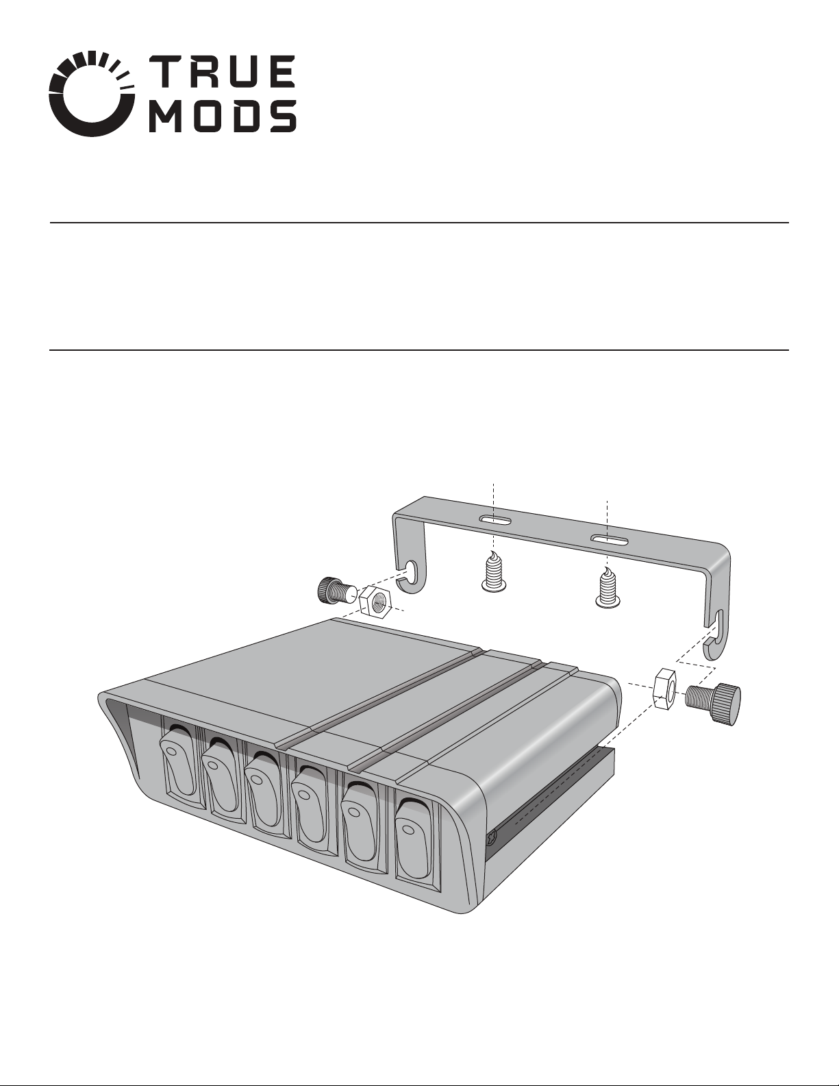
Thread the included nuts a few turns onto the thumb screw/bolt.
Slide one nut/bolt assembly into the channel on the side of the box.
Repeat on the other side with the other nut/bolt assembly.
Position the box in the bracket so that the nuts/bolts drop into each side of the
bracket.
Position switch box and tighten both thumb screw/bolt.
Step 2: Attaching Switch Box to the Bracket
Input Voltage: 12V DC
Input Current: 4 Switch Model - 15A MAX Per Switch/20A MAX Per Box
6 Switch Model - 15A MAX Per Switch/40A MAX Per Box
WARNING! All customer supplied wires that connect to the positive terminal of
the battery must be sized to supply at least 125% of the maximum operating
current. The addition of fuses as close to the positive post of the battery and
between the accessories and the switch box are recommended.
- Positive battery power in.
- Chassis ground for the box only. (for LED indicator lights on switches)
- Power from switch “A” out to accessory.
- Power from switch “B” out to accessory.
- Power from switch “C” out to accessory.
- Power from switch “D” out to accessory.
- Power from switch “E” out to accessory. (6 switch model only)
- Power from switch “F” out to accessory. (6 switch model only)
RED
BLACK
BROWN
ORANGE
YELLOW
GREEN
BLUE
PURPLE
1.
2.
3.
4.
5.
Position the bracket over the desired mounting location.
Mark the position of the two screw holes.
Determine the desired mounting method.
Step 1: Mounting the Bracket
1.
2.
3.
a.
b.
c.
d.
i.
ii.
i.
ii.
i.
ii.
iii.
i.
ii.
iii.
iv.
True Mods © 2012-2021 All Rights Reserved
Specications:
Wiring:
Wiring Diagram:
To Ground To Ground
Switch Box (4 Switch Model)
REDRED
BLACK
BLACK
GREEN - SWITCH D
GREEN - SWITCH D
YELLOW - SWITCH C
YELLOW - SWITCH C
ORANGE - SWITCH B
ORANGE - SWITCH B
BROWN - SWITCH A
BROWN - SWITCH A
Accessory 4
Accessory 4
Accessory 3
Accessory 3
Accessory 2
Accessory 2
Accessory 1
Accessory 1
Battery
+
-
To Ground

To test continuity: With your DMM set to read ohms Ω, probe the negative
battery terminal and the potential grounding location. If the DMM reads less
than .5 ohms you have found a good grounding location.
In the above example, the brown wire would run to the power wire of the 36”
light bar, the orange wire would run to the fog lights, the yellow wire would run
to the oodlights, and the green wire would run to the rock lights.
It is also worth mentioning that the switch box does contain a 20 amp fuse,
however, it would also be a good idea to install a fuse in the wire between each
switch and accessory if they are not already equipped with one.
True Mods © 2012-2021 All Rights Reserved
Attach the red wire(s) directly to positive battery power. The easiest way to do this
is by wiring directly to the battery or the positive post on the fuse box.
Attach the black wire(s) to ground. The best way to do this is by wiring to an
existing ground bolt or stud. If this is not possible, the wire can be attached to a
clean, paint-free metal surface that has continuity to the ground terminal on the
battery.
Run each colored wire to the power wires of the accessories you wish to control.
Attach each accessories ground wire to a suitable ground. See step 2 for
information regarding the selection of an appropriate ground location.
Test your new switch box and enjoy!
#1: Low Amperage Wiring
When the total amp draw from all your accessories is less than 20 amps and no
accessory draws more than 15 amps.
#2: High Amperage Wiring
When the total draw from all your accessories is 20 or more amps or one of the
accessories pulls 15 or more amps.
Here, the total amperage is right at the rated capacity of the switch box. In this
situation, it is likely that the 20 amp fuse would fail on a regular basis.
OR
Here the 44” light bar is operating at 15 amps, right at the maximum rating of the
switches in the box. This is a potentially dangerous situation that will cause a
premature failure of the switch.
In both cases a relay is needed to reduce the amperage load on the box and switches.
Switch
A
B
C
D
Total
Accessory
44” Light Bar
6.5” Spot Light
6.5” Flood Light
6.5” Flood Light
Amp Draw
15
2
2
2
Number of Units
1
2
2
2
Total Amp Draw
15
4
4
4
27
1.
2.
3.
4.
5.
Example:
Switch
A
B
C
D
Total
Accessory
36” Light Bar
4” Fog Light
6.5” Flood Light
Rock Light
Amp Draw
7
1
2
0.4
Number of Units
1
2
4
6
Total Amp Draw
7
2
8
2.4
19.4
Switch
A
B
C
D
Total
Accessory
36” Light Bar
6.5” Spot Light
12” Flood Light
6.5” Flood Light
Amp Draw
7
2
5
2
Number of Units
1
2
1
2
Total Amp Draw
7
4
5
4
20
To GroundTo Ground
Switch Box (6 Switch Model)
Accessory 1Accessory 1
YELLOW - SWITCH CYELLOW - SWITCH C
ORANGE - SWITCH B
ORANGE - SWITCH B
BROWN - SWITCH A
BROWN - SWITCH A
PURPLE - SWITCH FPURPLE - SWITCH F
BLUE - SWITCH E
BLUE - SWITCH E
GREEN - SWITCH D
GREEN - SWITCH D
Accessory 3
Accessory 3
Accessory 2
Accessory 2
Accessory 4Accessory 4
Accessory 6
Accessory 6
Accessory 5
Accessory 5 REDRED
BLACK
BLACK
RED
RED
To Ground To GroundBattery
+
-
a.
a.
b.

A relay is an electromechanical device that allows a large electrical load to be
controlled by a separate, much smaller load.
A relay is composed of two separate electrical circuits. The rst circuit is
composed of a terminal that allows power in from a switch, an electromagnetic
coil, and a terminal to ground the coil. The second circuit is composed of a
terminal connected to battery power, a movable armature, a set of contacts, and
a terminal wired to your accessory.
When low current, controlled by a switch, ows through the coil side of the
relay, the coil is magnetized, the armature is pulled down, the contacts make a
connection, and high current is allowed to ow from the battery to the accesso-
ry.
Once the switch is turned o, current stops owing through the coil, a spring
returns the armature to its original position, and current is cut o to the
accessory.
Reduces load on OEM components.
Larger loads than normal can be controlled by the switch as the switch never
physically interacts with the larger load side of the relay.
Heavy duty switches are not needed since only a small amount of current is
required to energize the relay coil.
It is easier to use the correct gauge wire.
It is easier to control multiple accessories with a single switch.
One of the most common types of relays is the 5-pin Bosch style relay. This is
an example of the pin layout and function of a Bosch Style relay.
In this case, pins 85 and 86 are the low current coil circuit and pins 30 and 87 are
the high current accessory circuit. In this situation we will be ignoring 87a.
A typical Wiring setup would look like this:
Two relays will be needed.
Each relay will be connected to the same ACC power source, ground, and
positive post of battery.
But each relay (Pin 87) will need to be wired to a dierent red wire on the
switch box.
i.
ii.
iii.
If you want your switch box and accessories to function only when the car/ignition is
on, a relay will need to be placed between the battery and the switch box. You will be
using ACC/ignition power to trigger the relay which will then supply power from the
battery to the switch box.
Find an acceptable location to tap into ACC/ignition power (powered only when
the car/ignition is on).
Using a Bosch style relay, wire:
1.
2.
To correctly wire a Bosh style relay rst begin with steps one and two of the low
amperage wiring procedure.
Then wire the correctly colored wire from the switch box to pin 86 on the relay.
For example, if you want to control a light bar with switch A, you would connect
to brown wire to this terminal.
Connect pin 85 to ground.
Next, wire battery power to pin 30. It is a good idea to put a fuse in this wire.
Now run a wire from pin 87 to your accessory.
Finally, attach your accessories ground wire to any acceptable ground.
The best place to borrow power from is an unused ACC fuse terminal in the fuse
box.
If this is not available, an ACC fuse like the horn, cigarette lighter, or radio fuse
can be piggybacked with a fuse tap.
Pin 86 to ACC power.
Pin 85 to ground.
Pin 87 directly to the red wire on the switch box.
Pin 30 to positive post of battery.
If using part ACCEPSSWH0082 (model with 6 switches):
d.
e.
f.
g.
h.
i.
a.
b.
a.
b.
c.
d.
e.
A Brief Discussion of Relays:
What is a relay?
How a relay works.
Benets of a relay.
How to wire a relay.
NOTE: Relays come in many dierent shapes, sizes, and congurations. Always
verify pin location, function, and t of any relay you are planning to use.
1.
2.
3.
4.
a.
b.
a.
b.
a.
b.
c.
d.
e.
a.
b.
c.
True Mods © 2012-2021 All Rights Reserved
Optional Wiring:
87
87a
86
30
85
+
+
86
85 30
87a 87
Normally OFF Relay with a Positive Trigger
87
87a
86
30
85
DeviceDevice
To GroundTo Ground
To Positive
Trigger Source
To Positive
Trigger Source
To GroundTo Ground
To GroundTo Ground
FUSE
CUSTOMER’S SUPPLY
Leave DisconnectedLeave Disconnected
+
Battery
Popular Switch manuals by other brands


Cabletron Systems
Cabletron Systems SmartSTACK EPIM1000-S1LX 1000BASE-LX Quick installation guide

Johnson Controls
Johnson Controls exacqVision G Series quick start guide

steute
steute ZS 80 Mounting and wiring instructions

Kramer
Kramer VS-211XS quick start guide

NTI
NTI ENVIROMUX Series Installation and operation manual

Dell
Dell MXL 10GbE reference guide


