True 10RStager Quick start guide

10RStager Installation and Operational Manual 10R80 Transmissions Rev C
Note: The following instructions are for 8 cylinder 10R80 Automatic Transmission installations for 2018 and
newer model years. Contact True Motorsports for other 10R80 configurations.
This manual will outline the wiring of the 10RStager. Ensure that each connection is a reliable connection that
will not cause any intermittent behavior on the signals. For power connections to the 10RStager, ensure that
the power source is a switched ignition source that powers up when you key on and that it has an appropriately
sized fuse for the circuits connected. The 10RStager consumes less than 0.5 Amps during operation.
The 10RStager must be wired per the instructions outlined in this document and is designed to work for first
gear and second gear launch setups. The wiring for the second gear Transbrake is slightly different than the
first gear and also requires an ECU tune that enables second gear launches. The 10RStager will not operate
without interfacing to the transmission and brake pedal wiring. The brake pedal wiring must be wired to prevent
accidental engagement of the transbrake. Note that the foot brake pedal must be engaged prior to pressing the
Transbrake button to engage the Transbrake.
Perform the installation in the following order:
1. Turn the ignition off, open the hood and disconnect the battery. Locate the vehicle PCM (Powertrain
Control Module). This should be under the hood near the front passenger side.
2. Locate and install the 10RStager control box in a location that is within the cab of the vehicle. Do not
locate this device in the engine bay. Follow the wiring diagram instructions below and on the following
pages. When wiring up this device, ensure that best practices are followed while wiring up the
10RStager. It is recommended that each connection be soldered and heat shrink applied.
3. The instructions for wiring the 10RStager will be outlined on the following pages. The diagram shown
on pages 2 and 3 should be used as an overall system wiring diagram. Follow the instructions outlined
in item 4 below, to wire the 10RStager per the following wiring diagrams:
Page 1

FIRST GEAR - 10R80 Wiring Diagram reference for the 10RStager
● Cut the SSF wire (Blue/Grey) and connect the Dark Blue Wire to the PCM side
● Cut the SSC wire (Grey/Orange) and connect the Grey Wire to the PCM side
● Cut the SSB wire (Green/Brown) and connect the Light Green Wire to the PCM side
● Connect the Pink Wire to the Brake Pedal Position Switch Signal wire (Violet/White)
● Connect the White Wire to the Brake Pedal Position Switch Power wire (Green/Red)
● Connect the Tan Wire to the SSF wire (Blue/Grey) that is connected to the 10R80
● Connect the Orange Wire to the SSC wire (Grey/Orange) that is connected to the 10R80
● Connect the Yellow Wire to the SSB wire (Green/Brown) that is connected to the 10R80
Note: The signal at the light blue wire can be used to initialize a 2-step or other devices. If a 2-step interface is
needed, attach to the light blue wire after the Transbrake Enable button. If the 2-step interface requires a low
signal input a relay may need to be used and the light blue wire connection can be used to trigger the relay.
Page 2

SECOND GEAR - 10R80 Wiring Diagram reference for the 10RStager
● Cut the SSF wire (Blue/Grey) and connect the Dark Blue Wire to the PCM side
● Cut the SSB wire (Green/Brown) and connect the Light Green Wire to the PCM side
● Connect the Pink Wire to the Brake Pedal Position Switch Signal wire (Violet/White)
● Connect the White Wire to the Brake Pedal Position Switch Power wire (Green/Red)
● Connect the Tan Wire to the SSF wire (Blue/Grey) that is connected to the 10R80
● Connect the Yellow Wire to the SSB wire (Green/Brown) that is connected to the 10R80
Page 3

4. Locate the PCM which is located on the right side of the engine. Disconnect the Top PCM connector.
Run six wires with SSB, SSC and SSF as part of the naming convention out to the PCM/Transmission
connector located in the engine compartment. Run through the passenger side firewall grommet.
Page 4

5. On the PCM connector, remove at least 6-8 inches of the black tape so that you can access the wires.
Page 5

6. Identify the SSF, SSC, and SSB solenoid wires so that the 10RStager can be inserted into this
interface.
FIRST GEAR ONLY
Page 6

SECOND GEAR ONLY
The SSB, SSC(first gear only) and SSF signals will pass through the 10RStager during normal operation.
When the Transbrake is activated, the 10RStager will manipulate the solenoids to create a Transbrake.
Page 7

7. Locate the Brake Pedal Position (BPP) Switch under the driver side dash.
Connect the white wire from the 10RStager to the Green/Red wire on Pin 1 of the BPP Switch. This
should be a Y or T configuration so that signals are not interrupted. Reference the image below to
ensure assist with referencing the wires. Ensure that the wire maintains connection with Pin 1 as well
as the PCM/BCM connection. Next, connect the Pink wire to Violet/White wire on Pin 4 of the BPP
Switch as shown below. This should be a Y or T configuration so that signals are not interrupted.
BPP Switch Interface Wiring Diagram
8. On the 10RStager wire harness, connect the Red power wire to a switched 12V power source so that it
will only turn ON when Ignition Power is applied or when a dedicated switch is used. The 10RStager
consumes less than 0.5 Amps of current while under maximum load. Connect the Black wire to a clean
battery ground connection, as a poor chassis ground connection could damage the electronics or result
in inadequate performance. The Tranbrake enable (Lt Blue) and Stage enable (Violet) buttons should
be wired so that the 10RStager will see a high voltage when the buttons are depressed. Any 2-step
interfaces should be connected to the Light Blue wire connection or the Pink Brake Pedal interface
wire.
Refer to the Operators Manual on the following page for adjusting settings and tune modification
requirements.
Page 8

10RStager Operator's Manual
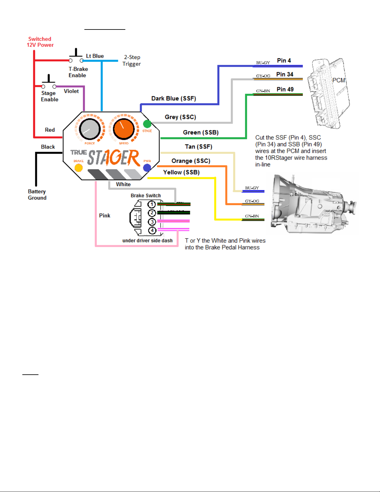
The 10RStager requires two input buttons for operation. Each input must be pulled above 10 volts to become
active. The first input button will activate the Transbrake on the 10R80. The foot brake pedal on the vehicle
must be depressed before the Transbrake will engage, as this is designed so that the Transbrake will not be
accidentally depressed. Once the Transbrake has been enabled on the vehicle, the foot brake can be released.
If the system is working, the brake lights will remain on while the Transbrake button is depressed.
To use the Stage button, the Transbrake button must be depressed and engaged prior to the Stage Button
being depressed. Holding or tapping the Stage button while also holding the Transbrake button will enable the
vehicle to creep forward slowly by momentarily disengaging the Transbrake. Use this Stage button to move
from the Pre-stage to the Staging beams. The LED indicators on the front of the unit should be used to know
the state of the inputs and the Transbrake state. When staging, the brake LED may pulse to let the user know
that the smooth staging algorithm is engaged. When ready to launch, release the Transbrake button.
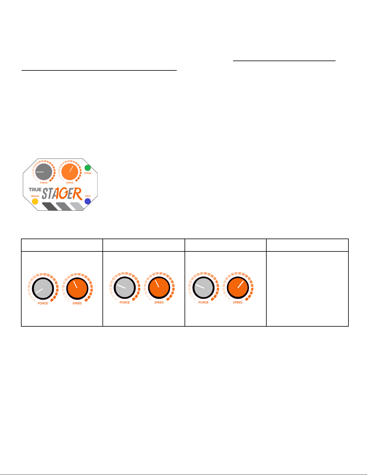
Below is a guide to assist you in finding the best settings for your vehicle.
Step 1: Start with the Force to the 7 o’clock position and Speed near the 10 o’clock position.
Step 1
Step 2
Step 3
Step 4
Set Speed to 11 o’clock and
Force to 7 o’clock
Press and hold the Bump
Button
If NO movement,Increase the
Force 1 click
Press and hold the Bump
Button
If NO movement, set Speed to
2 o’clock.
Press and hold the Bump
Button
If NO movement after Step 3,
repeat Step 2 and Step 3 until
movement is present.
Use the Speed knob to fine
tune the vehicle speed while
staging
Speed = Vehicle creep speed Force = Transbrake release power
NOTE: If the vehicle continues to roll forward after the bump, this is an indicator that your Transbrake is unable
to grab and stop the vehicle from moving forward for the launch horsepower level. This could be an indicator
of a worn clutch within the transmission or a trouble code. Consult a 10R80 Transmission expert to see if this
Transbrake will hold at the power level that you are operating at or if something could be causing the code.
The 10RStager requires an experienced Tuner that can disable codes in the calibration. At a minimum the
following codes must be disabled: P0758, P0763, P2709, P097C, P097B, P097F
Depending on your setup, other disabled codes may be required. Please consult with an experienced Tuner
Page 9
Other True Automobile Accessories manuals
Popular Automobile Accessories manuals by other brands

Thule
Thule 121 Mounting & installation

VBG
VBG Onspot Mounting instruction/Spare Parts List

SEON
SEON RVM-TLHD installation guide

LaserLine
LaserLine 921K operating instructions

Douglas Dynamics
Douglas Dynamics BLIZZARD SPEEDWING 760SW Installation instructions & owner's manual

Southwing
Southwing SH-650 user guide