Trueful Electronics C3V Series User manual
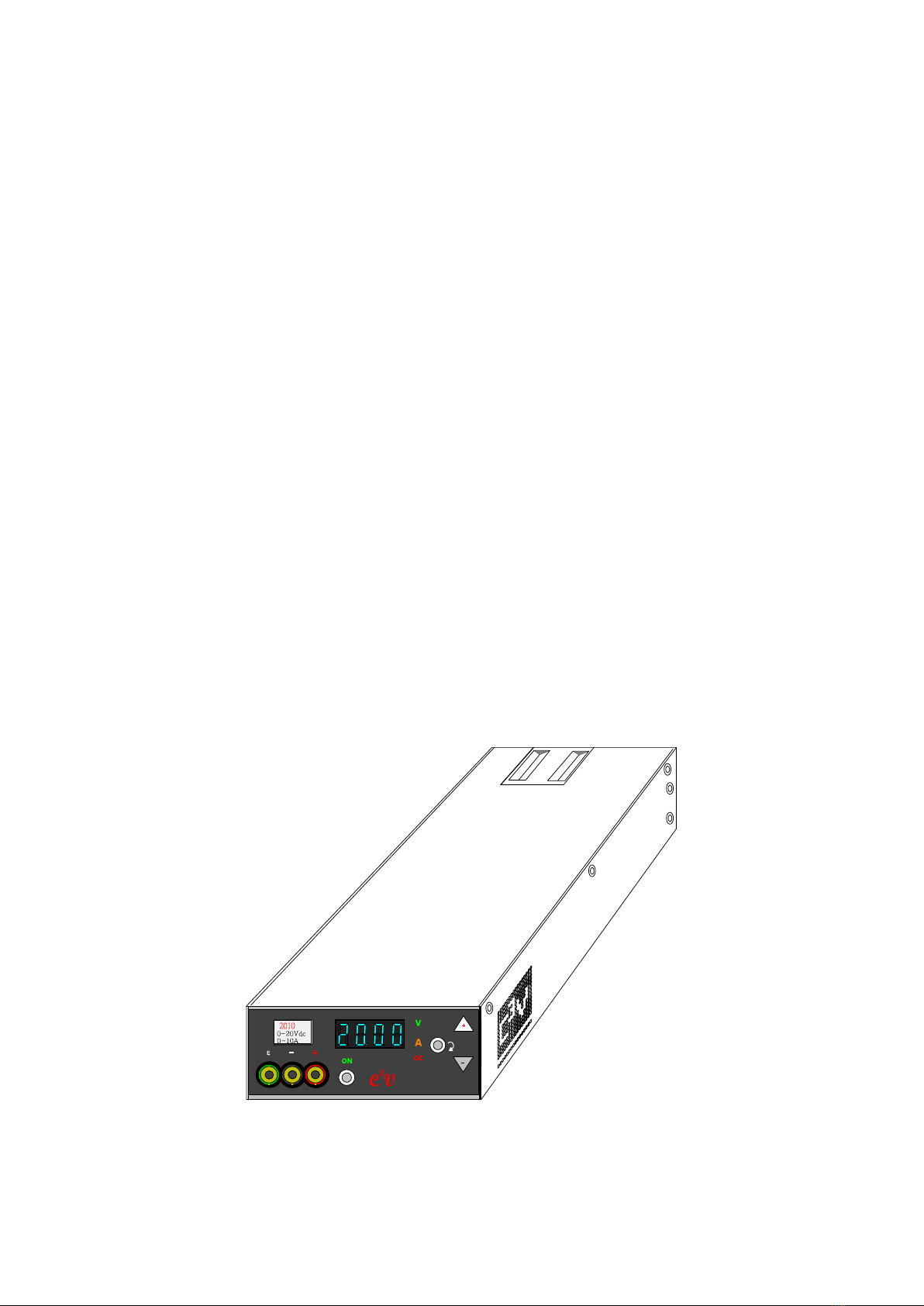
C³V Series
2010 4005 6003
Programmable DC Power Supply

P.2
1. Important Safety Instructions --------------------------------------- p. 4
1.1 General
1.2 Symbols & Messages
1.3 Safety Instructions
1.3.1 Transportation
1.3.2 Ambient Conditions
1.3.3 Installation
1.3.4 Operation
1.3.5 Service & Maintenance
1.3.6 Storage
2. Get Acquainted with the C³V ----------------------------------------- p. 7
2.1 Front Panel Overview
2.2 Models & Output Ratings
3. Operation ------------------------------------------------------------------- p. 9
3.1 General
3.2 Description
3.3 Output (Reading) Mode & Setting Mode
3.4 Switching between Two Modes
4. Keys: Special Functions --------------------------------------------- p. 12
4.1 Normal Operations
4.2 Special Functions
4.3 Default Output State
5. C³V Series Communication Interfaces --------------------------- p. 14
5.1 Communication Data Rate
5.2 C³V Series with RS232 Interface
5.2.1 RS232 Connection to PC
5.3 C³V Series with USB Interface
5.4 C³V Series with RS485 Interface
5.4.1 RS485 Termination Resistor Installation & Wiring
5.4.2 RS485 Address Settings

P.3
6. C³V Series Communication Protocol ----------------------------- p. 17
6.1 Communication between PC and C³V Series
6.2 Message Terminator of Protocol: CR LF
6.3 Data Format (PC to C³V Series)
6.3.1 ADDR (PC to C³V Series)
7. Automatic Fan Speed vs Temperature Control --------------- p. 23
7.1 PWM Fan Speed Control
7.2 Over Temperature Protection (OTP) Alarm
8. C³V Series Wiring and Connections ------------------------------- p. 24
8.1 All Connections
8.2 Special Connector to Prepare
8.3 Wire Size Table
8.4 Type of Panel Layouts
9. Mounting and Ventilation -------------------------------------------- p. 27
9.1 Flat Mount
9.2 Erect Mount
10. C³V Series Specifications ------------------------------------------- p. 29
11. Appendix ------------------------------------------------------------------ p. 31
P.4
1. Important Safety Instructions
1.1 General
This chapter contains important safety instructions for fully utilizing the C3V Series DC
Power Supply. It is important that this manual is read and understood by all persons
prior to transporting, installing, operating, servicing, or maintaining the product.
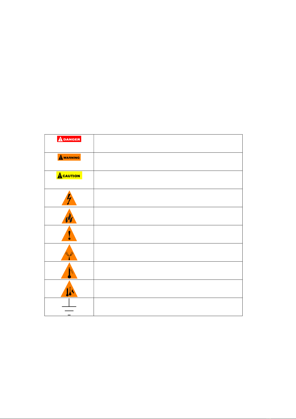
1.2 Symbols & Messages
The following symbols mainly appear in this chapter and may be found in other
chapters and on the product itself.
Indicates an imminently hazardous situation which, if not
avoided, will result in death or serious injury
Indicates a potentially hazardous situation which, if not
avoided, may result in death or serious injury
Indicates a potentially hazardous situation which, if not
avoided, may result in moderate or minor injury
Electrical shock risk
Fire risk
Attention
EMI risk
High temperature
Condensation
Earth terminal
1.3 Safety Instructions
1.3.1 Transportation
When transporting the product, please ensure that the original packaging is used to
prevent damage to the product.
P.5
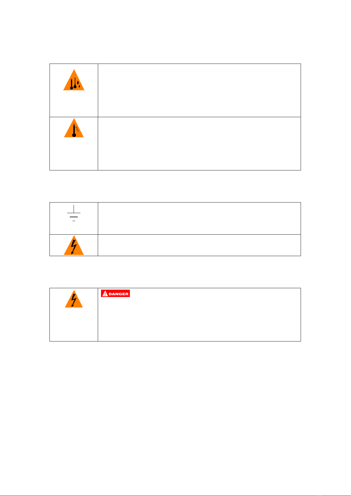
1.3.2 Ambient Conditions
The product is designed for indoor use.
Condensation may occur after the product was shipped, or
subject to a sudden change in an atmosphere of temperature or
humidity. Do not use the product for at least two hours to
ensure it is dry before turning it on.
Do not place the product in high humidity area.
Do not expose the product to direct sunlight or any heat source.
Do not block the ventilation openings at the enclosure of the
product.
Do not place any heavy objects on the product.
1.3.3 Installation
The product is constructed to Protection Class I. Connect the product
to an earthed wall receptacle with a power cord approved by relevant
International Standards.
The product is rated at AC input 85~264V, 47~63Hz mains.
1.3.4 Operation
Be careful! A change from open circuit to short circuit could result in
high current sparks and cause injury to eyes. An instantaneous
power circuit change from short to open may induce high voltage and
arcing, causing shock and injury to eyes.

P.6
1.3.5 Service & Maintenance
The product operates at hazardous high voltage (near DC 380V or
AC 267V). Only qualified personnel can carry out servicing or
maintenance.
Always use a properly rated voltage sensing device to confirm that all
power is off.
Before attempting any service, disconnect the product from all power
supply and ensure that no harmful residual voltage remains at the
terminals of bulk capacitors.
Replace the fuse only with the same amperage and voltage ratings
to avoid risk of fire.
This is a Class A device which may cause RF interference
within the home.
The product should only be operated when the case is securely
closed, with all screwed tightened.
While operating the product, the wearing of metal or other
conducting jewelry such as chains, bracelets, rings, etc. is not
recommended.
1.3.6. Storage
Location: Indoor
Relative Humidity: <80%
Temperature: -10℃ ~ 70 ℃

P.7
2. Get Acquainted with C³V Series
2.1 Front Panel Overview
Panel display:
1 Display Meter
4-digit meter displays voltage, current and internal
temperature of the product.
For auxiliary uses of system parameters setup.
2 Output key Turns the output on/off.
3 Enter key Circulatory mode selection. Up/Down inputs confirmation.
4 Up key Input increments.
5 Down key Input decrements.
6 V-LED
Green “V” denotes unit = ”VOLT” for meter display.
Lit state: Meter display in Output (Reading) mode.
Blinking: Meter display in Setting mode.
7 A-LED
Orange “A” denotes unit = ”AMPERE” for meter
display.
Lit state: Meter display in Output (Reading) mode.
Blinking: Meter display in Setting mode.
8 cc-LED
Red “cc” symbol.
Off state: Output in constant voltage (CV) mode.
Lit state: Output in constant current (CC) mode.

P.8
9 Output LED
Green “ON” symbol.
Off: Output Off.
Lit: Output On.
10 Output terminals Ground terminal, negative terminal, and positive
terminal, respectively.
11 Model & output
ratings See 2.2
2.2 Models & Output Ratings
C³V series consists of 3 models and ratings as listed below:
Model 2010 4005 6003
Voltage 0 - 20V 0 - 40V 0 - 60V
Current 0 - 10A 0 - 5A 0 - 3.5A
Power 200W 200W 210W
P.9
3. Operation
3.1 General
C³V Series integrates two power supplies – constant voltage (CV) and constant
current (CC). These two power supplies exclusively operate, and outputs do not
exceed user-preset limit. CV or CC states are dependent on and limited by the
comparison between load conditions and C³V Series settings.
3.2 Description
C³V Series utilizes the Up and Down keys to set desired voltage and current outputs.
Real time voltage and current are displayed on the Display Meter. Pressing the Enter
key momentarily switches between different operation modes.
The V-LED and A-LED indicate the selected operation mode. The CC-LED indicates
that the power supply currently being in CC Output (Reading) mode.
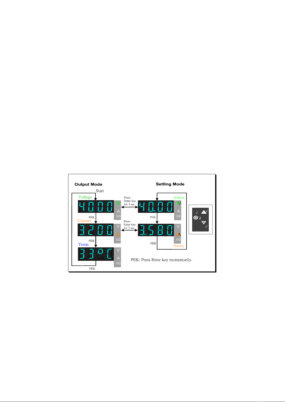
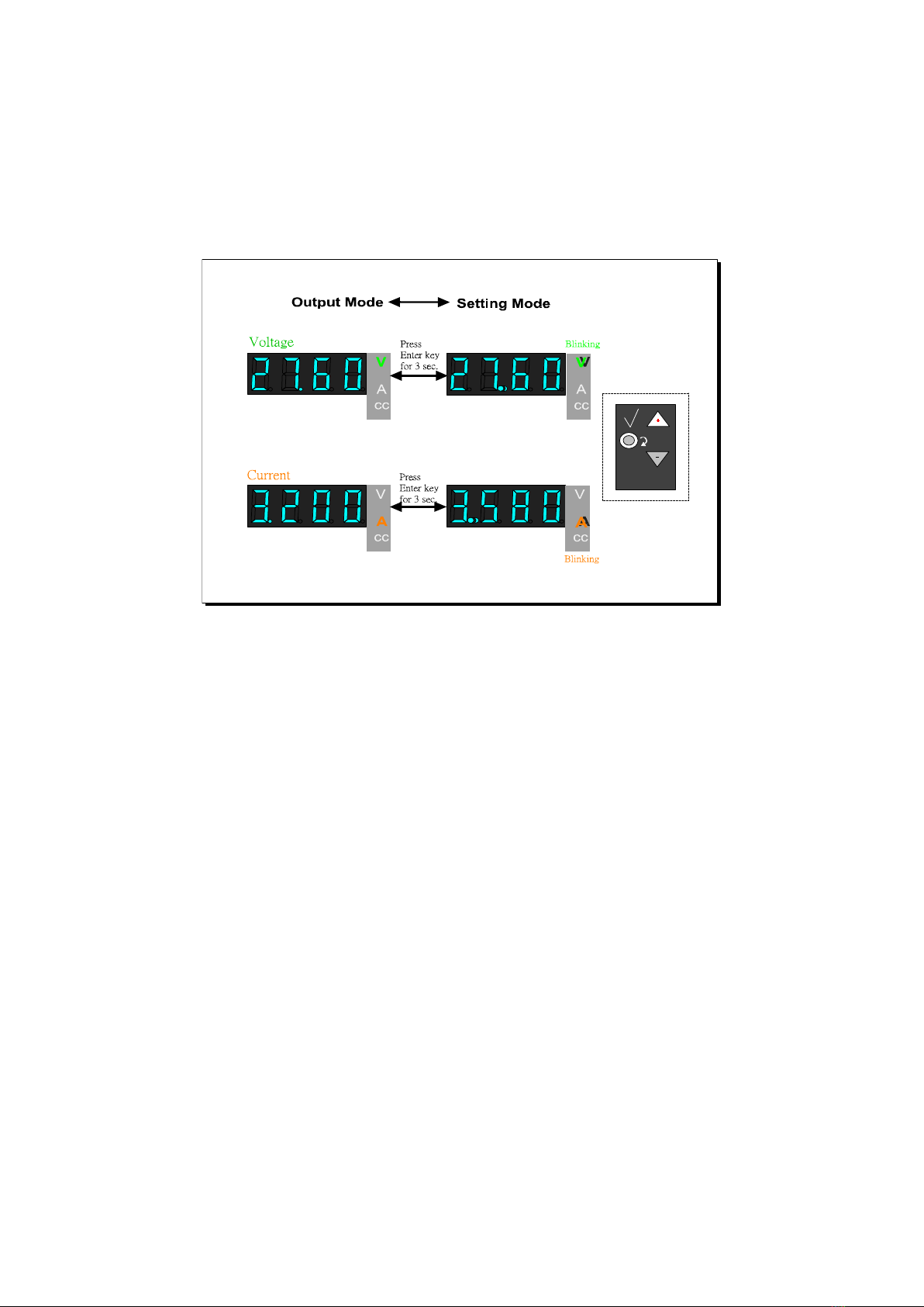
3.3 Output (Reading) Mode & Setting mode
Output (Reading) Mode
Upon AC powering on the C³V Series, the unit automatically enters “Output (Reading)
Mode” and the green V-LED illuminates. The values shown on the Display Meter refer
to the last used data. Pressing the Enter key momentarily, you can read the voltage,
current (if a load was connected) and internal temperature. The outputs are controlled
by preset CC and CV values, as shown in the graph below.

P.10
Setting Mode
By pressing the Enter key for 3 seconds, you will hear a short beeping sound. This
indicates that the C³V Series has entered “Setting Mode”. “The V-LED OR A-LED
“ AND “ the respective decimal point ” will be blinking on the 4-digit Display Meter.
Use the Up or Down keys to set the desired voltage or current. Press the Enter key for
3 seconds to confirm. The C³V Series now reverts to “Output (Reading) Mode”. The
adjusted value is displayed in the graph below.
P.11
3.4 Switching between Two Modes
Press the Enter key for 3 seconds to switch between Output (Reading) Mode and
Setting Mode. This operation is especially useful for circuit experiments where
frequent changes of V or A is necessary.

P.12
4. Keys: Special Functions
Some keys are programmed with special functions.
4.1 Normal Operations
Output key
Press to toggle the output on / off (refer to 4.3 for default
AC power setting).
Enter key
Press for 3 seconds to select between Output (Reading)
Mode and Setting Mode.
Momentary press to select V or A.
Please refer to V-LED and A–LED on the panel.
Up key
Momentary press for least digit increment.
Press and hold for larger digit increment (larger and faster
increment).
Please refer to the Display Meter on the panel.
Down key
Momentary press gets least digit decrement.
Press and hold to get larger digit decrement (more and
faster decrement).
Please refer to the Display Meter on the panel.
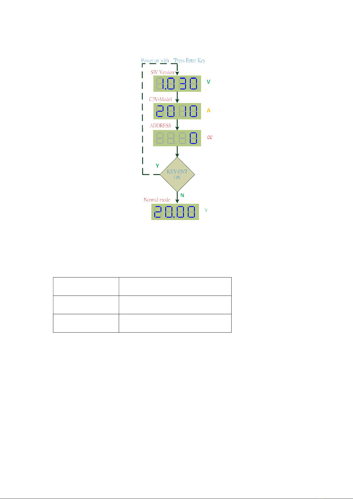
4.2 Special Functions
Query on firmware version / model
number / RS-485 address
Hold down the Enter key and turn on AC
power. You will find:
V-LED: firmware version
A-LED: model number
CC-LED: RS-485 address
Release the Enter key to resume normal
operations. Refer to the graphic below.
Set up RS-485 address
Press and hold the Output key for 10
seconds until it beeps. The LED will display
the address. Press the Up and Down key to
set the address and press the Enter key to
confirm.
P.13
4.3 Default Output State (ON / OFF)
Output state when the unit is powered on:
JP7 on MCU card Default state at AC power on
OPEN Output OFF
SHORT Output ON
Note: User modification not recommended.
P.14
5. C³V Series Communication Interfaces
C³V Series provides three isolated communication interfaces: RS232, USB and
RS485.The selected interface must be confirmed before shipping and cannot be
modified after delivery.
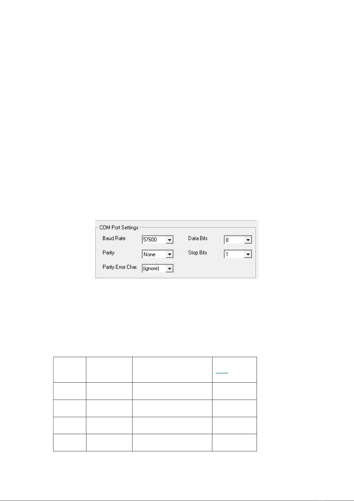
5.1 Communication Data Rate
Data rate: 57600/N/8/1
■ Baud Rate: 57600
■ Parity: None
■ Data Bit: 8
■ Stop Bit: 1
■ Flow Control: None
5.2 C³V Series with RS232 Interface
Uses standard female DB9 connector.
RS232 pin assignment:
Pin No. Signal Name Description DTE In/Out
1 DCD Data Carrier Detect Input
2 RX Receive Data Input
3 TX Transmit Data Output
4 DTR Data Terminal Ready Output

P.15
5 SGND Signal Ground -
6 DSR Data Set Ready Input
7 RTS Request To Send Output
8 CTS Clear To Send Input
9 RI Ring Indicator Input
5.2.1 RS232 Connection with PC
5.3 C³V Series with USB Interface
USB Type B Connector as shown below:
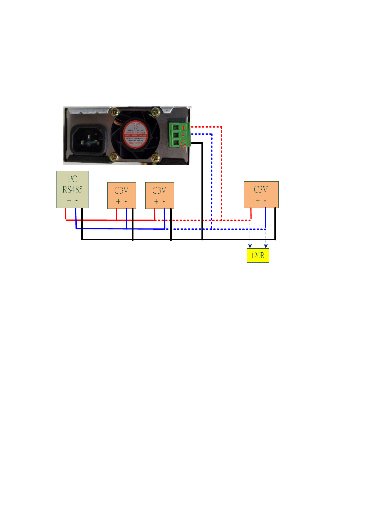
5.4 C³V Series with RS485 Interface
The RS485 address needs to be set up before communication. Each C³V Series must
have a unique address ranging from 1 to 32. The address “0” is reserved for RS-232
and USB interface. Up to 32 units can be connected in parallel.
P.16
5.4.1 RS485 Termination Resistor (120R) Installation & Wiring
When installing, please connect a 120Ω termination resistor to the “+/-“ terminals of
the green terminal block of the final parallel unit of C³V Series.
5.4.2 RS485 Address
The RS485 address must be set from 1 to 32 and cannot duplicated. USB & RS232
interface do not require set up as default value “0” is already factory preset.
Refer to Chapter 4 for instructions on the RS485 address setup and query.
P.17
6. C³V Series Communication Protocol
Commands can be written in either ASCII or hexadecimal codes. C³V Series never
sends messages till it receives the CMD from the PC.
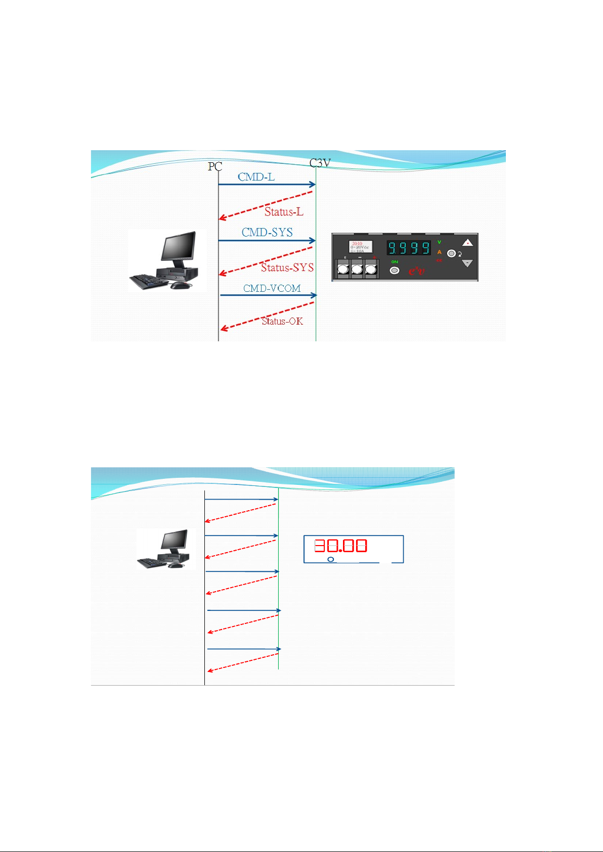
6.1 Communication between PC and C³V Series
As shown below:
PC sends “CMD-L” – C³V Series replies “Status-L”
PC sends “CMD-VCOM” – C³V Series replies “Status-OK”
V
A
CC
On/Off
CMD-L
Status-L
CMD-SYS
Status-SYS
CMD-VCOM
Status-OK
CMD-ICOM
Status-OK
CMD-ON
Status-OK
PC C3V

P.18
6.2 Message Terminator of Protocol: CR LF
CR = 0x0D (HEX)
LF = 0x0A(HEX)
6.3 Data format (PC to C³V)
6.3.1 ADDR (PC to C³V Series)
This field is the address code of the protocol.
If this code is correct, C³V Series will receive commands. Every C³V Series unit can
be set with an address from 1 to 32. When using the RS485 interface, you must set a
unique address code for each power supply.
ADDR Description Interface
C³V00
This is a universal code.
C³V Series will execute commands after
receiving the code.
RS232, USB and RS485
(single unit)

P.19
C³V01
C³V02
.
C³V32
When the C³V Series receives and
decodes the code (address), it will
execute the received command.
. ………..
………..
RS485 (multiple units)
Command Set (PC to C³V Series)
This field is the command code of the protocol.
CMD Function Description
L
The L query returns all C³V Series statuses:
Reply: Status-L
C³V00 L <CR><LF>
Vcom=20.00,Vout=1.35 Icom=3.500,Iout=0.000,Tspace=30.8,Relay=ON
<CR><LF>
SYS
The SYS query returns the model and firmware version of the C³V Series:
Reply: Status-SYS
C³V00 SYS <CR><LF>
C³[email protected]<CR><LF>
VCOM
VCOM sets output voltage level:
Reply: Status-OK
C³V00 VCOM 20<CR><LF>
OK<CR><LF>
ICOM
ICOM sets the output current limit:
C³V00 ICOM 3.5<CR><LF>
OK<CR><LF>

P.20
ON
ON turns the output on:
Reply: Status-OK
C³V00 ON<CR><LF>
OK<CR><LF>
OFF
OFF turns the output off:
Replay: Status-OK
C³V00 OFF<CR><LF>
OK<CR><LF>
Data Format CMD-L (C³V Series to PC)
Status-L (C³V Series to PC)
This field is the command code of this protocol.
Status Function Description
Vcom
Reply voltage value of setting:
C³V00 L<CR><LF>
Vcom=20.00,Vout=1.35,Icom=3.500,Iout=0.000,Tspace=30.8,Relay=ON
<CR><LF>
Other manuals for C3V Series
1
This manual suits for next models
3
Table of contents
Other Trueful Electronics Power Supply manuals

Popular Power Supply manuals by other brands


Elenco Electronics
Elenco Electronics XP-100 instruction manual

Kikusui
Kikusui PWR400L Operation manual

Santerno
Santerno PENTA MARINE user manual

CyberPower
CyberPower PowerPanel Business Edition user manual

Rockwell Automation
Rockwell Automation 1606-XLE480 instruction manual

EVGA
EVGA BQ 80 PLUS BRONZE Series user manual


