Trueheat RCP4 User manual
Trueheat RCP IO Manual—August 2018 Page 1 of 18
Gas Pasta Cooker
INSTALLATION & OPERATION MANUAL
RCP4

Trueheat RCP IO Manual—August 2018 Page 2 of 18
CONGRATULATIONS!
Thank you for choosing Trueheat.
This product has been specifically designed by Comcater to meet a wide range of applications
and represents the best quality and highest value equipment.
Please read the Instruction Manual carefully to ensure the safe and reliable operation and
performance of your equipment.
Should you require service, you will be supported by Comcater’s trained and qualified service
network.
COMCATER AUSTRALIA
www.comcater.com.au
National Head Office
156 Swann Drive, Derrimut, VIC 3030
Phone: 03 8369 4600
Fax: 03 8369 4699
Email: sales@comcater.com.au
Technical Services Group
Phone: 1800 810 161
Fax: 03 8369 4696
Email:
Equipment Servicing (24/7)
service@comcater.com.au
Equipment Spare Parts
spares@comcater.com.au
Technical Support
techsupport@comcater.com.au
Comcater QR Codes
Comcater Website Log a Service Call Online Spare Parts Store
Reproduction or copying of any part of this manual by any means whatsoever is strictly forbidden unless authorised in writing by Comcater. Comcater reserves the
right to change design and specifications without prior notice. © Copyright Comcater Pty Ltd, August 2017.

Trueheat RCP IO Manual—August 2018 Page 3 of 18
TABLE OF CONTENTS
INTRODUCTION
Warranty...........................................................................................................................4
Date Plate Location ..........................................................................................................4
WARNINGS................................................................................................................................ 5
GENERAL INFORMATION .........................................................................................................6
SPECIFICATIONS
Dimensions, Weight & Installation Drawings.................................................................... 7
Accessories & Optional Accessories ............................................................................... 7
Gas Configuration ........................................................................................................... 8
INSTALLATION
Gas Connection .............................................................................................................. 11
Installation Clearances ................................................................................................... 11
Levelling .......................................................................................................................... 11
CONVERSION INSTRUCTIONS ................................................................................................12
COMMISSIONING / BURNER ADJUSTMENT
Leak Test ....................................................................................................................... 12
Test Point Pressure ........................................................................................................ 12
Pilot Adjustment ............................................................................................................. 12
Target Adjustment .......................................................................................................... 12
OPERATION
First Time Use ................................................................................................................13
Daily Operation ...............................................................................................................13
MAINTENANCE
Daily Cleaning ................................................................................................................14
Recommended Service Plan .......................................................................................... 15
TROUBLESHOOTING
Burner will not light .........................................................................................................16
Pilot not lighting ..............................................................................................................16
Trueheat RCP IO Manual—August 2018 Page 4 of 18
INTRODUCTION
GENERAL
The Trueheat RC Series is designed for commercial catering purposes only and incorporates a
wide range of design features. It is designed to deliver high-end performance to fulfill the busy
demands within a commercial kitchen. It is available in various appliances and configurations
including:
Ranges with open burners, griddles with oven or as Counter-Top unit.
Broilers, salamanders, pasta cookers and deep fryers.
This versatility will satisfy a wide range of customer needs.
WARRANTY
12 months replacement of parts including labour, for goods found to be faulty due to defective
materials, manufacture and/or workmanship. This warranty is void if installation, operation and/or
maintenance of the equipment are not in accordance with manufacturer’s instructions and
recommendations.
Unauthorised modifications to the equipment will void the warranty and product certification.
All warranty work will be undertaken in normal working hours from Monday – Friday 8:00am to
4:00pm
Warranty does not extend to:
Damages caused in shipment
Damage as a result of incorrect installation
Damage as a result of incorrect operation
Damages caused by Unauthorised service and use of non-original parts
Gas supply issues to the equipment
Calibration of thermostats after 90 days
Failure resulting from improper maintenance
Failure as a result of tampering with, removal of, or changing any pre-set control or
safety device
After hours Service - Penalty rates apply for afterhours service.
Conditions as defined in Comcater terms and condition of sale, a copy of Comcater’s terms and
conditions of sale can be found at www.comcater.com.au/terms
For all warranty work, authorized service, genuine and authorized spare parts, please contact
Comcater Service 1800 810 161.
Please ensure you quote the Model and Serial Number of the unit.
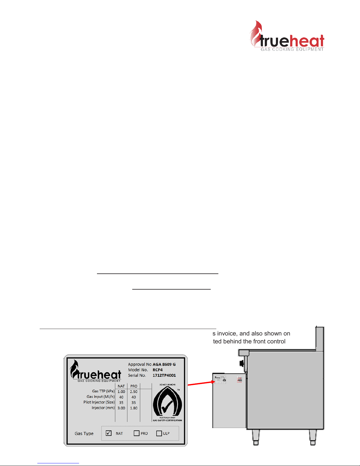
The Model and Serial Number of the unit is recorded on the sales invoice, and also shown on
the top right side of the front control panel. The data plate is located behind the front control
panel.

Trueheat RCP IO Manual—August 2018 Page 5 of 18
IMPROPER INSTALLATION, ADJUSTMENT, ALTERATION, SERVICE
OR MAINTENANCE CAN CAUSE INJURY OR DEATH. THE
INSTRUCTION MANUAL MUST BE READ CAREFULLY BEFORE
INSTALLING, OPERATING OR SERVICING THIS EQUIPMENT.
TO BE INSTALLED ONLY BY AN AUTHORISED PERSON IN
ACCORDANCE WITH AS/NZS 5601.1, LOCAL AUTHORITY, GAS,
ELECTRICITY, ANY APPLICABLE STATUTORY REGULATIONS AND
MANUFACTURER REQUIREMENTS.
THIS EQUIPMENT IS DESIGNED FOR COMMERCIAL CATERING
PURPOSES AND WILL GENERATE SIGNIFICANT HEAT. HOT
SURFACES WILL CAUSE BURNS. A HAZARD AND RISK
ASSESSMENT MUST BE UNDERTAKEN BY OWNERS AND ALL
OPERATORS MADE AWARE OF THESE.
DO NOT STORE OR USE FLAMMABLE LIQUIDS NEAR THIS
APPLIANCE.
DO NOT SPRAY AEROSOLS NEAR THIS APPLIANCE WHILE IT IS IN
OPERATION.
INSTALLATION CLEARANCES AS SPECIFIED MUST BE OBSERVED.
IF YOU SMELL GAS, TURN THE UNIT OFF AND THE MAIN GAS
SUPPLY VALVE TO THE UNIT. CONTACT YOUR GAS SUPPLIER OR
AN AUTHORISED PERSON.
BEFORE TURNING ON THE MAIN GAS SUPPLY, CHECK THE UNIT TO
BE CERTAIN THAT ALL THE VALVES ARE IN THE “OFF” POSITION.
WARNINGS

Trueheat RCP IO Manual—August 2018 Page 6 of 18
GENERAL INFORMATION
INSPECTION
Please inspect the unit on receipt. If the unit is damaged, contact the carrier immediately and le a
damage claim with them. Save all packing materials when ling a claim. Freight damage claims are the
responsibility of the purchaser and are not covered under warranty.
OPERATOR MANUAL
This manual contains important informaon for your safety and the installaon, operaon,
maintenance and service of this equipment. Please read the manual carefully and ensure all
operators of the equipment are aware of the contents and safety requirements. You must also
assess all hazards and risks associated with the operaon of the equipment in your environment and
advise all operators of these.
INSTALLATION
This equipment must be installed by an authorized person in accordance with AS/NZS 5601.1, local
authority, gas, electricity, any applicable statutory regulaons and manufacturer requirements.
GAS CONNECTION
The appliance must be connected by an authorized person to the gas type specied on the unit. The
gas type is shown adjacent to the rear gas connecon point and on the data plate. Connect to and
use only the correct type of gas.
GAS PRESSURE
The authorized person installing this equipment must ensure that the gas operang pressure is the same as
shown on the rang plate and that there is sucient gas volume for the appliance to operator correctly.
COMMISSIONING
The authorized person installing this equipment must commission the equipment in accordance with AS/NZS
5601.1 - gas leakage, operaonal checking, adjustments and instrucng the owner on use of the equipment
are prescribed requirements.
Trueheat RCP IO Manual—August 2018 Page 7 of 18
SPECIFICATIONS
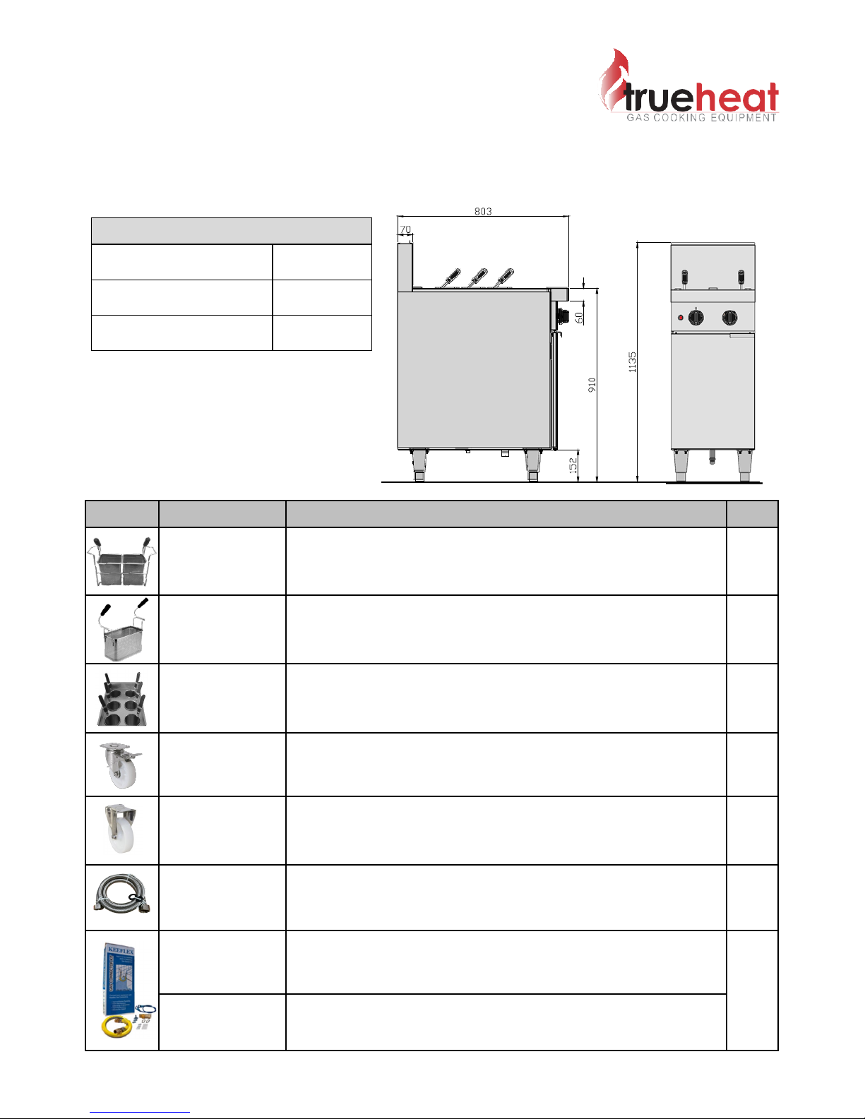
DIMENSIONS, & INSTALLATION DRAWINGS, OPTIONAL ACESSORIES
The following tables and drawings provide all dimension, weight and optional accessories.
IMAGE PART NO. DESCRIPTION *QTY
S45069 Additional Basket Set with Wireframe 1
B21273 Medium Basket 280L X 145W X 180H 1
S35041 Noodle Basket Set with Stainless Steel Frame 1
8100357 Front Castors Swivel with brake 2
8100378 Rear Castors Fixed without brake 2
COM-WF0116 1500mm SS braided water hose 3/4” female & 1/2” female 1
432018-900HK 900mm 3/4” flexible gas hose with quick connect fittings & restraint
1
432018-1200HK 1200mm 3/4” flexible gas hose with quick connect fittings & restraint
DIMENSIONS
Width (mm) 400
Depth (mm) 803
Height (mm) 1135
OPTIONAL ACCESSORIES
*QTY = Quanty required per unit.

Trueheat RCP IO Manual—August 2018 Page 8 of 18
SPECIFICATIONS (cont’d)
GAS CONFIGURATION
NOTES:
1. When checking gas pressure, ensure that all other equipment on the same line is
turned “ON”.
2. Values shown are those measured at the manifold pressure test point.
TO BE COMPLETED BY AN AUTHORISED PERSON.
ONLY CONNECT THE APPLIANCE TO THE GAS TYPE IT HAS
BEEN CONFIGURED FOR. THE GAS TYPE IS SPECIFIED ON
THE DATA PLATE AND AT THE REAR OF THE APPLIANCE.
NATURAL GAS PROPANE GAS
Minimum Gas Inlet Pressure 1.13 kPa 2.75 kPa
Test Point Pressure 1.00 kPa 2.50 kPa
Descripon NATURAL GAS PROPANE GAS
Minimum Inlet Pressure 1.13 kPa 2.75 kPa
Test Point Pressure 1.00 kPa 2.50 kPa
Gas Consumpon 40 MJ/h 40MJ/h
Main Injector 3.00 mm 1.8 mm
Pilot Orice (marking) Adjustable Orifice (35) Adjustable Orifice (35)
Pilot Adjustment 3/4 turn out from fully in Fully in
Low Flame Adjustment 3 turns out from fully in 3 turns out from fully in
Trueheat RCP IO Manual—August 2018 Page 9 of 18
INSTALLATION
Note: Installation is the responsibility of the owner.
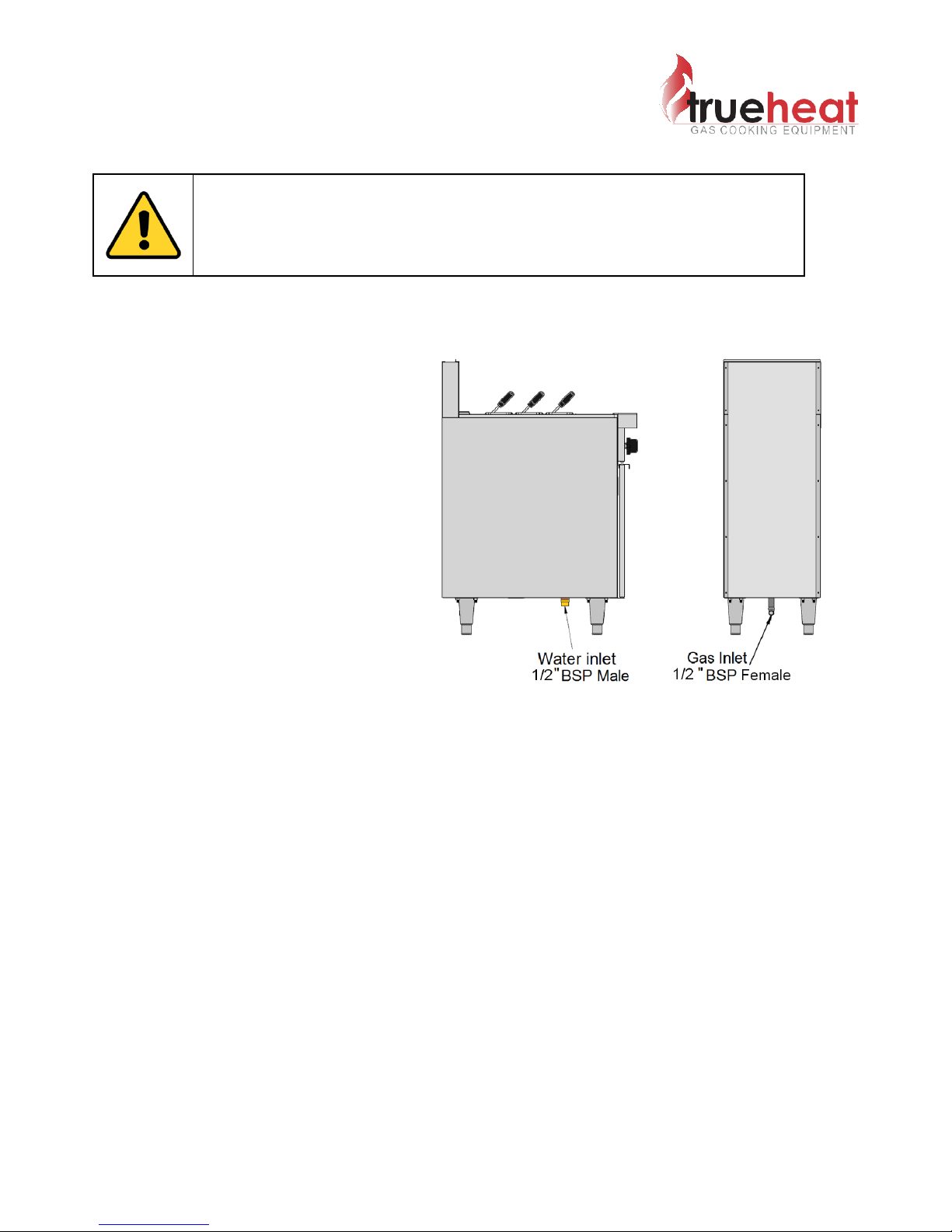
WATER INLET CONNECTION
1/2” BSP Male
GAS INLET CONNECTION
1/2” BSP Female.
GAS CONNECTION POINT
The gas connection point is located lower
at the rear of the appliance.
GAS CONNECTION
The appliance must be connected by an authorised person to the gas type specified on
the unit. The gas type is shown adjacent to the rear gas connection point and on the data
plate. Only connect to and use the specified gas type that the appliance has been set for.
Do not remove or modify any of the gas piping within the appliance. The gas connection
must be made at the connection point provided.
Removal or modification of the gas piping within the appliance will void the gas
certification & manufacturer’s warranty. This may also affect the customer’s insurance
policy.
The authorised person installing this equipment must comply with AS/NZS 5601.1
requirements. Prescribed requirements include, commission the equipment, gas
leakage testing, operational checking and adjustments.
All units are tested and adjusted at the factory; however, burners and pilots must be checked at the
installed location and adjusted if necessary.
THIS EQUIPMENT MUST BE INSTALLED BY AN AUTHORIZED
PERSON IN ACCORDANCE WITH AS/NZS 5601.1, LOCAL
AUTHORITY, GAS, ELECTRICITY, ANY APPLICABLE STATUTORY
REGULATIONS AND MANUFACTURER REQUIREMENTS.
Trueheat RCP IO Manual—August 2018 Page 10 of 18
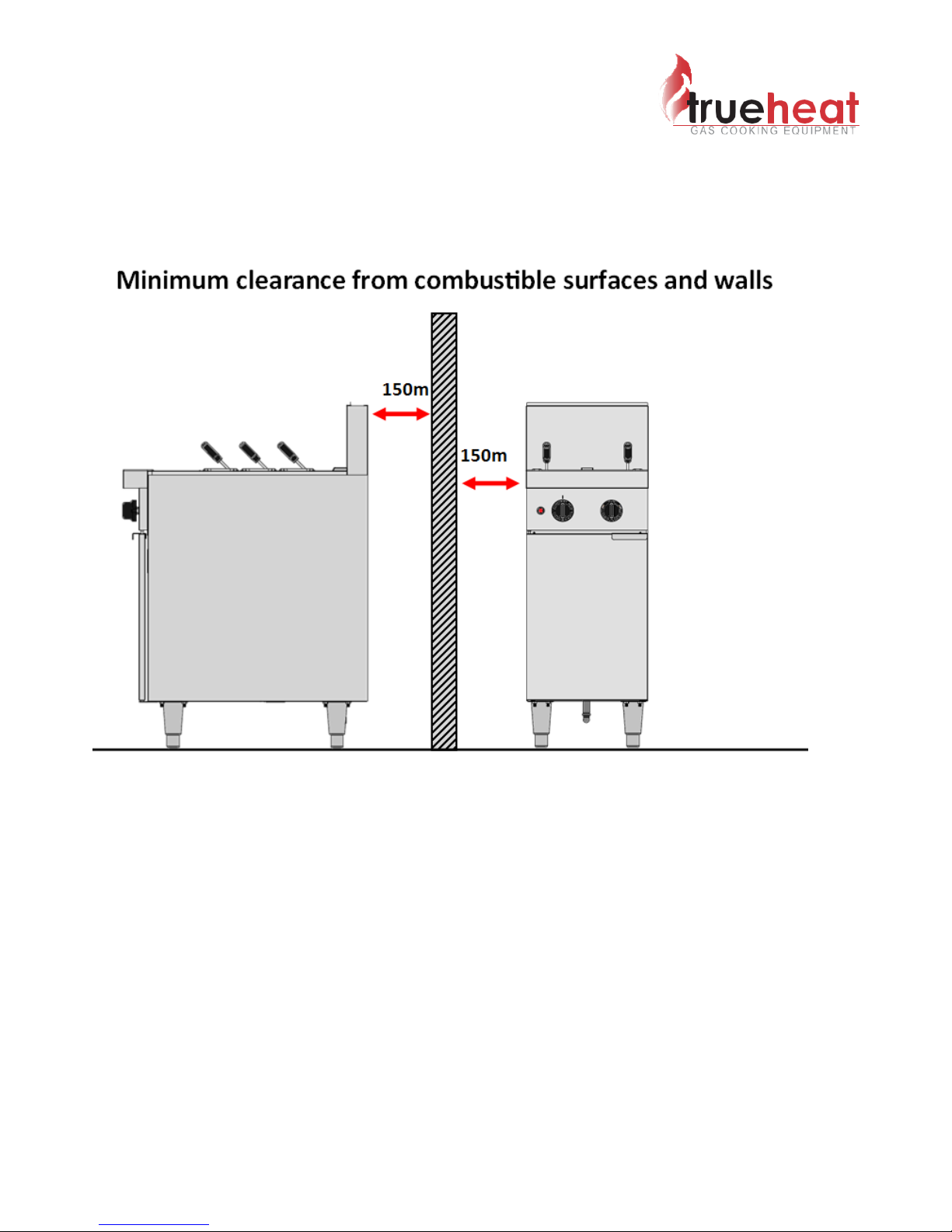
INSTALLATION CLEARANCES
The MINIMUM clearance from combustible surfaces is 150 mm rear
and 150mm on either side. Where castors are used on installations where
combustions are adjacent, ensure that a stand off isolated behind the appliance to
ensure that the customer can reposition the closer than 150mm.
See diagram below.
NOTE:
1. Ensure adequate clearance is provided for service & maintenance.
2. Ensure that the gas regulator is accessible for adjustment
LEVELLING
To adjust the legs to level the unit to the floor and/or to slightly adjust the height of the unit,
raise the front of the unit and adjust the legs (ensure safe work practices). Similarly, raise the
back and adjust the legs.
Castors are non-adjustable and should only be used when are floors level.
DO NOT LAY THE UNIT ON ITS BACK. ENSURE THE UNIT IS LEVELLED.

Trueheat RCP IO Manual—August 2018 Page 11 of 18
COMMISSIONING
LEAK TEST
Ensure that the valve is in the OFF position.
Turn on the main gas supply valve.
Light all pilots.
Leak test the valve and fittings using approved methods.
Correct any leaks as required and re-check.
Shut off the gas valve
TEST POINT PRESSURE
The test point is located on the gas manifold behind the control panel. The test point pressure is
shown on the appliance data plate and in the Gas Configuration Table.
LOW FLAME ADJUSTMENT
The low flame adjustment screw is located on each gas valve adjacent to the control shaft.
Low flame adjustment setting is shown in the Gas Configuration Table on Page 8.
GAS CONTROLS—BEHIND CONTROL PANEL
PRIMARY AIR SETTING
The Primary Aeration shutter setting is gas type specific. When converting between gas types
ensure that the correct Primary Aeration setting and interrupter screw are used per the
diagram below.
WARNING: IF YOU ARE NOT COMPETENT IN PERFORMING ANY
SERVICE TASK OR REQUIRE ASSISTANCE, PLEASE CONTACT:
COMCATER SERVICE
Gas Type Drawing
Reference Aeraon Shuer Seng
Natural Gas A25 mm
Propane Gas BFully Open
Low flame adjustmentLow flame adjustment
Gas control shaftGas control shaft
Pressure test point Pressure test point
Primary aeration shutterPrimary aeration shutter
Pilot AssemblyPilot Assembly
Trueheat RCP IO Manual—August 2018 Page 12 of 18
GAS CONVERSIONS
The RCP4 Pasta Cooker can be configured to operate on either Natural Gas or Propane Gas.
If a Gas Conversion is required, Gas conversation kits are available through Comcater Spare
Parts for either gas type. Detailed conversion Instructions are provided with the Gas
Conversion kits.
NOTE: To arrange a Gas Conversion contact Comcater Service 1800 810 161
ONLY TO BE COMPLETED BY AN AUTHORISED PERSON
ENSURE GAS IS ISOLATED WHILST PERFORMING CONVERSION WORK.
PERFORM A LEAK TEST BEFORE IGNITING AND CALIBRATING BURNER AND
PILOT ADJUSTEMENTS.
RCP4 GAS CONVERSION KIT PART NUMBERS
MODEL NATURAL GAS PROPANE GAS
RCP4 THSP-RCP4-GCKIT-NG THSP-RCP4-GCKIT-LP
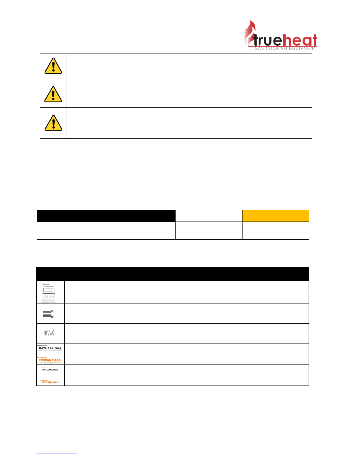
CONTENTS
IMAGE DESCRIPTION
RCP GAS CONVERSION INSTRUCTIONS
BURNER INJECTOR
SPRING FOR GAS REGULATOR
or GAS TYPE LABEL FOR REAR OF APPLIANCE
or GAS TYPE LABEL FOR DATA PLATE

Trueheat RCP IO Manual—August 2018 Page 13 of 18
OPERATION
FIRST TIME USE
Before lighting the equipment for the first time, ensure that all package materials including the stainless
steel protective film have been removed before lighting.
Use warm soapy water and a cloth to wipe down and remove any dust or metal filings that may have
settled during manufacturing.
CORRECT ASSEMBLY
Before first time use, carefully inspect the unit to ensure that nothing has moved or has been damaged
during transport. If there are any concerns please contact Comcater Technical Support 1800 810 161.
FILLING THE TANK
Before filling, ensure that the drain is in the closed position and only operate the pasta cooker when the
water level is at or above the minimum water level indicator on the rear of the tank (see diagram below).
Never leave the pilot light on when the tank is not filled with water. To fill the tank turn the right knob
counter clockwise. Once filled turn the knob clockwise to stop the flow of water.
LIGHTING INSTRUCTIONS
1. Turn the Control knob from position “off” to “Pilot” .
2. Depress control knob and hold it down and light pilot immediately with “piezo ignitor”.
Note: The pilot can been seen through the “pilot viewing hole”.
3. Once the pilot has lit, continue to hold in the control knob for 10 seconds, before slowly releasing.
(Verify that the pilot is still lit once the control knob has been released, if not repeat step 3 & 4).
4. Turn gas control knob to the “Hi-flame” position, the burner will then ignite.
5. If the pilot becomes extinguished, repeat the above procedure.
SHUTDOWN INSTRUCTIONS
1. Turn the gas control knob to the “"off" position.
2. Allow the equipment to cool down before cleaning.
DIAGRAM - OPERATOR CONTROLS
Filling the tank with water.
Water “OFF” Turning
the knob Clockwise
Water “FILL” by turning the
knob Counter Clockwise
“Low-flame”
Control knob marker
“Off” Position
“Pilot”
“Hi-flame” Position
Piezo ignitor
Pilot viewing hole
Minimum water level indicator
Filling spout

Trueheat RCP IO Manual—August 2018 Page 14 of 18
OPERATION / MAINTENANCE
DAILY OPEATION
Once the tank has been filled above the minimum water level, the pilot has been lit and the
burner is switched on, the water in the tank will begin to heat.
It will take between 30 minutes to 1 hour for the water to achieve a rolling boil, depending on the
incoming water temperature.
The pasta cooker has the ability to skim starch from the tank when the tank is full and the filling
tap is opened to a trickle.
This will flush excess starch from the surface of the water, down the skim drain located on the
apron at the front of the tank.
NOTE: Using the trickle feature may hinder the rolling boil.
If a rolling boil is required for a particular cooking process, it is recommended that this feature
isn’t used during cooking. Instead, use the trickle feature to flush excess starch in intervals
between cooking.
Always ensure that the water within the tank does reduce below the minimum water level marker
and never dry fire the tank, and never leave the pilot lit with the tank empty.
DAILY CLEANING
CLEANING STAINLESS STEEL
Regularly wipe the surface with hot water and detergent. Rinse and wipe the washed area with a
wet sponge and clean water and wipe the area dry to prevent streaking. Follow this process and
wash a small area at a time to prevent chemical residue and streaking.
Stainless steel may discolour if overheated. These stains can usually be removed using an
appropriate powder or paste. Use only wood or plastic tools as necessary.
NOTES:
1. Never use steel wool to clean stainless steel.
2. Damage may occur if chemicals not suitable for stainless steel are used.
MAINTAINING A CLEAN TANK
During the cooking process pasta releases starch into the water, most of starch is flushed down
the skim drain or the main drain when the tank is flushed, however deposits do accumulate on
the walls of the tank. Its important to maintain the cleanliness of tank to ensure satisfactory food
safety and optimum thermal efficiency of the pasta cooker.
Neglecting the cleanliness of the tank will reduce the thermal efficiency which will impact on the
pasta cookers overall performance.
Long term affects of poor cleaning can result in damage or failure of the tank.
CLEANING THE TANK
Clean the tank daily with mild detergent and hot water.
Only a non-abrasive brush or cloth. Never use steel wool or abrasive scrubbing pads.
USE ONLY SUITABLE CHEMICALS AND OBSERVE ALL
MANUFACTURER SAFETY REQUIREMENTS
FOR SAFE HANDLING AND USE.

Trueheat RCP IO Manual—August 2018 Page 15 of 18
MAINTENANCE
RECOMMENDED SERVICE PLAN
It is recommended that your appliance be serviced by an authorised person every 12 months. This
period is for guidance purpose only and may vary based on usage of the equipment and operator care.
Prescribed service tasks include:
Functional test of all components, clean and adjusted as necessary
Inspect and clean all gas valves and lubricate with an industry approved lubricant
Inspect all gas piping
Check and adjust specified gas pressures
Leak test
Full operation, performance and safety test
For all technical queries, please contact Comcater’s Technical Support Team.
Technical Phone Support
Phone: 1800 810 161
Email: techsuppor[email protected].au
FOR YOUR SAFETY, ALL SERVICE WORK MUST BE CARRIED OUT BY
AN AUTHORISED PERSON AND USE ONLY ORIGINAL SUPPLIED AND
SPECIFIED PARTS.
TEST ALL FITTINGS, PIPES AND PIPE CONNECTIONS FOR LEAKS IN
ACCORDANCE WITH APPROVED GAS LEAK TEST PROCESSES AND
METHODS. DO NOT USE A FLAME.

Trueheat RCP IO Manual—August 2018 Page 16 of 18
TROUBLESHOOTING
For all technical queries regarding troubleshooting please contact Comcater Technical Support:
Phone: 1800 810 161 Email: [email protected]
Problem Probable Causes Corrective Action
Burner will not light
Pilot is not lit
Light the pilot as per
instructions shown on the
inside of the door or on Page
14 of this manual
Gas Control is set to “Pilot”
Once a pilot has been
established, ensure that the
gas control dial is set to
“Hi-Flame” .
No gas supplied to unit
Verify that the gas line is
connected, ensure all manual
or automatic shutoff valves are
open, including emergency gas
shut-offs. Note: some exhaust
systems have a gas supply
interlock fitted, that will
disrupted gas supply to the
equipment if the exhaust hood
isn’t operating.
Pilot will not light
Pilot injector has a blockage
or
Gas pressure is too low
When the pilot is lit, the flame
is too small to activate the
thermocouple and hold the
pilot on.
The repair is beyond the scope
of the operator, please call
Comcater service to organise a
technician.
Pilot lights, but will not stay lit
When the pilot is lit, the flame
is good, but the pilot won’t stay
lit, or drops out during service.
The repair is beyond the scope
of the operator, please call
Comcater service to organise a
technician.

Trueheat RCP IO Manual—August 2018 Page 17 of 18
NOTES

Trueheat RCP IO Manual—August 2018 Page 18 of 18
www.comcater.com.au/trueheat
Table of contents
Popular Pasta Maker manuals by other brands

Villaware
Villaware V5400 Recipe and instruction booklet

Falcon
Falcon DOMINATOR PLUS E3204 Installation and servicing instructions

Silvercrest
Silvercrest SPM 220 A1 operating instructions

Gastroback
Gastroback 90763 operating instructions

MAXXMEE
MAXXMEE PN310 manual

Westmark
Westmark 6130 2260 quick start guide


