Truma iNet Box User manual

Operating Instructions Page 2
To be kept in the vehicle!
iNet Box

2
iNet Box
Table of Contents
Symbols used ........................................................................ 2
Intended use ....................................................................... 2
Operating Instructions
Safety instructions ............................................................. 3
Display and control panels / connections ...................... 3
Preparing start-up .............................................................. 4
Install the Truma app on mobile terminal device .................. 4
Device identification .............................................................. 4
Bluetooth communication ................................................ 4
Bluetooth connection set-up ................................................. 4
Bluetooth bonding ................................................................. 5
GSM communication ......................................................... 5
Preparing iNet Box ................................................................ 5
Setting up the GSM connection ............................................ 5
Operation ............................................................................ 6
Technical data ..................................................................... 6
Troubleshooting guide ...................................................... 6
Factory setting .................................................................... 6
Cleaning ............................................................................... 6
Maintenance ...................................................................... 7
Disposal ............................................................................... 7
Accessories ......................................................................... 7
Declaration of conformity ................................................. 7
Warranty declaration ......................................................... 8
Symbols used
Note containing information and tips.
Intended use
The iNet Box was developed for controlling TIN-bus-capable
Truma devices via mobile terminal devices (e.g. smartphones,
tablet PCs). Communication is via Bluetooth or GSM.

3
Operating Instructions
Safety instructions
– iNet Box must not be operated unless it is in technically per-
fect condition.
– Repairs must be carried out immediately. Only carry out
repairs yourself if the solution is described in the trouble-
shooting guide of this manual.
– A defective iNet Box may only be repaired by the manufac-
turer or the manufacturer’s service department.
– Do not perform any modifications to the iNet Box as this
can be dangerous.
– Changes or modifications not expressly approved by the
party responsible for compliance could void the user’s
authority to operate the equipment.
– This device complies with Part 15 of the FCC Rules and with
Industry Canada license-exempt RSS standard(s). Operation
is subject to the following two conditions:
(1) this device may not cause harmful interference, and
(2) this device must accept any interference received,
including interference that may cause undesired
operation.
– Le présent appareil est conforme aux CNR d‘Industrie
Canada applicables aux appareils radio exempts de licence.
L‘exploitation est autorisée aux deux conditions suivantes :
(1) l‘appareil ne doit pas produire de brouillage, et
(2) l‘utilisateur de l‘appareil doit accepter tout brouillage
radioélectrique subi, même si le brouillage est suscepti-
ble d‘en compromettre le fonctionnement.
Display and control panels / connections
Display panels
BLUETOOTH
POWER
GSM
iNet Box
Figure 1 – Top view
LED Description
Blue Bluetooth – flashes for Bluetooth pairing with 1Hz
Green Power – lights up when ready for operation
Red GMS – lights up when GSM operation is not possible
Control panels / connections
SIM
GSM
EXT
INT
1
2 43
Figure 2 – Rear view
Item Description
1 Bluetooth / factory setting button
2 Insert, Mini-SIM card (25 x 15 mm)
3 External antenna connection GSM (SMA)
4 Changeover switch, internal / external antenna

4
Preparing start-up
Install the Truma app on mobile terminal device
1. Load the Truma app (at www.truma.com) onto the mobile
terminal device.
2.Install the Truma app on the mobile terminal device.
If necessary, an installed Truma app must be updated.
3.Repeat steps 1 and 2 for additional mobile terminal devices.
4.To continue installation, start the “Set-up assistant” of the
Truma app or follow the instructions below.
Device identification
The TIN-bus-capable Truma devices connected to the iNet Box
and CP plus must be known to the CP plus.
1.Connect all TIN-bus-capable Truma devices to the CP plus
and the iNet Box.
2.Switch on the power supply for the devices connected to
the CPplus and iNet Box (including iNet Box).
3.Perform the device search on the CP plus (see CP plus oper-
ating instructions, “Initial start-up”).
After a repair / retrofitting, the device search with
CPplus must be repeated.
4.At least the Bluetooth communication must be set up for
each mobile terminal device.
5.Switch on all devices connected to the iNet Box (see
“Bluetooth connection set-up” on Page 4).
Bluetooth communication
Bluetooth connection set-up
To connect the mobile terminal device to the iNet Box, the
mobile terminal device must be switched on and Bluetooth
must be activated (see the operating instructions of the mo-
bile terminal device).
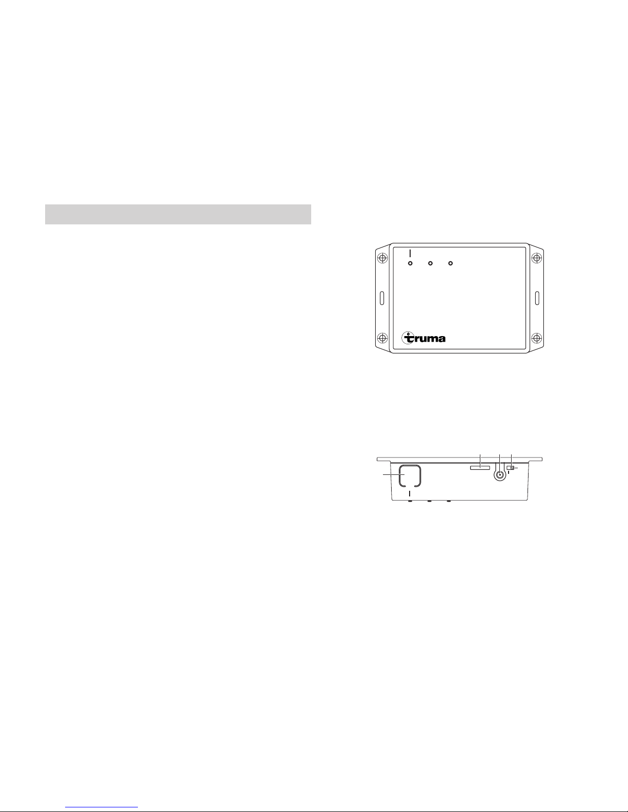
– Press the button (Figure 2 – 1) for approximately 1 second.
If the Bluetooth pairing is active, the iNet Box becomes
visible for 3minutes and the blue LED (Figure 1) flashes at
the same time at a frequency of 1 Hz. The name “iNet Box”
appears on the mobile terminal device.
The Bluetooth connection to the mobile terminal device can
be made.
Up to 20 mobile terminal devices can be logged on /
saved on the Bluetooth connection. Four mobile terminal
devices can control the iNet Box at the same time.
The first mobile terminal device set up (administrator) remains
permanently in the iNet Box memory. The 21st mobile ter-
minal device overwrites the second one in the memory. This
means that each new mobile terminal device logged on over-
writes the oldest one in the memory.
The first mobile terminal device set up (administrator)
can only be deleted by restoring to the factory setting
(see “Factory setting” on page 6on Page 6) in the iNet
Box.

5
Bluetooth bonding
If there is a saved mobile terminal device within range of the
iNet Box, a Bluetooth bonding to the iNet Box is automatically
performed.
GSM communication
Preparing iNet Box
A Bluetooth connection must first be established before
the GSM communication can be set up and operated.
A Mini-SIM card with its own call number and sufficient credit
is required for GSM communication. The Mini-SIM card is not
included in the scope of delivery.
Insert the Mini-SIM card
Position the Mini-SIM card (25 x 15 mm) so that the missing
corner faces the slot and the contact surface faces the bottom
of the iNet Box.
Push the Mini-SIM card into the “SIM” slot until it engages.
SIM
GSM
EXT
INT
Mini-SIM
Figure 3
Removing the Mini-SIM card
Pressing the Mini-SIM card again enables it to be removed.
Setting up the GSM connection
An active Bluetooth connection is required for the continued
installation and the Truma app on the mobile terminal device
must be started.
1. Select the “set-up assistant” of the Truma app
2.Via the “set-up assistant”, enter the PIN and the call num-
ber of the Mini-SIM (iNet Box), and also a freely selectable
name (maximum 11 characters).
Notes:
– The Mini-SIM card is blocked after 3 incorrect PIN entries.
To unblock, the Mini-SIM card must be removed from the
iNet Box and unblocked in the mobile terminal device with
the PUK.
– If the Mini-SIM card is replaced, the GSM connection must
be set up again before using the GSM communication.

6
Operation
To operate the devices connected via the iNet Box, follow the
steps in the Truma app.
– The last incoming command is executed.
– Bluetooth communication has priority over GSM
communication.
– The iNet Box automatically switches from GSM to Bluetooth
communication as soon as a saved mobile terminal device
comes into reception range.
– It automatically switches back to GSM communication
when the device goes out of reception range.
Technical data
Dimensions (L x W x H) 147 x 96 x 40 mm
Operating conditions
Temperature -30°C to +60°C
Humidity 10%rH to 99%rH
Air pressure 942 hPa to 1061 hPa
Storage temperature range -30°C to +70°C
Interface TIN bus
Power supply 9V – 29V
Power consumption xxx mA
Standby current xxx mA
Weight approx. 500g
External GSM antenna
Anntenna gain max. 5.5 dBi at 850 MHz and max. 2 dBi at
1900 MHz
Subject to technical changes.
Troubleshooting guide
The green “Power” LED (ready for operation) does not light up.
Check the operating voltage.
LED red – GSM error
– No GSM reception
– No Mini-SIM card
– Mini-SIM card blocked
– Modem error
Progress bar stops during firmware update
/ Bluetooth connection interrupted for an extended time / pre-
vious firmware status remains.
Factory setting
Reset all settings to the factory setting and delete all individual
data.
– Press the button (Figure 2 – 1) for at least 20 seconds.
The blue LED flashes briefly to indicate that resetting has
been done.
Cleaning
Clean only with a moist, lint-free cloth. Make sure that no liq-
uid gets inside the iNet Box. This can cause a short circuit and
destruction of the iNet Box.

7
Maintenance
There are no components inside the iNet Box that re-
quire servicing by the customer.
If it is faulty, replace the complete iNet Box.
Firmware update
An iNet Box firmware update is indicated in the Truma app on
the mobile terminal device. Transmission is via Bluetooth (fol-
low the instructions in the Truma app).
Disposal
The device must be disposed of in accordance with the ad-
ministrative regulations of the respective country in which it is
used. National regulations and laws (in Germany, for example,
the End-of-life Vehicle Regulation) must be observed.
Accessories
External GSM antenna
TIN-bus cable, 3 different lengths
Declaration of conformity
1. Information about the manufacturer
Name: Truma Gerätetechnik GmbH & Co. KG
Address: Wernher-von-Braun-Str. 12, D-85640 Putzbrunn
2. Device identification
Type / model:
GSM control unit / iNet Box
3. Complies with the requirements of the following
ECdirectives
3.1 Electromagnetic compatibility 2004/108/EC
3.2 Radio interference suppression of motor vehicles UN ECE R10
3.3 End-of-life vehicle directive 2000/53/EC
3.4 Low Voltage Directive 2006/95/EC
and bears the CE mark and the type approval number E1
xxxxxxxxxxxxx
4. Basis of the proof of conformity
6. Signatory details
Signature: xxxxx
xxxxxxxx Putzbrunn, 17.11.2014

8
Warranty declaration

9

Las instrucciones de uso y de montaje en su idioma pueden
solicitarse al fabricante Truma o al Servicio postventa Truma
en su país.
Saat käyttö- ja asennusohjeen pyynnöstä omalla kielelläsi
valmistajalta (Truma) tai maasi Truma-huoltoon.
Spør om bruks- og monteringsanvisning på norsk hos
produsenten Truma eller Trumas serviceavdeling i landet ditt.
Μπορείτε να ζητήσετε τις οδηγίες χρήσης και τοποθέτησης
στη γλώσσα της χώρας σας από τον κατασκευαστή Truma ή
από το σέρβις της Truma στη χώρα σας.
Návod k použití a montážní návod si lze v řeči Vaší země
vyžádat u výrobce Truma nebo servisu Truma ve Vaší zemi.
Návod na použitie a montáž vo Vašom štátnom jazyku si
môžete vyžiadať u výrobcu Truma alebo v servise Truma vo
Vašej krajine.
As instruções de utilização e montagem podem ser
solicitadas junto do fabricante Truma ou do serviço de
assistência da Truma no seu país.
Az Ön nyelvén a használati és beszerelési utasítás a Truma
gyártójától vagy az adott ország Truma szerviztől szerezhető be.
Instrukcję obsługi i instrukcję montażu w Państwa wersji
językowej można otrzymać w firmie Truma lub serwisie firmy
Truma znajdującym się w Państwa kraju.
TR Dilinizdeki kullanma ve montaj talimatı, üretici Truma'dan
veya ülkenizdeki Truma servisinden talep edilebilir.
Руководство по эксплуатации и монтажу на Вашем
национальном языке можно запросить у изготовителя Truma
или в сервисной службе фирмы Truma в Вашей стране.

Installation Instructions Page 2
iNet Box

2
iNet Box
Table of Contents
Symbols used ........................................................................ 2
Installation Instructions
Safety instructions ............................................................. 3
Intended use .......................................................................... 3
Scope of delivery ................................................................... 3
Accessories ........................................................................... 3
Dimensions ............................................................................ 3
Connections .......................................................................... 3
Displays ................................................................................. 4
Selecting a location ............................................................... 4
Connection examples ............................................................ 5
Assembly ............................................................................... 7
Symbols used
The unit must only be installed and repaired by an
expert.
Note containing information and tips.

3
Installation Instructions
Safety instructions
In-vehicle installations must comply with
the technical and administrative regula-
tions of the respective country of use (e.g.
EN 1648, VDE 0100-721). National regula-
tions and rules must be followed.
In other countries, the relevant regulations
must be observed.
Intended use
The iNet Box was developed for controlling TIN-bus-capable
Truma devices via mobile terminal devices (e.g. smartphones,
tablet PCs). Communication is via Bluetooth or GSM.
Scope of delivery
1 iNet Box
1 Fastening bracket
1 Set of operating instructions
1 Set of installation instructions
1 12 V connector cable 30 cm (+ = red ,
-
= blue)
1 Connector cable (TIN-bus)
Accessories
External GSM antenna
TIN-bus cable, 3 different lengths
Dimensions
L x W x H 147 x 96 x 40
The dimensions are in mm
Connections
Front view
POWER (9 V – 29 V operating voltage)
TIN 1
TIN 2

4
Rear view
1BLUETOOTH / factory settings button
2Mini-SIM (25 x 15 mm)
3External antenna connection GSM (SMA)
4Changeover switch, internal / external antenna GSM
Displays
Top view
Blue LED (BLUETOOTH pairing status)
Green LED (POWER lights up during operation)
Red LED (GSM) lights up when GSM operation is not possible.
Selecting a location
Install the iNet Box in a location that is protected from mois-
ture and humidity. For optimum transmission and reception,
secure the iNet Box as high up as possible, e.g. above a win-
dow and in the middle of the vehicle. At the same time, due
to the position of the installed antennae, the connections
should go upwards or downwards (secure the box perpendic-
ular on the wall).
The slot for the Mini-SIM and the external GSM antenna
connection, the internal / external antenna changeover
switch and the button for the BLUETOOTH pairing must
remain accessible.
Connect the external GSM antenna
People must maintain a distance of at least 20 cm from the
antenna.

5
Connection examples
– Plug the cable (TIN-bus) into the iNet Box TIN 1/2 and con-
nect it to a TIN-capable heater and/or air conditioning sys-
tem (from 01.04.2015 onwards, the heater can only be
operated in conjunction with a CPplus control panel).
– Plug in the 12 V connector cable and attach to unswitched
12V operating voltage (permanent positive). Protect the
positive cable with a 1 A fuse (near to the positive terminal
of the power source).
When the CPplus control panel is used, the same circuit as
that of the iNet Box must be used.
Figure 1
Figure 2
Figure 3

6
Figure 4
Figure 5
Figure 6
Figure 7

7
Assembly
Initial start-up should be carried out before starting assembly
– Download the app to the mobile phone
Establish the Bluetooth connection to the iNet Box
Search for the location with the best Bluetooth reception
– Establish the position of the iNet Box (safety clearance >20cm
from people).
– Fix the iNet Box to the wall at the established position using
the two adhesive strips (the surface must be clean and
smooth).
– Lay the iNet Box cables clear of the 230 V cables (approx.
20cm) .
– The cables must have strain relief.
Subject to technical changes.

Truma Gerätetechnik GmbH & Co. KG
Wernher-von-Braun-Straße 12
85640 Putzbrunn
Deutschland
Service
Telefon +49 (0)89-4617-2020
Telefax +49 (0)89 4617-2159
www.truma.com
50000-15100 · 01 · 12/2014 ·
Bei Störungen wenden Sie sich bitte an das Truma
Servicezentrum oder an einen unserer autorisierten
Servicepartner (siehe www.truma.com).
Für eine rasche Bearbeitung halten Sie bitte Gerätetyp und
Seriennummer (siehe Typenschild) bereit.
Should problems occur, please contact the Truma Service
Centre or one of our authorised service partners
(see www.truma.com).
In order to avoid delays, please have the unit model and serial
number ready (see type plate).
Veuillez vous adresser au centre de SAV Truma ou à un de
nos partenaires de SAV agréés en cas de dysfonctionnements
(voir www.truma.com).
Pour un traitement rapide de votre demande, veuillez tenir
prêts le type d’appareil et le numéro de série (voir plaque
signalétique).
In caso di guasti rivolgersi al centro di assistenza Truma
o a un nostro partner di assistenza autorizzato
(consultare il sito www.truma.com).
Affinché la richiesta possa essere elaborata rapidamente,
tenere a portata di mano il modello dell’apparecchio e il
numero di matricola (vedere targa dati).
©

Truma Gerätetechnik GmbH & Co. KG
Wernher-von-Braun-Straße 12
85640 Putzbrunn
Deutschland
Service
Telefon +49 (0)89-4617-2020
Telefax +49 (0)89 4617-2159
www.truma.com
50050-15200 · 01 · 12/2014 ·
Bei Störungen wenden Sie sich bitte an das Truma
Servicezentrum oder an einen unserer autorisierten
Servicepartner (siehe www.truma.com).
Für eine rasche Bearbeitung halten Sie bitte Gerätetyp und
Seriennummer (siehe Typenschild) bereit.
Should problems occur, please contact the Truma Service
Centre or one of our authorised service partners
(see www.truma.com).
In order to avoid delays, please have the unit model and serial
number ready (see type plate).
Veuillez vous adresser au centre de SAV Truma ou à un de
nos partenaires de SAV agréés en cas de dysfonctionnements
(voir www.truma.com).
Pour un traitement rapide de votre demande, veuillez tenir
prêts le type d’appareil et le numéro de série (voir plaque
signalétique).
In caso di guasti rivolgersi al centro di assistenza Truma
o a un nostro partner di assistenza autorizzato
(consultare il sito www.truma.com).
Affinché la richiesta possa essere elaborata rapidamente,
tenere a portata di mano il modello dell’apparecchio e il
numero di matricola (vedere targa dati).
©
Other manuals for iNet Box
8
Table of contents