Trumpf TruTool TPC 165 User manual


Table of contents
1 Safety 4
1.1 General safety information 4
1.2 Specific safety information for Panel Cutter
TPC 165
5
2 Description 7
2.1 Intended use 7
2.2 Technical data 9
2.3 Icons 9
2.4 Noise and vibration information 10
3 Setting work 12
3.1 Changing/tensioning the tool 13
4 Operation 15
4.1 Working with the Panel Cutter 15
Checking the tool 16
Working procedure 16
Overload protective device on the motor 18
4.2 Main machine position 18
4.3 Table markings 19
4.4 Plunging depth 20
4.5 Guide rails 20
Working with the guide rail 20
4.6 Cutting along scribed line 21
4.7 Slide rails and wearing plate 22
Replacing the slide rails 23
Replacing the wearing plate 23
Replacing the front wearing plate 23
4.8 Exhaust system 23
4.9 Electronic signal display 24
5 Maintenance and repairs 26
5.1 Maintenance 26
Set screw - Adjusting the ratchet 27
5.2 Repairs 28
Replacing carbon brushes 28
2Table of contents E848EN_00


1. Safety
1.1 General safety information
■Read all safety warnings and all instructions including those
in the brochure also supplied.
■Failure to follow the warnings and instructions may result in
electric shock, fire and/or serious injury.
■Save all warnings and instructions for future reference.
Electrical voltage! Risk of fatal injury due to electric shock!
ØRemove the plug from the plug socket before undertaking
any maintenance work on the machine.
ØCheck the plug, cable and machine for damage each time
before using the machine.
ØKeep the machine dry and do not operate it in damp rooms.
ØConnect the fault current (FI) circuit breaker with a maxi-
mum breaking current of 30 mA when using the electric tool
outside.
ØOnly use original TRUMPF accessories.
ØIf the connection cable has to be replaced, this may only be
done by the manufacturer or an authorized dealer to avoid
safety hazards.
Damage to the machine due to improper handling.
ØWear safety glasses, hearing protection, breathing protec-
tion, protective gloves and working shoes when working.
ØConnect the plug only when the machine is switched off.
Pull the power plug after use.
ØDo not carry the machine by the cable.
ØHave maintenance carried out by specialists.
Note
If the power cable is to be replaced, it should be procured from
the manufacturer or an authorized dealer to avoid safety haz-
ards.
4Safety E848EN_00
DANGER
WARNING

1.2 Specific safety information for Panel
Cutter TPC 165
Electrical voltage! Risk of fatal injury due to electric shock!
ØHold the machine with both hands on the insulated handle
during machining.
ØAlways keep the power cable behind the device and do not
pull it over sharp edges.
ØDo not perform any work that may cause the machine to
come into contact with hidden power lines or its own cable.
Contact with a live conductor can cause metallic machine
parts to become live and can lead to an electric shock.
Risk of injury to hands.
ØDo not reach into the processing line with your hands.
ØDo not reach into the saw chain with your hands.
ØDo not reach under the workpiece. The saw chain and the
blade are unguarded when they are in the swivelled out sta-
tus.
ØNever hold the workpiece in your hands or over your leg
during machining.
Health risks especially damage to muscles and joints due
to strong vibrations during operation.
ØCarry out machining at normal feed power.
E848EN_00 Specific safety information for Panel Cutter TPC 165 5
DANGER
WARNING
WARNING

Risk of injury due to improper handling!
ØMake sure the machine is always in a stable position when
operating it in order to absorb any possible kickback forces.
ØAlways operate the machine away from your body.
ØDo not carry out overhead work on the machine.
ØThe machine may only be operated with a protective cover.
ØIf the saw falls down, check that the saw chain and saw
blade move freely afterwards. The protective cover and
other parts must not be touched.
ØBefore putting the machine down, ensure that the blade is
folded in.
ØIf the saw should get stuck in the material, release the
switch and do not move the saw in the material until the
saw chain stops. When restarting, center the saw blade in
the kerf and make sure that the teeth of the saw chain are
no longer stuck.
ØBlades of the predecessor models (e. g. TP 150-0 and
TPC 150-2) as well as damaged blades must not be used.
ØFollow the instructions for lubrication, chain tensioning and
changing accessories. An improperly tensioned or lubricated
chain can break.
ØKeep the handles clean and free of oil and grease. Greasy,
oily handles are slippery and will lead to loss of control.
Risk of injury through defective brake!
ØCheck the brake before every use. The brake must stop
movement of the chain within 2 s. If there is a defect, inform
TRUMPF Service.
ØDo not clamp the switch for the saw chain and swivel lever
for the blade.
ØIf the saw falls down, check the brake for perfect operation
afterwards.
6Specific safety information for Panel Cutter TPC 165 E848EN_00
WARNING
WARNING
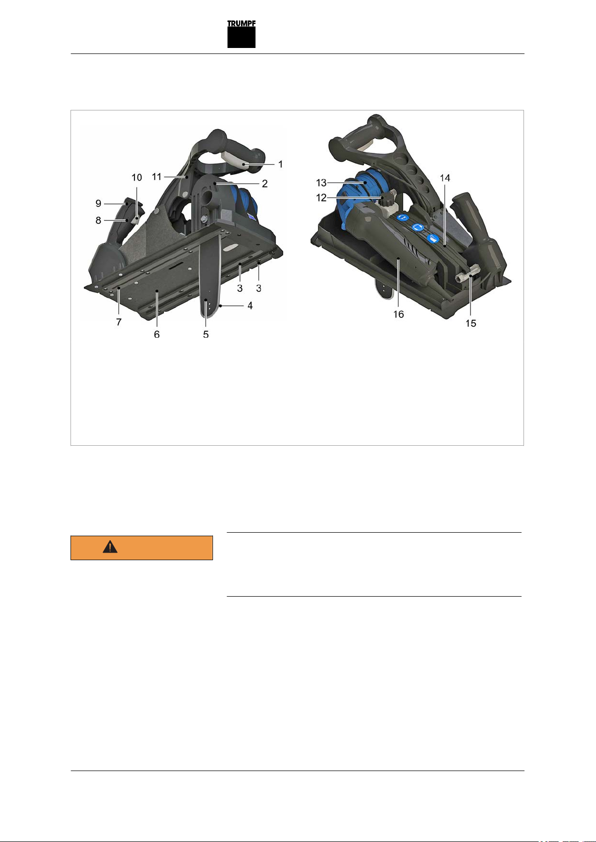
2. Description
1 Swivel lever, blade
2Protective cover and suction
connection piece, vacuum
cleaner
3 Slide rails
4 Saw chain
5 Blade
6 Support table
7 Wearing plate
8Switch, saw chain
9 Adjustable grip
10 Release button
11 Lever handle, blade
12 Oil tank cover
13 Gearbox
14 Cover
15 Combination wrench
16 Motor
TruTool TPC 165 Fig. 67302
2.1 Intended use
Danger of injury and health hazard!
ØOnly use the machine for the work and materials described
under "Intended use".
ØDo not cut materials containing asbestos.
The TRUMPF Panel Cutter TPC 165 is an electrically operated
hand-held device:
■For commercial use in industry and trade.
■For efficiently cutting panels with metal outer shells and poly-
urethane or polyisocyanurate rigid foam insulation (roof and
wall panels).
■For easy piercing in panels for producing cornered cutouts.
E848EN_00 Description 7
WARNING

■For cutting along a scribed line.
■For cutting with a guide rail.
8Intended use E848EN_00

2.2 Technical data
Other countries USA
Values
Voltage 230 V 120 V 110 V 120 V
Frequency 50/60 Hz 50/60 Hz 50/60 Hz 50/60 Hz
Working speed 4 m/min 4 m/min 4 m/min 9.8 ft/min
Nominal power consumption 1400 W 1400 W 1400 W 1400 W
Idle stroke rate n02300/min 2300/min 2300/min 2300/min
Cutting track width 4 mm 4 mm 4 mm 4 mm
Weight 9.6 kg 9.6 kg 9.6 kg 21.2 lbs
Safety class
II / II / II / II /
Technical data Tab. 1
Other countries USA
Permissible material thicknesses
Individual material thickness for
steel up to 400 N/mm2
0.9 mm 0.9 mm
(0.035 in)
With insulation made of polyur-
ethane foam (PUR) and polyisocya-
nurate foam (PIR)
165 mm 165 mm (6.4 in)
Permissible material thicknesses Tab. 2
Other countries USA
Minimum cutouts
Blade 165 340 x 340 mm 340 x 340 mm
(13.5 x 13.5 in)
Minimum cutouts Tab. 3
2.3 Icons
Note
The following symbols are important for reading and understand-
ing the operator's manual. The correct interpretation of the sym-
bols will help you operate the machine better and safer.
Icon Name Meaning
Read operator's manual Read the operator's manual and safety information in
their entirety before starting up the machine. Closely
follow the instructions given.
Wear safety glasses. Chips could fly out of the tool.
E848EN_00 Technical data 9
Icon Name Meaning
Wear gloves. Chips could fly out of the tool.
Wear hearing protection. Noise emission value can be exceeded.
Danger of injury due to rotating
saw.
Do not reach into the saw chain with your hands.
Safety class II Indicates a doubly insulated tool.
Alternating current Type or property of current
V Volt Voltage
A Ampere Current, current input
Hz Hertz Frequency (oscillations per second)
W Watt Power, power input
mm Millimeters Dimensions e.g.: material thickness, chamfer length
in Inch Dimensions e.g.: material thickness, chamfer length
noIdle speed Revolution speed without load
.../min Revolutions/strokes per minute Revolution speed, stroke rate per minute
Tab. 4
2.4 Noise and vibration information
Noise emission value may be exceeded.
ØWear hearing protection.
The vibration emission value can be exceeded!
ØSelect the right tools and exchange them in time in the
event of wear.
ØHave maintenance carried out by trained specialized techni-
cians.
ØDefine additional safety measures for protecting the operator
from the effect of vibrations (e. g. keep hands warm, organi-
zation of working procedures, machining at normal feed
force).
ØDepending on the operating conditions and state of the elec-
tric tool, the actual load might be higher or lower than the
specified measured value.
Health risks especially damage to muscles and joints due
to strong vibrations during operation.
ØCarry out machining at normal feed power.
10 Noise and vibration information E848EN_00
WARNING
WARNING
WARNING

Notes
■The specified vibration emission value was measured in
accordance with a standardized testing procedure and can
be used to compare one electric tool with another.
■The specified vibration emission value can also be applied
for a provisional estimate of the vibration load.
■Times during which either the machine is switched off or run-
ning but not actually in use can considerably reduce the
vibration load during the entire working period.
Designation of measured value Unit Value according to
EN 60745
Vibration emission value ah (vector
sum of three directions)
m/s25.1
Uncertainty K for vibration emission
value
m/s21.5
A-class acoustic pressure level LPA
typically
dB (A) 89
A-class acoustic power level LWA
typically
dB (A) 100
Uncertainty K for noise emission
value
dB 3
Tab. 5
E848EN_00 Noise and vibration information 11

3. Setting work
Risk of fatal injury due to electric shock!
ØRemove the plug from the plug socket before changing the
tool or undertaking any maintenance work on the machine.
Damage to property!
Wear and destruction of the saw chain and blade, tool
failure.
ØDo not tension the saw chain too tautly (see "Fig. 67306",
pg. 14).
ØWhen inserting the saw chain, always pay attention to the
tooth direction.
ØDo not operate the saw chain without lubricant (see "Tab.
8", pg. 26).
ØAvoid collisions during work. Do not cut into nails, screws,
etc.
Damage to property due to the wrong tools being used!
Reduction in service life of the tools.
ØDepending on the application, use the right tools according
to the following table.
Panel thickness (outer plate + foam insula-
tion)
Saw chain 165 with
blade 165
max. 165 mm
Tab. 6
Both the saw chains as well as the blades are meant for pro-
cessing panels with outer plates up to a tensile strength of
400 N/mm² and a thickness up to 0.9 mm. A panel thickness up
to 165 mm with foam insulation can be processed.
The machine is suitable for cutting panels with the insulation
materials polyurethane foam (PUR) and polyisocyanurate foam
(PIR).
Note
If the structure of the panels to be processed vary from the
above-described version (thicker outer plates or higher tensile
strength, other insulation materials), it is to be expected that the
service life of the saw chain and blade will be reduced. Also,
penetrating into the material with the blade might be more diffi-
cult, or might not be possible at all.
12 Setting work E848EN_00
DANGER
NOTICE
NOTICE
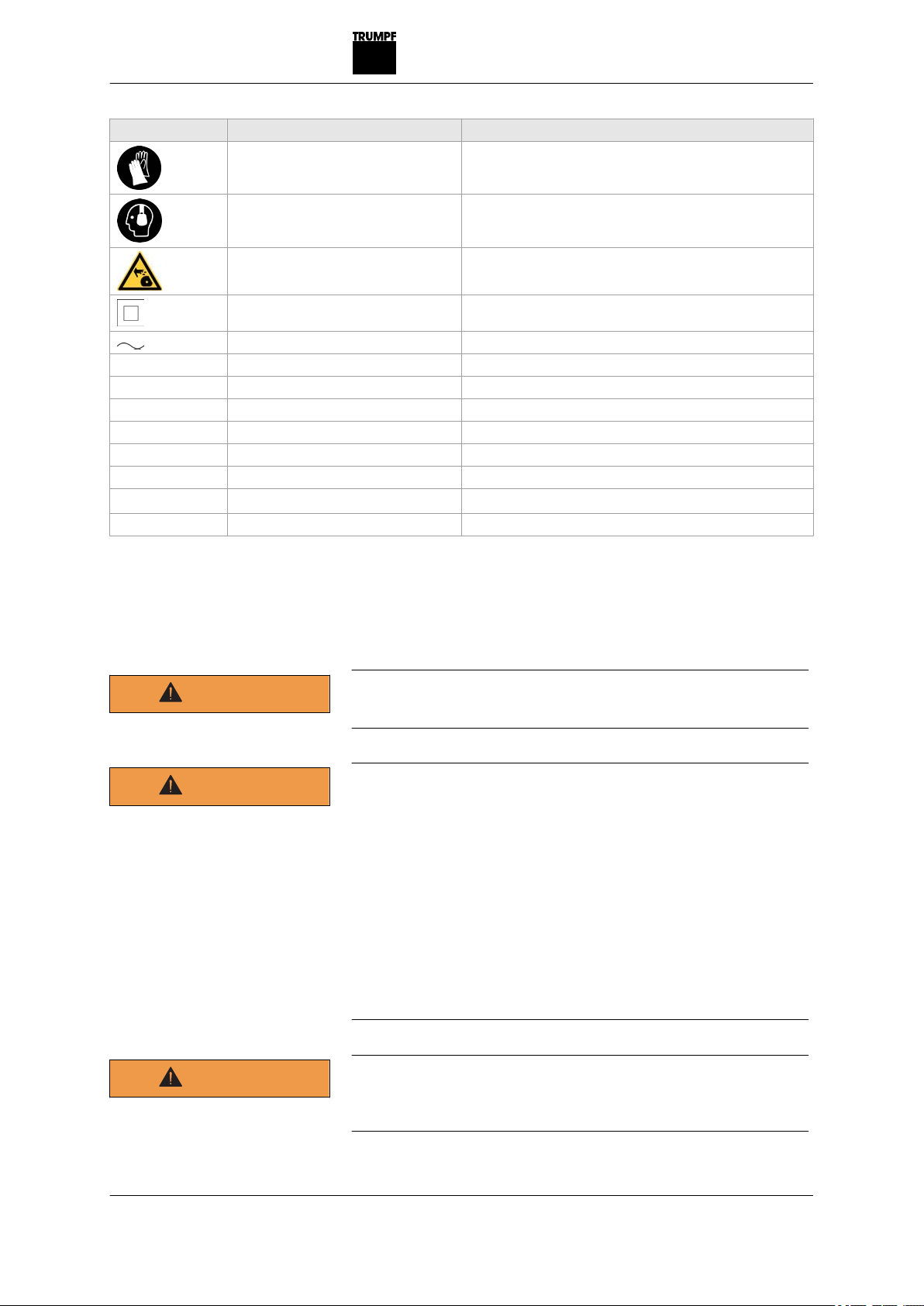
3.1 Changing/tensioning the tool
1 Chain wheel
2Saw chain
3 Blade
4 Chain tightener
5Protective cover
6 Hexagon-head screws
Fig. 67303
1. Loosen the hexagon-head screw (6) using a combination
wrench (in the cover) and remove.
2. Take off the protective cover (5).
3. Shift the blade (3) by turning the chain tensioner (4) toward
the chain wheel (1).
4. Lift the saw chain (2) with the blade (3) out of the chain
wheel (1).
1 Oil channel
Fig. 31844
E848EN_00 Setting work 13
Removing the saw chain
Checking the oil channel

Damage to property.
A clogged oil channel can lead to increased wear or to the
saw chain breaking.
ØClean the oil channel regularly.
5. Check the oil channel. It must not be dirty.
6. Insert a new saw chain in the blade and chain wheel. While
doing so, pay attention to the running direction (arrow) of the
saw chain.
Correct chain tension Fig. 67306
7. Shift the blade by turning the chain tensioner. Tension the
saw chain until it can be lifted approx. 3 mm (dimension, see
Fig. 67306) from the blade by hand (measuring point is mid-
dle of blade).
8. Stick on the protective cover.
9. Screw the protective firmly in place using the hexagon-head
screws (6).
10. Loosen the hexagon-head screw (6) using a combination
wrench (in the cover) with one turn.
11. Shift the blade by turning the chain tensioner.
12. Tension the saw chain until it can be lifted approx. 3 mm
(dimension, see Fig. 67306) from the blade by hand (meas-
uring point is middle of blade).
13. Screw the protective cover firmly in place.
14 Setting work E848EN_00
NOTICE
Inserting the saw chain
Tensioning the saw chain

4. Operation
4.1 Working with the Panel Cutter
Damage to property due to excessively high line voltage!
This could result in motor damage due to overload.
ØCheck the line voltage. The power supply voltage must cor-
respond to the information on the nameplate of the machine.
Risk of injury due to improper handling!
ØMake sure the machine is always in a stable position when
operating it.
ØNever touch the tool while the machine is running.
ØAlways operate the machine away from your body.
ØDo not carry out overhead work on the machine.
ØThe machine may only be operated with the protective
cover.
Work is performed with two-hand operation for all machine posi-
tions.
2-hand control device Fig. 67304
When operating the machine ensure that the machine is held
with both hands in such a way that both hands are kept away
from the processing point.
E848EN_00 Operation 15
CAUTION
WARNING
2-hand control device

Checking the tool
Damage to property caused by blunt tools!
Machine overload.
ØCheck tools every hour for wear. Sharp saw blades have
good cutting performance and prevent damage to the
device. Change the saw chain in due time.
ØCheck whether both tools, the saw chain and the blade, are
correctly mounted.
Working procedure
Damage to property!
Wear and destruction of the saw chain and blade, tool
failure.
ØDo not tension the saw chain too tautly (see "Fig. 67306",
pg. 14).
ØWhen inserting the saw chain, always pay attention to the
tooth direction.
ØDo not operate the saw chain without lubricant (see "Tab.
8", pg. 26).
ØAvoid collisions during work. Do not cut into nails, screws,
etc.
16 Working with the Panel Cutter E848EN_00
NOTICE
NOTICE
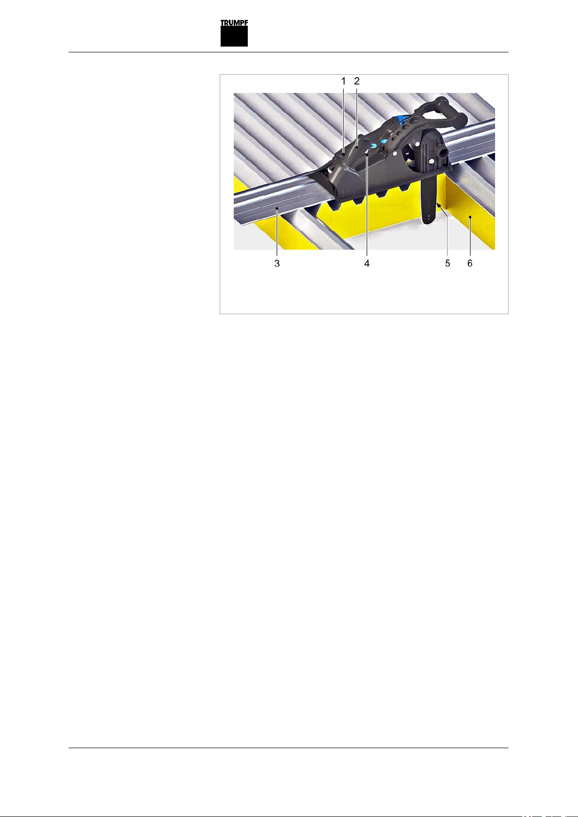
1 Motor
2 Switch
3 Guide rail
4 Release button
5Saw chain
6 Panel
Fig. 67305
1. Fill the oil tank with punching and nibbling oil.
2. Press the release button (4)(see "Fig. 67305", pg. 17) and
then press the switch (2).
Motor (1) switches on, saw chain (5) runs.
3. Keep the switch (2) pressed for approx. 2 minutes until both
oil hoses have filled with oil.
4. Pierce into the material from above.
The machine is equipped with an electronic start-up current
limiter. Therefore, make sure that the machine is only guided
toward the workpiece when it is switched on and has
reached its full speed.
When piercing into the full panel, the panel can kick back
when the running tool comes into contact with it.
Notes
■A new chain will elongate and must be retensioned after
approx. 15 - 20 cut meters.
■If the saw chain jams during cutting, immediately switch
off the motor (see "Fig. 67305", pg. 17) (2), retract the
machine and restart.
5. Cut the material.
When cutting, the chain tension (section 3.2) and the oil level
(oil level indicator below the angular gear) must be checked
regularly.
E848EN_00 Working with the Panel Cutter 17
Putting integrated
lubrication device into
operation when used for
first time
Working with the Panel
Cutter
Checking the chain tension
and oil level

Tip
During cutting, the saw chain is constantly lubricated with the
fully automatic lubricating device. The lubricating oil is usu-
ally sufficient for a cutting length of approx. 150 m.
6. Release the switch (2) (see "Fig. 67305", pg. 17).
The saw chain (5) will stop within 2 seconds and the motor
shuts off.
7. Swing in the blade.
The blade is in its parking position and is thereby protected
from contamination and damage.
8. Have the machine lie level with the table on the panel (6) or
guide rail (3).
Overload protective device on the motor
Notes
■The appliance may switch off prematurely when affected by
electromagnetic interference. The appliance will resume oper-
ation when the faults have been cleared.
■If the motor temperature is too high, the motor limits the
input power. The red indicator light (LED) on the motor lights
up.
1. Allow the machine to run in idle until it has cooled down.
2. Operate the machine normally after it has cooled down.
4.2 Main machine position
In the main machine position, the machine lies with the support
table flat on the material and the blade is aligned vertically
downward. Cutting in the main machine position generates a ver-
tical cut.
18 Main machine position E848EN_00
Switching off the Panel
Cutter

Main machine position Fig. 67307
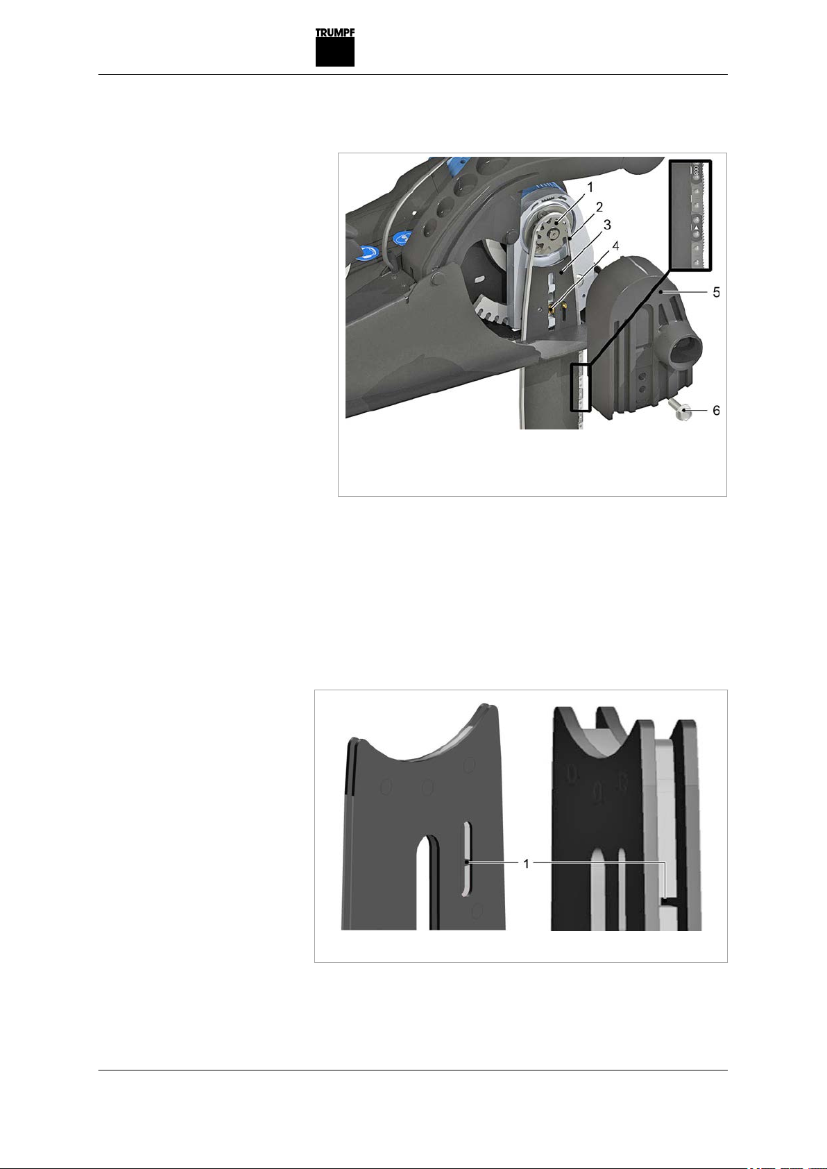
4.3 Table markings
The three markings on the side of the table indicate the front
and rear sides of the blades in the main machine position and
the blade insertion positions. If the chain tension slackens, the
actual cutting edge deviates from the marked position.
1 Blade insertion position in the
support table
2 Rear side of the blade
3 Front side of the blade
4 Cut marking, front
5 Marking for straight cut
Markings on the support table Fig. 67308
E848EN_00 Table markings 19
For a straight cut, make sure that the marking (4) lies at the cut
each time.
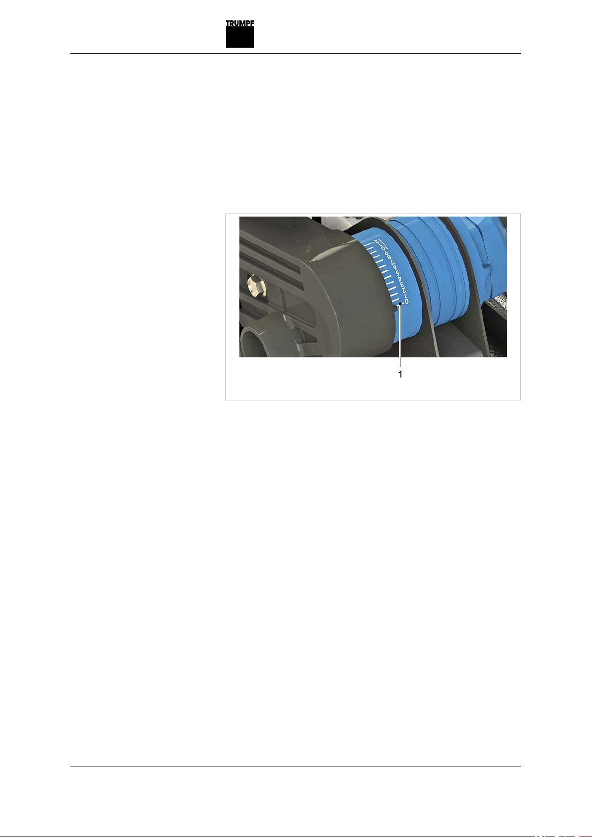
4.4 Plunging depth
The scale on the gear housing indicates the plunging depth of
the blade in stages 0 - 12.
1 Scale on the gear housing
Fig. 67464
4.5 Guide rails
Using the guide rail allows:
■a clean, straight cut.
■better machine guidance.
■easy processing of roof panels (trapezoidal shape).
■protection of the panel surfaces. Scratch-free panel process-
ing is possible.
Working with the guide rail
The guide rail (4), together with the guide notch (3) in the
machine table, guarantees straight machine guidance.
20 Plunging depth E848EN_00
Using the guide rail
(options)
Table of contents
Other Trumpf Cutter manuals


Popular Cutter manuals by other brands


Craftsman
Craftsman CompuCarve 133.217540 Operator's manual

Koike
Koike IK-72T Operation manual

Lincoln Electric
Lincoln Electric OPTITOME2 HPC III instruction manual

Alpha tools
Alpha tools A-FS 1800 UG Original operating instructions

Ironton
Ironton 30091 owner's manual

Weber mt
Weber mt SM 57-2 Operating and maintenance manual

G&J Hall
G&J Hall POWERBOR PB32 instruction manual

Dexter Laundry
Dexter Laundry 956657 Assembly, Use, Maintenance Manual

Borkey
Borkey 919 REXA 5 operating manual

ARCBRO
ARCBRO Spark Series Operator's manual

Ingersoll-Rand
Ingersoll-Rand 326 Operation and maintenance manual

Koike
Koike PICLE1-II Operation manual