Borkey 919 REXA 5 User manual

OPERATING MANUAL
Stand 11/2020
Please read before commissioning!
919 REXA
5

2
Transfer or duplication of this document, as well as exploitation and disclosure of its
contents are prohibited, if not expressly permitted beforehand. Contraventions will
compel you to be liable for damages. All rights for the case of patent application, as
well as utility model and design registration are reserved.
Copyright 2020 by August Börkey Nachf. GmbH, D-58285 Gevelsberg

3
Dear Customer!
With purchasing the Börkey key cutting machine 912 REXA you have chosen a
German quality product. It was manufactured with the highest accuracy and
underwent a precise quality inspection.
This operating manual will help you carry out works with the new machine accurately
and hazard-free. This is why we ask you to thoroughly read the corresponding
information and to carefully observe them.
After unpacking the machine must be checked for transport damage that may have
occurred. Complaints of any kind must be reported immediately. Subsequent
complaints cannot be considered.
It is absolutely necessary to state the machine type and the machine number in all
queries and spare parts orders. (See type label)
Machine disposal
The transport and protective packaging are made from the following materials:
Corrugated cardboard
Polyethylene foil
If you no longer need the parts or want to use them, dispose of them at the public
recycling points.
96% of the machine is made of recyclable materials such as steel, grey cast iron and
4% of chemical materials such as wire insulation of electric lines, circuit boards.
If you have any problems to properly dispose of these parts, then we are happy to
help:
We take the machine back entirely and dispose of it according to prior
agreement.
5

4
Table of contents
General remarks
1. About the operating manual 5
2. Delivery and installation 6
3. Safety provisions 7
4. Safety installations 8
5. Notes for usage the machine 9
6. Description 9
7. Technical data 9
8. Accessories 10
9. Wiring diagram 10
10. Maintenance 11
11. Main function parts 12
12. Spare part list 14
13. Working notes 15
14. Inspection - adjustment 17
15. Description of the 4-way reversible jaw 18
16. Troubleshooting 19
EC Declaration of Conformity 20

5
1.About the operating manual
Please read before commissioning!
Any person operating, servicing or repairing the machine must read and
understand the operating manual before commissioning, particularly the safety
provisions.
Notes on the operating manual
The operating manual shall facilitate getting to know the machine 912 REXA 5and to
use it for the intended application.
The operating manual contains important notes for operating the machine
912 REXA 5safely and properly. Observing it helps avoid hazards and reduces repair
costs and down time.
The operating manual always has to be available at the operating site of the
machine.
Any person working with and on the machine must read and make use of the
operating manual for works including:
•Operating, including setting-up, troubleshooting in the operation,
disposal of production waste, servicing
•Maintenance (upkeep, inspection, overhaul) and / or
•Transport
Next to the operating manual and the mandatory accident prevention regulations in
the country and on the operating site where the machine is used, the generally
recognised rules for safe and proper working must be observed.
Keep this manual in a safe place for future reference !
For any inquiries please contact:
August Börkey Nachfolger GmbH
Geerstr. 4-12
58285 Gevelsberg
Tel.: 0049 2332 7006-0
Fax: 0049 2332 7006-22
Email: info@boerkey.de
www.boerkey.de

6
2. Delivery and installation
The machine is carefully packed in the factory.
Check after delivery:
1. If the packaging is damaged or
2. If the machine shows any transport damage or if it is objectionable.
In this case we ask you to inform us immediately. Subsequent complaints
cannot be considered.
The installation site for the machine must be dry and have a suitable height as well
as a level and firm ground.
The machine must not be operated outdoors, in explosion-prone areas or in
immediate vicinity to flammable substances.
The installation site should be selected in a way so that the electrical supply line with
Schuko socket and 0-conductor is installed close enough to the machine so that
there is no tensile load on the supply line.
Before commissioning, the mains voltage must be compared with the machine power
rating plate.
Connection must only be made via a correctly installed isolated ground receptacle.
The machine must not be operated without the existing safety installations.
Separate the main plug from the mains if the location of the machine changes.

7
3. Safety provisions
1. Works on the machine must only be conducted by professionally instructed
personnel. Observe the legal minimum age!
The warranty expires if damages occur due to improper handling.
2. We point out that we do not assume liability for damages that occur due to
non-compliance with this operating manual.
3. The machine operator must make sure that at least one copy of this operating
manual is kept in immediate vicinity to the machine and that it is accessible to
all persons working on the machine.
4. The operator must make sure that the safety information and the hazard
warnings on the machine are observed and that the signs are in legible
condition.
5. Never work without safety goggles.
6. Wear tight clothes and a hair net if you have long hair. Do not wear loose
clothing (ties, shirt sleeves, jewellery etc.).
7. Ear protection must be worn as of an emission sound pressure level of 80 dB
(A) in the workplace.
8. Never leave the machine running without supervision.
9. Categorically, no safety installations must be modified, disassembled or taken
out of commission. The safety installations prevent damages.
10.Secure the machine in a way so that it cannot be activated by children.
Persons not instructed must not activate the machine.
11.Make sure before using the machine that it is in proper condition. Shut down
the machine if any recognisable damage or defect impairing the safety has
occurred or if any unusual noises can be heard. Pay special attention to any
damages on the main plug or the electric connection. Never use the machine
with a defective, pinched or bare cable.
12.Insert the shock proof plug into a main socket suitable for the machine. The
supply line for the machine must only be connected to a isolated ground
receptacle. The main socket or the terminal box must have been installed by
an electrically qualified person beforehand.
13.The isolated ground receptacle must be close to the machine so that there is
no tensile load on the current-carrying cable.
14.Installation work must only be conducted with deactivated drive.
15.Do not reach into the running machine.
16.Always shut down the machine if you do not use it.

8
17.Repairs must be conducted by a qualified expert! Maintenance work must only
be conducted by persons qualified for the respective maintenance work who
are familiar with the corresponding working safety be conducted by persons
qualified for the respective maintenance work who are familiar with the
corresponding working safety.
17. Repairs must be conductedby a qualified expert! Maintenance work must only
be
18.Protect the machine against moisture.
19.Check the machine for damages regularly. Replace damaged parts with
original parts only and have them exchanged by an expert. The warranty and
guarantee expire if accessories and spare parts are used that are not aligned
to the machine.
20.Do not remove accruing swarfs by hand. Use appropriate tools (hand brush,
brushes).
21.Tools and workpieces must never be changed if the machine is running.
22.Blanks must be fastened in a way so that they are not moved from their
positions by the cutter torques.
4. Safety installations
In order to ensure risk-free working with our machine 912 REXA ,we have provided
the following safety installations and thereby observe the applicable European safety
requirements:
1. Protective cutter cover
The protective cutter cover is attached to the machine casing and is to prevent
reaching into the revolving cutter. For fast tool changes, loosen the cylinder
screws to remove the safety cowl on the cutter.
2. Swarf protection
The swarf protection is to prevent chips from sputtering upwards.
3. ON / OFF switch with low-voltage release
The ON / OFF switch on the back of the machine is equipped with a low-
voltage release, i.e. the machine will not reactivate itself automatically after a
power failure. This way, the risk due to an unexpected motion of the cutter is
avoided.
4. Electrical overload protection
The machine is equipped with an electrical overload protection (fuse) in the
IEC socket. This fuse is automatically destroyed upon any overload. The
machine can only be activated again after the spare fuse has been
exchanged.
5

9
5.Information about the use of the machine
Proper usage
The machine Börkey 912 REXA 5is exclusively designed for cutting cylinder keys,
car keys, and cross keys.
Any other use beyond that is not deemed proper.
The manufacturer is not liable for damages resulting thereof.
The risk is borne solely by the user.
Observance of the operating manual and the maintenance conditions is part of
the proper use.
6.Descrition
Semi-automatic key cutting machine
Börkey 912 REXA
for cutting keys by sample
Main features of the machine
•Copies any cutting angle in the roll off method without changing the cutter
•Quickly adjustable 4-way reversible jaw
•Exchangeable wear parts
•Maintenance-free sintered bushings mounted cutting spindle
•Electronically sensor vernier adjustment of the depth
•The power supply for the milling drive is disrupted or enabled in the basic
position or working condition of the key holder
•Safeguard against reactivation of the machine after an power loss and return
of power
•Energy-saving LED lighting
•Separate connection cable
7. Technical data
Power rating 265 W
Supply voltage 220-240 V
Frequency 50 Hz
Weight 24 kg
Space requirement 57x43x30 cm
Sound pressure level, after 3 GSGV 77 dB (A)
5
10
8. Accessories
Best.- Nr.
1. 4 setting gauges 9954-204-008
2. 2 pins Ø 1.2 9954-204-010
3. 2 stops with recess 9954-204-014
4. 1 brush 9000-021-001
5. 1 allen key SW 2 9000-022-001
6. 1 allen key SW 2.5 9000-022-002
7. 1 allen key SW 3 9000-022-003
8. 1 allen key SW 4 9000-022-004
9. 1 allen key SW 8 9000-022-010
10. 1 spanner SW24 9000-023-003
11. 1 spanner SW 10 9000-023-008
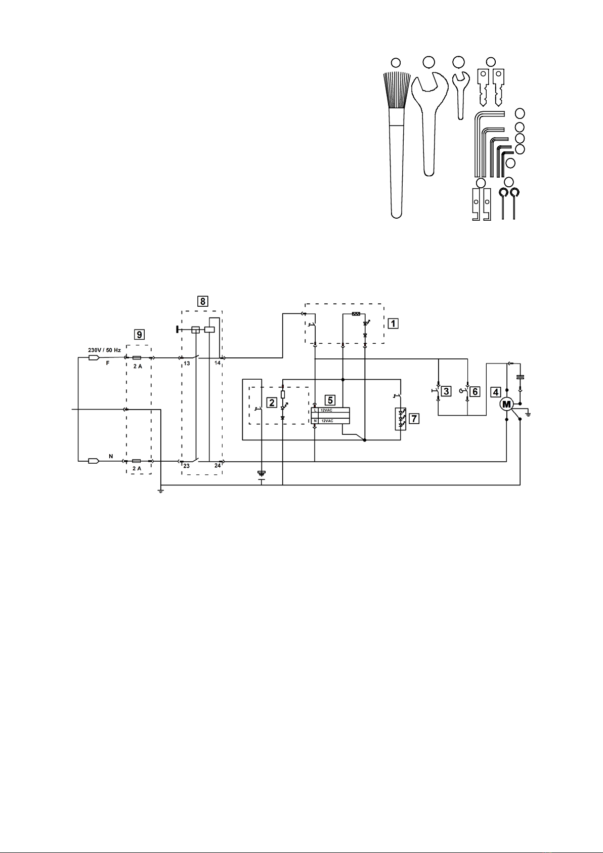
9. Wiring diagram
1= Power on/off switch complete 9 912-013-006
2= Power on/off switch adjustment 9 000-039-123
3= Button wire brush complete 9 912-013-007
4= Motor 9 000-026-091
5= Power supply pack 9 912-013-005
6= End switch 9 000-039-112
7= LED lamp 9 912-013-004
8= Restart switch 9 000-039-122
9= inlet connector 9 000-057-004
3. 2.
5.
7.
8.
9.
10. 11.
4. 1.
6.
11
10. Maintenance
The machine must be cleaned of metal residue (e.g. swarfs) in regular intervals.
(Brush)
You have to check in regular intervals that no metal residue (e.g. swarfs) can accrue
between the cutter and the machine body. (Clean with brush)
-Do not use compressed air!
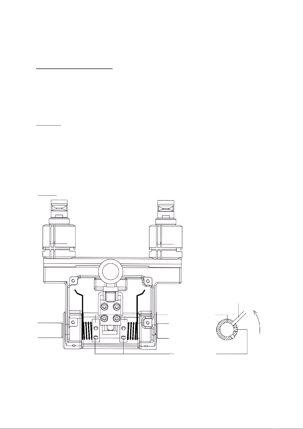
Possible retension (spring pressure too low) of the lateral springs in the key holder
can be achieved by the spring tension mounted beneath the key holder. To do that,
remove the key holder sheet and loosen the setscrew of the spring tightening
coupling. Turn the spring tightening coupling upwards using a pin ∅4 and retighten
the setscrew again (pic.3).
Lubricate the following parts approx. every 4 month (earlier if needed) with a good
machine oil or grease:
- Keyholder shaft
- Feed lever
Do not lubricate the cutting spindle!
Absolutely keep the drive pulley and the
drive belt free of grease !
Picture 3
adjusting sleeve
socket screws
Side view
metal bar Ø 4mm
s
e
n
s
e
o
f
r
o
t
a
t
i
o
n
12
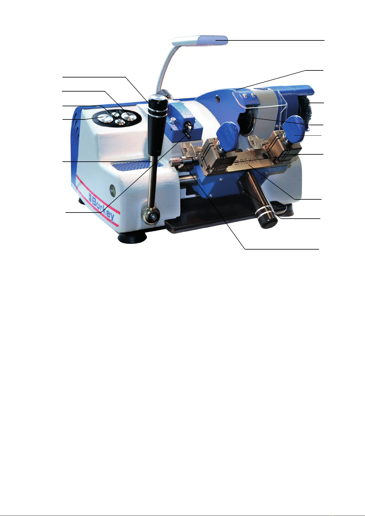
11. Main function parts
Push button machine ON-OFF (1)
Push button blue - machine on
Push button neutral - machine off
Push button machine adjustment of depth ON-OFF (2)
Push button at the bottom - adjustment on
Push button at the top - adjustment off
Push button activation of the wire brush ON-OFF (3)
Push button pressed - machine on
Push button not pressed - machine off
Intake cutter (4)
Shut down the machine when exchanging the cutter. Loosen the cylinder screws to
remove the safety cowl on the cutter (5).
Loosen the tightening nut (4) by using a jaw spanner (SW 24) in clockwise rotation.
Insert allen key (SW 8) into the cutter shaft as a brace to avoid twisting of the cutter
shaft.
Remove tools and insert another cutter in the cutter shaft and push it in all the way.
Tighten the tightening nut by counter-clockwise rotation and install the protective cap
of the cutter.
After a successful exchange of the cutter, check the cutting depth and the lateral
distance
feeler – cutter and if necessary adjust (page 13).
Correct, if necessary, the setting of the spacer (14). (Page 10)
Caution ! Absolutely remove the brace from the
cutter shaft before activating the machine.
4
6
3
1
1
2
8
11
7
9
14
13
10
1
5

13
Intake wire brush (5)
Exchanging the wire brush
Before replacing cutters, loosen the cylinder screws and remove the safety cowl
on the cutter.
Plastic brush (6)
Replacing the plastic brush
Loosen the screw in the plastic brush receiver (4 mm Allen key), draw the plastic
brush to the right out of the receiver, insert a new plastic brush, and tighten the
cylinder screw in the plastic brush receiver.
Schlüsselaufnahme (7)
Spannaufnahmen für Schlüssel und Vorrichtungseinheiten.
Linke Aufnahme für Musterschlüssel, rechte Aufnahme für den zu bearbeitenden
Rohling.
LED lamp (7)
Stop lever (8)
The keys, key blank and samples are lengthwise aligned
with the stop levers.
Preparation and check (page 11 and 12)
Key holder (9)
Springy mounted work piece carrier with safeguard (10) and stop lever (8).
Safeguard key holder (10)
The safeguard always holds the key holder (9) in starting position for
preparatory works. Unlock for working position by pulling it up.
It can only be operated if the stop levers (8) are in basic position.
Wingnuts (11)
Turning the wingnuts secures the sample key and key blank.
Adjustment spindle depth adjustment (12)
The adjustment spindle of the depth adjustment enables the precise setting of the
cutting depth in the key blank. (Page 13)
Spacer (13)
The spacer protects the key intake against damage by the cutter.
A check or re-setting must be conducted after any change of the cutter diameter or
any re-adjustment.
Re-adjustment: - Deactivating the machine –
Key holder in starting position.
Loosen the setscrew in the feeler mounting using an allen key SW 2.5 and unscrew
the spacer (14) several turns. Lead the key holder to the feeler and cutter.
Screw in the spacer (14) until the largest possible cutting depth is achieved.
Lock the setscrew in the feeler mounting.

14
12. Spare part list
8954-000-001 Prism cutterØ80 x 4,4mm
9912-005-000 feeler mounting complete
9912-005-006 feeler insert
9912-013-004 LED lamp
9000-026-091 Drive motor
9912-013-006 Blue pressure switch with ring lighting ON-OFF
9000-039-123 Green pressure switch adjustment ON-OFF
9912-013-007 Pressure switch wire brush ON-OFF
9912-013-005 Power pack
9000-039-122 Restarting switch
9912-014-005 Swarfs protection
9994-014-007 Swarfs trough
9912-012-006 Feed lever complete
9912-009-002 Stop lever
9919-009-003 Collet stop plate left
9919-009-004 Collet stop plate right
9919-009-002 Stop plate
9912-003-000 Bearing unit complete
9919-004-001 Adapter plastic brush
9919-004-002 Plastic brush
9000-151-011 Conical groove belt
9912-010-000 Clamping jaw complete
9000-093-117 Wingnut
9912-007-002 Leg spring right
9912-007-003 Leg spring left
9912-012-006
9912-009-002
8954-000-001
9912-013-004
9919-010-000
9912-005-000
9912-013-007
9994-010-002
9000-039-123
9912-013-006
9919-004-002
9912-014-005

15
13. Working notes
Cutting keys with stop collars
Bring the key holder to the left into basic position using the feed lever (11).
Fasten the sample key with the stop collar approx. 1 mm from the clamping jaw
side into the left clamping jaw.
Slightly fasten the key blank with the stop collar approx. 1 mm from the clamping jaw
side info the right clamping jaw. Turn the stop lever against the stop collar of the
sample key.
Loosen the right clamping jaw and align the key blank to the stop lever and then
fasten it; then put the stop lever back.
Keys with the same stop collar on both sides can be fastened against the left
clamping jaw sides directly.
Use clamping jaw 4 for very deep cuts (under 3.8 mm).
A possible tilting of the key during the cutting process can be prevented
by using the clamping jaw sides 2 or 3.
The clamping jaws must always be kept free of swarfs by using a brush.
Cutting keys without stop collars
Keys without stop collars on the key shank can be fastened using stop plates at the
tip.
Depending on the length of the key, the stop plates are inserted into one of the outer
grooves on the right side of the clamping jaw.
Anschlagplättchen
1
Stop plate

16
Cutting cross-keys up to a length of 120 mm (pic. 8)
Depending on the length of the stop collar on the cross keys, the stop plates must be
inserted into the outer or inner left groove of the clamping with the gap upwards.
The edges of the gap are used as stop collar.
Pull back the stop plates after fastening the key.
Take care to fasten both keys on the same partition when fastening or shifting the
keys.
Cross keys with stop ring or stop edge are fastened on the outer left side of the
clamping jaw. To do that, secure the upper clamping against shifting by inserting the
stop plates into the right grooves of the clamping jaw.
stop plate
stop plate
with gap
Starting position - cutting
Turn the machine on – activate pressure switch (1).
Unlock the key holder (see page 10). Hold on carefully to the key holder while doing
so.
Afterwards lead the first cut on the head side of the sample key slowly to the feeler
using the feed lever (11) mounted on the left on the machine. The cutter will
automatically move at this.
Release the key holder slowly and move the feed lever (11) quickly until the cutting
process is finished. Bring the key holder into basic position after the completion of the
cutting process. The cutter drive will automatically stop.
Remove the remaining ridge on the key with the help of the wire brush (5).
Activate pressure switch (3) at that.
Pic 7
Pic 8

17
14. Inspection - adjustment
Cutting depth (pic.9)
Insert setting gauges (20) into both clamping jaws and fasten it.
Lead the key holder to the feeler and cutter.
Cutter and feeler must now touch the rim of the key blank evenly. Any required
correction of the depth ensues using the knurled screw. (13) (See page 10).
The adjustment using an electronically contact ensues by activating the pressure
switch (2) for the adjustment. Unscrew the feeler a bit and then turn it back slowly
until the pressure switch (2) flickers distinctly.
A required correction of the spacer (14), see page 10.
Lateral distances (pic.10)
Feeler – Cutter
Insert setting gauges (20) into both clamping jaws and fasten against the right side of
the clamping jaw.
Lead the key holder to the feeler and cutter. It now should be possible to set both
feeler and cutter evenly into the cuts of the setting gauges.
Re-setting: Loosen the screws (21) of the feeler mounting (3) slightly. A required
correction of the lateral distance ensues by the setscrew. (1) Shift the feeler mounting
in a manner, so that feeler and cutter lie closing in the cuts of the setting gauges.
Re-tighten the screws (21).
The stop levers
It must be possible to set both stop levers evenly and fixed against the blank stops.
Test: A piece of thin paper is inserted between the key blank stop and the stop lever
and should now be wedged in.
Re-setting: Loosen the screw (22) on the stop lever; set the stop lever fixed against
the key blank; re-tighten the screw (22).
Einstelllehre
Stop lever
Setting gauges
Pic 9
Pic 10
Stop lever
18
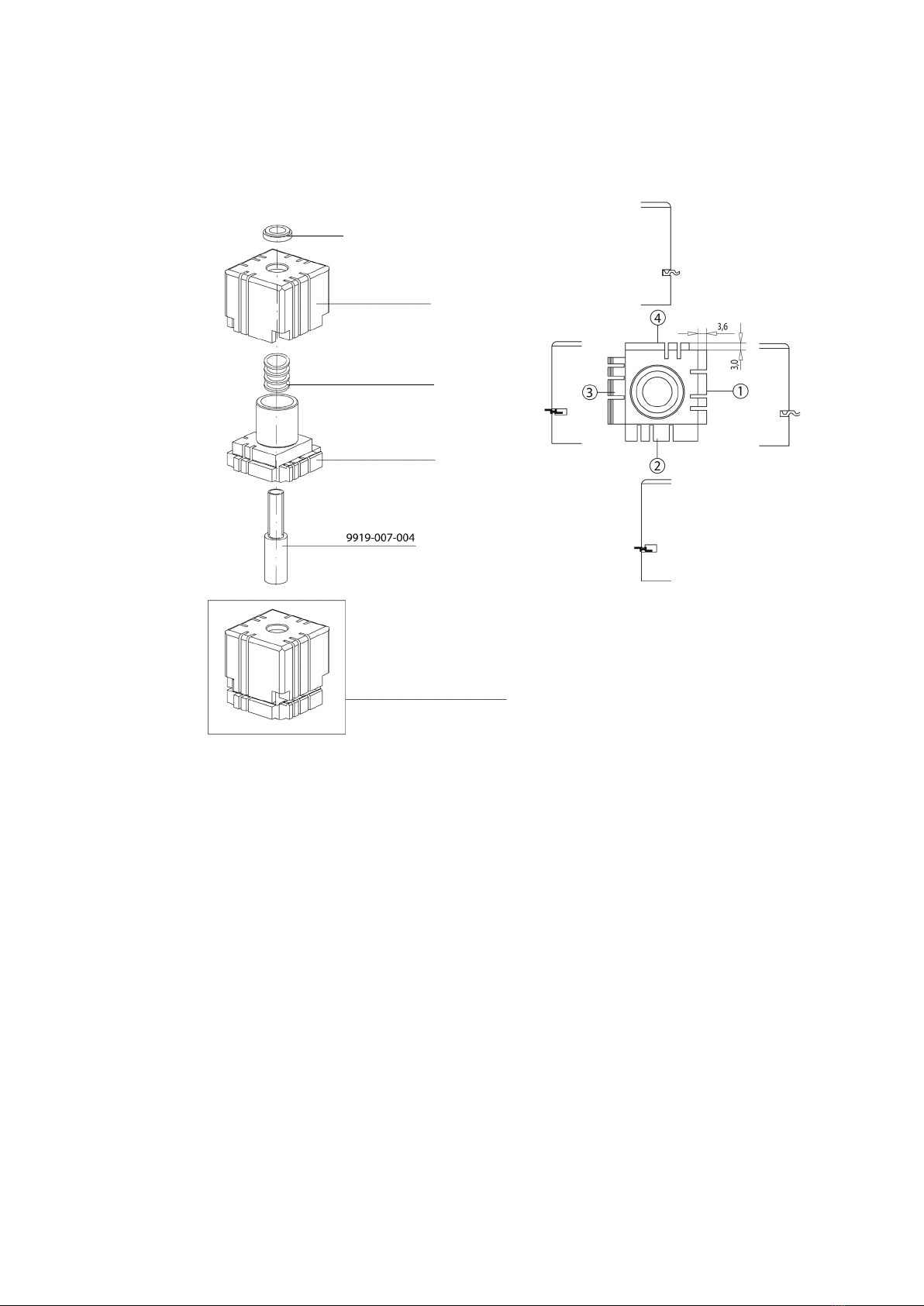
15. Descriptionof the 4-way reversible jaw
The 4–way reversible jaw
Das Spannsystem ermöglicht das Spannen der Schlüssel in Rückenanschlaglage
oder in der Profilausbildung.
Clamping options:
Page 1 Fastening on the back for cutting depths of up to 3.6 mm to the key
back.
Cross-keys up to a length of 120 mm.
Page 2 Profile guidance on the top for keys, which profile frames or incisions do
not facilitate flawless clamping or aligning in the clamping 1 and 4.
Page 3 Profile guidance on the bottom for keys, which profile frames or
incisions do not facilitate flawless clamping or aligning in the clamping
1 and 4.
Page 4 Back fastening position for cutting depths smaller than 3.6 mm to the
key back.
Working instructions
Make sure that the clamping jaws for sample keys and key blank feature the same
clamping positions.
Adjustment of the clamping positions ensues by rotating the entire reversible jaw.
Pic 1
9919-204-004
Druckfeder
9919-010-004
U-Scheibe
Pic 2
9919-010-004
Washer
9919-010-002
Clamping jaw top
9919-204-004
Pressure spring
9919-010-001
Lower part of the reversible vice
Vice complrte
9919-010-000

19
16. Troubleshooting
Machine is not operational
- Check if the mains plug is properly connected to the power grid.
- Switch for restart has not been pressed
- Switch machine `ON – OFF´ has not been pressed
- Safeguard at the mains plug of the machine is defective
Cutter does not work – power supply is all right
- Check if the drive belt is defective. Check ease of motion of the engine shaft and
the cutting shaft.
Drive belt defective
Remove wire brush and machine cap.
Loosen engine mounting below the machine bod (jaw spanner SW 13 mm).
Shift the engine using a clamping device until the original drive belt can be set over
the pulleys. Stretch the belts by shifting the engine.
Re-tighten the engine and re-install the machine cap and the wire brush.
Engine and cutter shaft cannot be rotated
- Contact customer support.
Increased cutting noises; processing quality and accuracy no longer existing
- The processing tool (cutter) must be exchanged.
(Cutter exchange see page 9)
Check and re-adjustment (see page 13)
LED lamp does not glow
- Check if the mains plug is properly connected to the power grid.
- Switch for the lamp has not been pressed.
- Check electronic control gear (electronically qualified person).
Key holder cannot be shifted from basic position to the sensor – cutter
- Check if the stop levers are in basic position and if so, contact the customer
support.
For any other errors please contact our sales department
Tel: 0049 2332 7006-0
Table of contents
Other Borkey Cutter manuals


