Ingersoll-Rand 326 User manual

Refer All Communications to the Nearest
Ingersoll–Rand Office or Distributor.
Ingersoll–Rand Company 2000
Printed in U.S.A.
03533593Form P6702
Edition 6
April, 2000
OPERATION AND MAINTENANCE MANUAL
FOR MODEL 326 HEAVY DUTY CUT–OFF TOOL
The Model 326 Cut–Off Tool is designed for exhaust system replacement work. It quickly
cuts mufflers, tail pipes, sheet metal, nuts and bolts.
Ingersoll–Rand is not responsible for customer modification of tools for applications on
which Ingersoll–Rand was not consulted.
IMPORTANT SAFETY INFORMATION ENCLOSED.
READ THIS MANUAL BEFORE OPERATING TOOL.
IT IS THE RESPONSIBILITY OF THE EMPLOYER TO PLACE THE INFORMATION
IN THIS MANUAL INTO THE HANDS OF THE OPERATOR.
FAILURE TO OBSERVE THE FOLLOWING WARNINGS COULD RESULT IN INJURY.
PLACING TOOL IN SERVICE
•Always operate, inspect and maintain this tool in
accordance with American National Standards
Institute Safety Code for Portable Air Tools
(ANSI B186.1).
•For safety, top performance, and maximum
durability of parts, operate this tool at 90 psig
(6.2 bar/620 kPa) maximum air pressure at the
inlet with 5/16” (8 mm) inside diameter air supply
hose.
•Always turn off the air supply and disconnect the
air supply hose before installing, removing or
adjusting any accessory on this tool, or before
performing any maintenance on this tool.
•Do not use damaged, frayed or deteriorated air
hoses and fittings.
•Be sure all hoses and fittings are the correct size
and are tightly secured. See Dwg. TPD905–1 for a
typical piping arrangement.
•Always use clean, dry air at 90 psig maximum air
pressure. Dust, corrosive fumes and/or excessive
moisture can ruin the motor of an air tool.
•Do not lubricate tools with flammable or volatile
liquids such as kerosene, diesel or jet fuel.
•Do not remove any labels. Replace any damaged
label.
USING THE TOOL
•Always wear eye protection when operating or
performing maintenance on this tool.
•Always wear hearing protection when operating
this tool.
•Keep hands, loose clothing and long hair away
from rotating end of tool.
•Anticipate and be alert for sudden changes in
motion during start up and operation of any power
tool.
•Keep body stance balanced and firm. Do not
overreach when operating this tool. High reaction
torques can occur at or below the recommended
air pressure.
•Tool shaft may continue to oscilate briefly after
throttle is released.
•Air powered tools can vibrate in use. Vibration,
repetitive motions or uncomfortable positions may
be harmful to your hands and arms. Stop using
any tool if discomfort, tingling feeling or pain
occurs. Seek medical advice before resuming use.
•Use accessories recommended by Ingersoll–Rand.
•This tool is not designed for working in explosive
atmospheres.
•This tool is not insulated against electric shock.
•Do not operate tool without the Ingersoll–Rand
steel spark shield furnished with the tool.
The use of other than genuine Ingersoll–Rand replacement parts may result in safety hazards, decreased tool
performance, and increased maintenance, and may invalidate all warranties.
Repairs should be made only by authorized trained personnel. Consult your nearest Ingersoll–Rand Authorized
Servicenter.
F
E
P

2
WARNING LABEL IDENTIFICATION
FAILURE TO OBSERVE THE FOLLOWING WARNINGS COULD RESULT IN INJURY.
Always wear eye protection
when operating or perform-
ing maintenance on this tool.
WARNING WARNING
Always wear hearing
protection when operating
this tool.
Always turn off the air sup-
ply and disconnect the air
supply hose before install-
ing, removing or adjusting
any accessory on this tool,
or before performing any
maintenance on this tool.
WARNING
Air powered tools can vibrate
in use. Vibration, repetitive
motions or uncomfortable po-
sitions may be harmful to your
hands and arms. Stop using
any tool if discomfort, tingling
feeling or pain occurs. Seek
medical advice before resum-
ing use.
WARNING Do not carry the tool by the
hose.
WARNING WARNING
Do not use damaged, frayed
or deteriorated air hoses
and fittings.
WARNING
Keep body stance balanced
and firm. Do not overreach
when operating this tool.
WARNING
Operate at 90 psig (6.2 bar/
620 kPa) Maximum air pres-
sure.
90 psig
(6.2bar/620kPa)
PLACING TOOL IN SERVICE
LUBRICATION
Ingersoll–Rand No. 50
Always use an air line lubricator with this tool.
We recommend the following Filter–Lubricator–Regulator
Unit:
For USA –No. C28–04–FKG0–28
After each eight hours of operation, unless an air–line
lubricator is used, inject 1/2 cc of Ingersoll–Rand No. 50
Oil into the Regulator Assembly (9) before attaching the
hose.
MAIN LINES 3 TIMES
AIR TOOL INLET SIZE
TO
AIR
SYSTEM
TO
AIR
TOOL
LUBRICATOR
REGULATOR FILTER
BRANCH LINE 2 TIMES
AIR TOOL INLET SIZE
DRAIN REGULARLY COMPRESSOR
(Dwg. TPD905–1)
SPECIFICATIONS
Model Free Speed, rpm Wheel Diameter
in mm
326 20,000 2–7/8 73

Adressez toutes vos communications au Bureau
Ingersoll–Rand ou distributeur le plus proche.
Ingersoll–Rand Company 2000
Impriméaux É.U.
MANUEL D’EXPLOITATION ET D’ENTRETIEN
POUR LA TRONÇONNEUSE SÉRIE FORTE MODÈLE 326
NOTE
La tronçonneuse Modèle 326 est destinée aux travaux de remplacement de pots
d’échappement. Elle coupe rapidement les silencieux, les tuyaux d’échappement, les tôles,
les écrous et les boulons.
Ingersoll–Rand ne peut être tenu responsable de la modification des outils par le client
pour les adapter àdes applications qui n’ont pas étéapprouvées par Ingersoll–Rand.
ATTENTION
D’IMPORTANTES INFORMATIONS DE SÉCURITÉSONT JOINTES.
LIRE CE MANUEL AVANT D’UTILISER L’OUTIL.
L’EMPLOYEUR EST TENU DE COMMUNIQUER LES INFORMATIONS
DE CE MANUEL AUX EMPLOYÉS UTILISANT CET OUTIL.
LE NON RESPECT DES AVERTISSEMENTS SUIVANTS PEUT CAUSER DES BLESSURES.
MISE EN SERVICE DE L’OUTIL
•Toujours exploiter, inspecter et entretenir cet outil
conformément au Code de sécuritédes outils
pneumatiques portatifs de l’American National
Standards Institute (ANSI B186.1).
•Pour la sécurité, les performances optimales et la
durabilitémaximale des pièces, cet outil doit être
connectéàune alimentation d’air compriméde
6,2 bar (620 kPa) maximum àl’entrée, avec un
flexible de 8 mm de diamètre intérieur.
•Couper toujours l’alimentation d’air compriméet
débrancher le flexible d’alimentation avant
d’installer, déposer ou ajuster tout accessoire sur
cet outil, ou d’entreprendre une opération
d’entretien quelconque sur l’outil.
•Ne pas utiliser des flexibles ou des raccords
endommagés, effilochés ou détériorés.
•S’assurer que tous les flexibles et les raccords sont
correctement dimensionnés et bien serrés. Voir
Plan TPD905–1 pour un exemple type
d’agencement des tuyauteries.
•Utiliser toujours de l’air sec et propre àune
pression maximum de 6,2 bar. La poussière, les
fumées corrosives et/ou une humiditéexcessive
peuvent endommager le moteur d’un outil
pneumatique.
•Ne jamais lubrifier les outils avec des liquides
inflammables ou volatiles tels que le kérosène, le
gasol ou le carburant d’aviation.
•Ne retirer aucune étiquette. Remplacer toute
étiquette endommagée.
UTILISATION DE L’OUTIL
•Porter toujours des lunettes de protection pendant
l’utilisation et l’entretien de cet outil.
•Porter toujours une protection acoustique pendant
l’utilisation de cet outil.
•Tenir les mains, les vêtements flous et les cheveux
longs, éloignés de l’extrémitérotative de l’outil.
•Prévoir, et ne pas oublier, que tout outil motorisé
est susceptible d’à–coups brusques lors de sa mise
en marche et pendant son utilisation.
•Garder une position équilibrée et ferme. Ne pas se
pencher trop en avant pendant l’utilisation de cet
outil. Des couples de réaction élevés peuvent se
produire à, ou en dessous, de la pression d’air
recommandée.
•L’oscillation des accessoires de l’outil peut
continuer pendant un certain temps après le
relâchement de la gâchette.
•Les outils pneumatiques peuvent vibrer pendant
l’exploitation. Les vibrations, les mouvements
répétitifs et les positions inconfortables peuvent
causer des douleurs dans les mains et les bras.
N’utiliser plus d’outils en cas d’inconfort, de
picotements ou de douleurs. Consulter un médecin
avant de recommencer àutiliser l’outil.
•Utiliser les accessoires recommandés par
Ingersoll-Rand.
•Cet outil n’est pas conçu pour fonctionner dans des
atmosphères explosives.
•Cet outil n’est pas isolécontre les chocs électriques.
•Ne jamais exploiter cet outil sans l’écran
pare–étincelles Ingersoll–Rand fourni avec l’outil.
NOTE
L’utilisation de rechanges autres que les pièces d’origine Ingersoll–Rand peut causer des risques d’insécurité, réduire les
performances de l’outil et augmenter l’entretien, et peut annuler toutes les garanties.
Les réparations ne doivent être effectuées que par des réparateurs qualifiés autorisés. Consultez votre Centre de Service
Ingersoll–Rand le plus proche.
F

4
SIGNIFICATION DES ÉTIQUETTES D’AVERTISSEMENT
ATTENTION
LE NON RESPECT DES AVERTISSEMENTS SUIVANTS PEUT CAUSER DES BLESSURES.
Porter toujours des lunettes
de protection pendant
l’utilisation et l’entretien de
cet outil.
ATTENTION ATTENTION
Porter toujours une
protection acoustique pen-
dant l’utilisation de cet
outil.
Les outils pneumatiques
peuvent vibrer pendant
l’exploitation. Les vibrations,
les mouvements répétitifs et les
positions inconfortables
peuvent causer des douleurs
dans les mains et les bras.
N’utiliser plus d’outils en cas d’in-
confort, de picotements ou
de douleurs. Consulter un
médecin avant de recommencer
àutiliser l’outil.
ATTENTION
Ne pas transporter l’outil
par son flexible.
ATTENTION
ATTENTION
Garder une position équilibrée et
ferme. Ne pas se pencher trop
en avant pendant
l’utilisation de cet outil.
ATTENTION
Utiliser de l’air comprimé
àune pression maximum
de 6,2 bar (620 kPa).
90 psig
(6.2bar/620kPa)
Couper toujours l’alimentation
d’air compriméet débrancher le
flexible d’alimentation avant
d’installer, déposer ou ajuster
tout accessoire sur cet outil, ou
d’entreprendre une opération
d’entretien quelconque sur l’ou-
til.
ATTENTION
ATTENTION
Ne pas utiliser des flexibles ou
des raccords endommagés, ef-
filochés ou détériorés.
MISE EN SERVICE DE L’OUTIL
LUBRIFICATION
Ingersoll–Rand No. 50
Utiliser toujours un lubrificateur avec cet outil. Nous
recommandons l’emploi du filtre–régulateur–lubrificateur
suivant :
É.U. –No. C28–04–FKG0–28
Toutes les huit heures de fonctionnement, sauf si un
lubrificateur d’air compriméest utilisé, injecter 1/2 cm3
d’huile Ingersoll–Rand No. 50 dans l’ensemble régulateur
(9) avant de connecter le flexible.
TUYAUTERIE PRINCIPALE AU
MOINS 3 FOIS LA DIMEN-
SION DE L’ADMISSION D’AIR
DE L’OUTIL
VERS LE
RÉSEAU D’AIR
COMPRIMÉ
VERS
L’OUTIL
PNEU-
MATIQUE
LUBRIFICATEUR
RÉGULATEUR
FILTRE
LIGNE SECONDAIRE AU
MOINS 2 FOIS LA DIMEN-
SION DE L’ADMISSION
D’AIR DE L’OUTIL
VIDANGER
RÉGULIÈREMENT
COMPRESSEUR
(Plan TPD905–1)
SPÉCIFICATIONS
Modèle Vitesse Libre Diamètre de la meule
in mm
326 20.000 2–7/8 73

Toda comunicación se deberádirigir a la oficina o
al distribuidor Ingersoll–Rand más próximo.
Ingersoll–Rand Company 2000
Impreso en EE. UU.
MANUAL DE USO Y MANTENIMIENTO PARA LA HERRAMIENTA DE
CORTE SERVICIO PESADO MODELO 326
NOTA
La herramienta de corte modelo 326 estádiseñada para trabajos de sustitución de sistemas de
escape. Corta rápidamente los silenciadores, tubos de salida, chapa, tuercas y tornillos.
Ingersoll–Rand no aceptaráresponsabilidad alguna por la modificación de las herramientas
efectuada por el cliente para las aplicaciones que no hayan sido consultadas con Ingersoll–Rand.
AVISO
SE ADJUNTA INFORMACIÓN IMPORTANTE DE SEGURIDAD.
LEA ESTE MANUAL ANTES DE USAR LA HERRAMIENTA.
ES RESPONSABILIDAD DE LA EMPRESA ASEGURARSE DE QUE EL OPERARIO
ESTÉAL TANTO DE LA INFORMACIÓN QUE CONTIENE ESTE MANUAL.
EL HACER CASO OMISO DE LOS AVISOS SIGUIENTES PODRÍA OCASIONAR
LESIONES.
PARA PONER LA HERRAMIENTA EN
SERVICIO
•Utilice, examine y mantenga siempre esta
herramienta conforme al código de seguridad para
herramientas neumáticas portátiles de la American
National Standards Institute (ANSI B186.1).
•Para mayor seguridad, rendimiento óptimo y larga
vida útil de las piezas, utilice esta herramienta a
una presión de aire máxima de 90 psig (6,2 bar/
620 kPa) con una manguera de suministro de aire
con diámetro interno de 8 mm.
•Corte siempre el suministro de aire y desconecte la
manguera de suministro de aire antes de instalar,
desmontar o ajustar cualquier accesorio de esta
herramienta, o antes de realizar cualquier
operación de mantenimiento de la misma.
•No utilice mangueras de aire y racores dañados,
desgastados ni deteriorados.
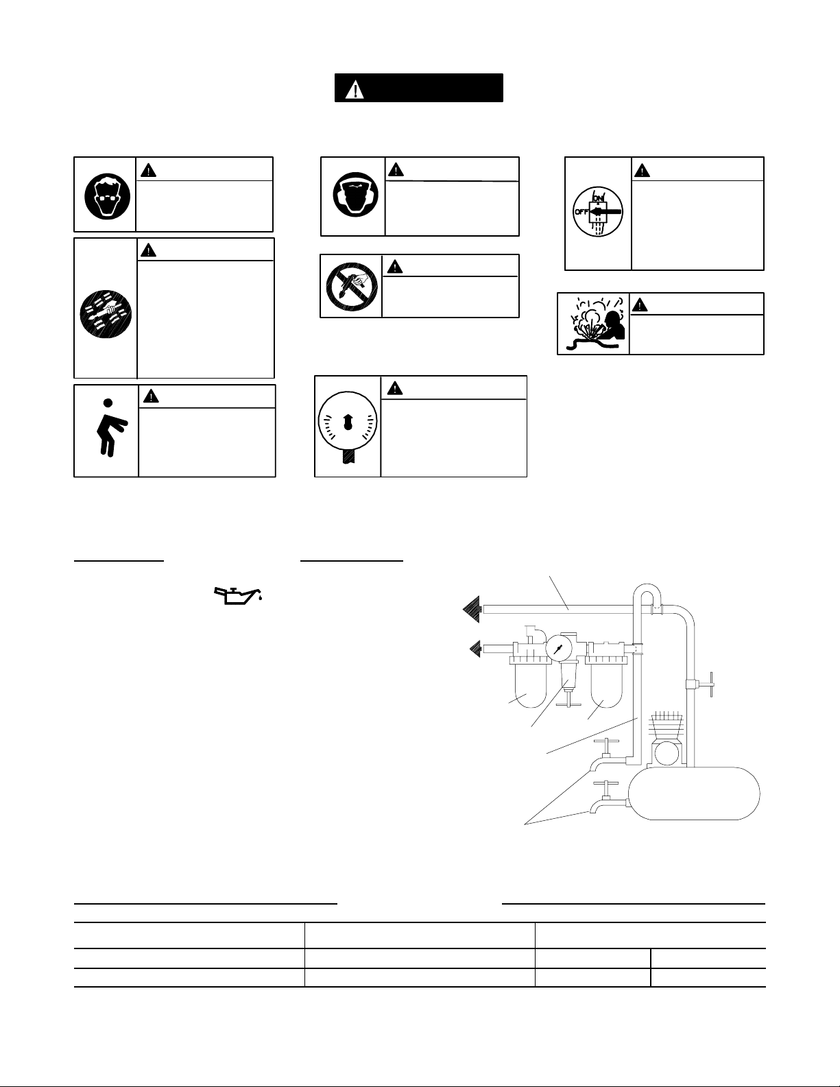
•Asegúrese de que todos los racores y mangueras
sean del tamaño correcto y estén bien apretados.
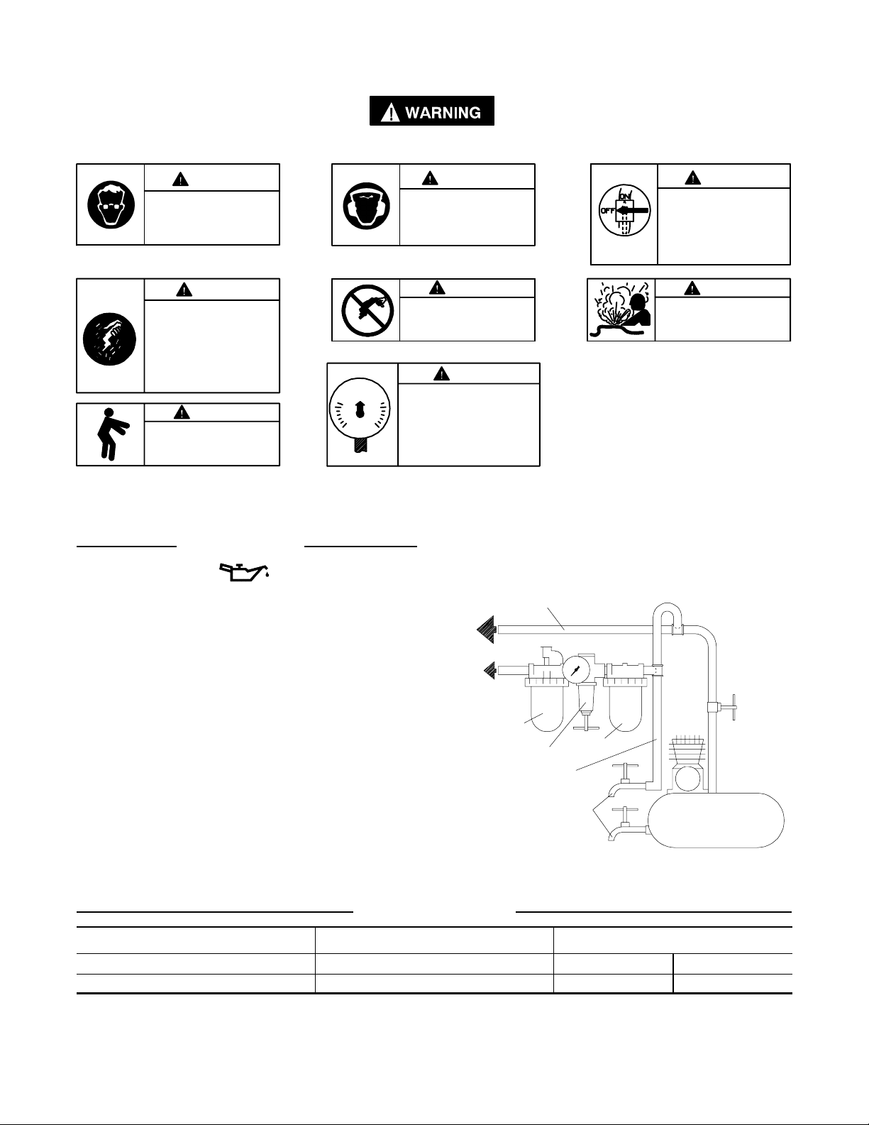
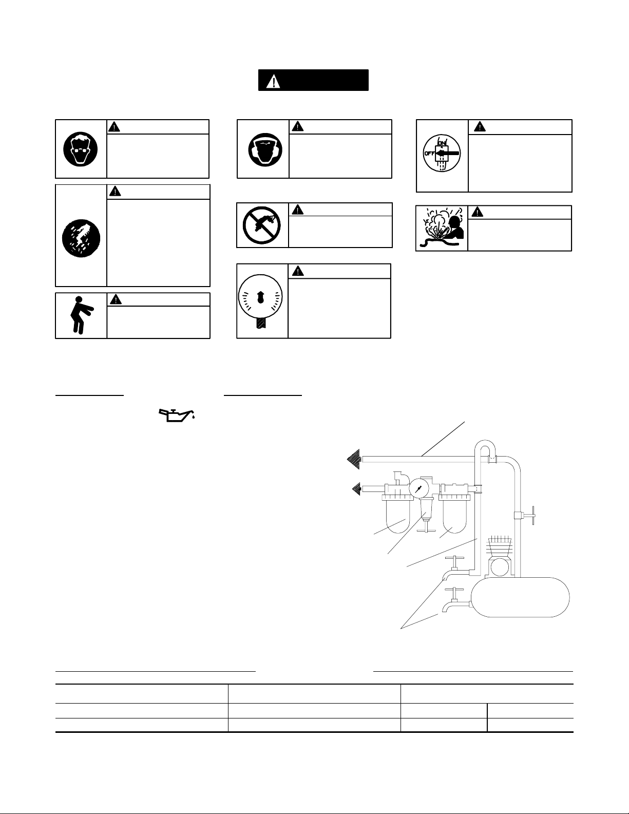
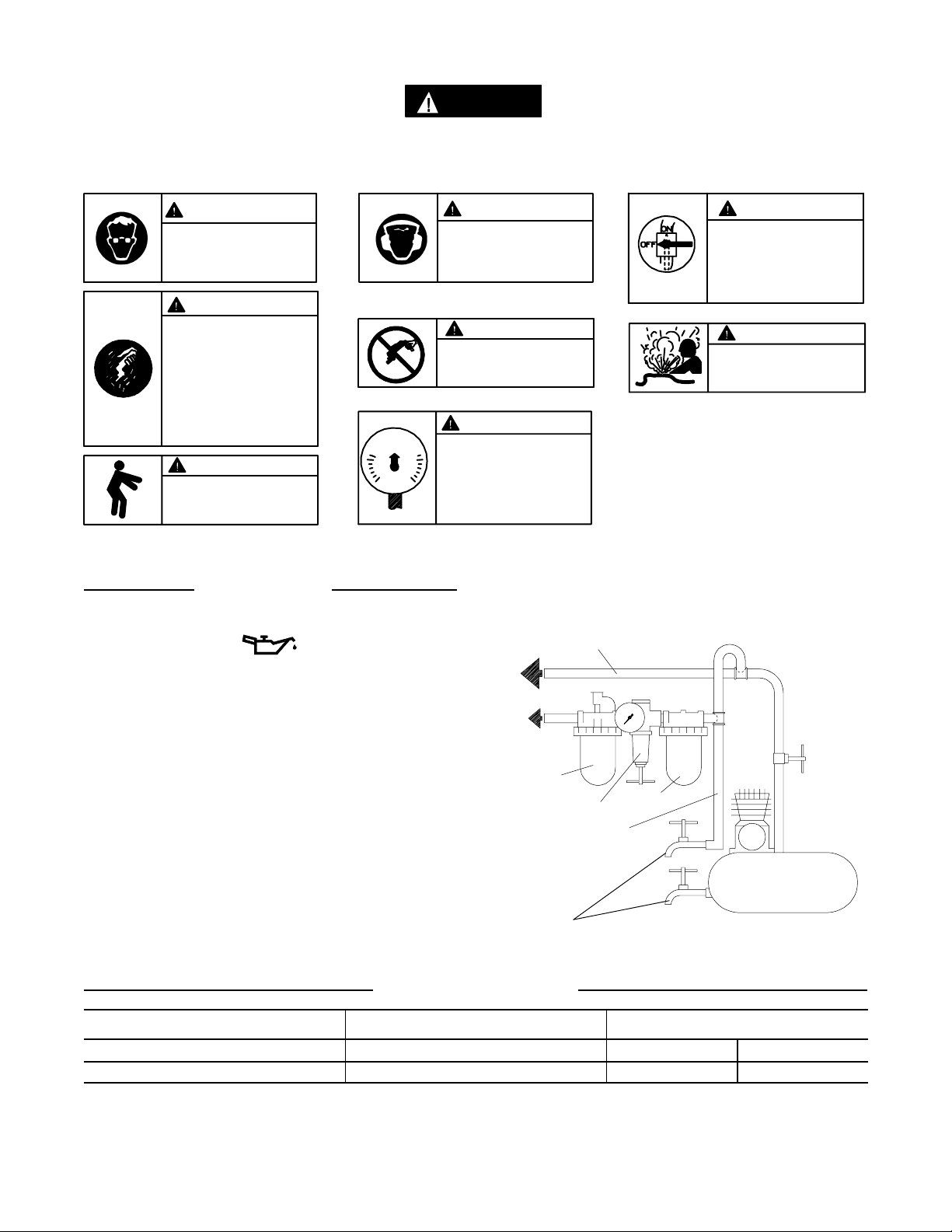
El Esq. TPD905–1 muestra una disposición
característica de las tuberías.
•Use siempre aire limpio y seco a una presión
máxima de 90 psig (6,2 bar/620 kPa). El polvo, los
gases corrosivos y el exceso de humedad pueden
estropear el motor de una herramienta neumática.
•No lubrique las herramientas con líquidos
inflamables o volátiles tales como queroseno, gasoil
o combustible para motores a reacción.
•No saque ninguna etiqueta. Sustituya toda etiqueta
dañada.
UTILIZACIÓN DE LA HERRAMIENTA
•Use siempre protección ocular cuando utilice esta
herramienta o realice operaciones de
mantenimiento en la misma.
•Use siempre protección para los oídos cuando
utilice esta herramienta.
•Mantenga las manos, la ropa suelta y el cabello
largo alejados del extremo giratorio de la
herramienta.
•Anticipe y estéatento a los cambios repentinos en
el movimiento durante la puesta en marcha y
utilización de toda herramienta motorizada.
•Mantenga una postura del cuerpo equilibrada y
firme. No estire demasiado los brazos al manejar la
herramienta. Pueden ocurrir elevados pares de
reacción a la presión recomendada de aire, e
incluso a presiones inferiores.
•El vástago puede continuar oscilando después de
haberse soltado el estrangulador.
•Las herramientas neumáticas pueden vibrar
durante el uso. La vibración, los movimientos
repetitivos y las posiciones incómodas pueden
dañarle los brazos y manos. En caso de
incomodidad, sensación de hormigueo o dolor, deje
de usar la herramienta. Consulte con el médico
antes de volver a utilizarla.
•Utilice únicamente los accesorios recomendados
por Ingersoll–Rand.
•Esta herramienta no ha sido diseñada para
trabajar en ambientes explosivos.
•Esta herramienta no estáaislada contra descargas
eléctricas.
•No utilice esta herramienta sin que tenga instalado
el protector antichispas de acero de Ingersoll–Rand
provisto con la herramienta.
NOTA
El uso de piezas de recambio que no sean las auténticas piezas Ingersoll–Randpuede poner en peligro la seguridad,
reducir el rendimiento de la herramientay aumentar los cuidados de mantenimiento necesarios, asícomo invalidar
todagarantía.
Las reparaciones sólo se deben encomendar a personal debidamente cualificadoy autorizado. Consulte con el centro de
servicio autorizado Ingersoll–Randmás próximo.
E

6
ETIQUETAS DE AVISO
AVISO
EL HACER CASO OMISO DE LOS AVISOS SIGUIENTES PODRÍA OCASIONAR
LESIONES.
ADVERTENCIA
Las herramientas neumáticas
pueden vibrar durante el uso.
La vibración, los movimientos
repetitivos o las posiciones
incómodas podrían dañarle los
brazos y las manos. En caso
de incomodidad, sensación de
hormigueo o dolor, dejar de
usar la herramienta. Consultar
al médico antes de volver a uti-
lizarla.
No coger la herramienta
por la manguera para le-
vantarla.
ADVERTENCIA
Mantener una postura del cuerpo
equilibrada y firme. No estirar de-
masiado los brazos al manejar la
herramienta.
Manejar la herramienta a una
presión de aire máxima de 90
psig (6,2 bar/620 kPa).
90 psig
(6.2bar/620kPa)
Cortar siempre el suministro
de aire y desconectar la man-
guera de suministro de aire
antes de instalar, retirar o ajus-
tar cualquier accesorio de esta
herramienta, o antes de reali-
zar cualquier operación de
mantenimiento de la misma.
No utilizar mangueras de aire
y accesorios dañados, des-
gastados ni deteriorados.
ADVERTENCIA
ADVERTENCIA
ADVERTENCIA
ADVERTENCIA
ADVERTENCIA
ADVERTENCIA
Use siempre protección para
los oídos cuando utilice esta
herramienta.
Use siempre protección ocular
cuando utilice esta herramienta
o realice operaciones de
mantenimiento en la misma.
PARA PONER LA HERRAMIENTA EN SERVICIO
LUBRICACIÓN
Ingersoll–Rand Nº50
Use siempre un lubricante de aire con esta herramienta.
Recomendamos el siguiente conjunto de
filtro–lubricador–regulador:
EE. UU. –No. C28–04–FKG0–28
Después de cada ocho horas de funcionamiento, a
menos que se use un lubricador de línea de aire, inyecte
1/2 cc de aceite Ingersoll–Rand Nº50 en el regulador (9)
antes de acoplar la manguera.
TUBERÍAS PRINCIPALES 3
VECES EL TAMAÑO DE
ENTRADA DE HERRAMIENTA
NEUMÁTICAAL SISTEMA
NEUMÁTICO
A LA
HERRA–
MIENTA
NEUMÁTICA
LUBRICADOR
REGULADOR FILTRO
TUBERÍA DE RAMAL
2 VECES EL TAMAÑO
DE ENTRADA DE
HERRAMIENTA
NEUMÁTICA
PURGAR
PERIÓDICAMENTE
COMPRESOR
(Esq. TPD905–1)
ESPECIFICACIONES
Modelo Velocidad en Vacio Diámetro de la rueda
in mm
326 20.000 2–7/8 73

Envie Todos os Comunicados Para o Distribuidor
ou Escritório da Ingersoll–Rand Mais Próximo.
Ingersoll–Rand Company 2000
Impresso nos E.U.A.
MANUAL DE FUNCIONAMENTO E MANUTENÇÃO
PARA A MÁQUINA DE DISCO DE CORTE PARA
TRABALHO PESADO MODELO 326
AVISO
A Máquina de Disco de Corte Modelo 326 éconcebida para tarefas de substituição de
sistemas de escape. Corta rapidamente silenciosos, tubos de escape, chapas metálicas,
porcas e parafusos.
A Ingersoll–Rand não éresponsável por modificações, feitas pelo cliente em ferramentas, nas
quais a Ingersoll–Rand não tenha sido consultada.
ADVERTÊNCIA
INFORMAÇÃO DE SEGURANÇA IMPORTANTE EM ANEXO.
LEIA ESTE MANUAL ANTES DE OPERAR A FERRAMENTA.
ÉDA RESPONSABILIDADE DO EMPREGADORCOLOCAR A INFORMAÇÃO
DESTE MANUAL NAS MÃOS DO OPERADOR.
O NÃO CUMPRIMENTO DAS SEGUINTES ADVERTÊNCIAS PODE
RESULTAR EM FERIMENTOS.
COLOCANDO A FERRAMENTA EM
FUNCIONAMENTO
•Sempre opere, inspeccione e mantenha esta
ferramenta de acordo com o Código de Segurança
do Instituto Americano de Padrões Nacionais para
Ferramentas Pneumáticas Portáteis (ANSI
B186.1).
•Para segurança, máximo desempenho e máxima
durabilidade das peças, opere esta ferramenta com
uma pressão de ar máxima de 6,2 bar/620 kPa
(90 psig) na entrada da mangueira de alimentação
de ar com diâmetro interno de 8 mm (5/16”).
•Desligue sempre a alimentação de ar e desconecte a
mangueira de alimentação de ar antes de instalar,
remover ou ajustar qualquer acessório nesta
ferramenta, ou antes de executar qualquer serviço
de manutenção nesta ferramenta.
•Não use mangueiras de ar ou adaptadores
danificados, gastos ou deteriorados.
•Certifique–se de que todas as mangueiras e
adaptadores sejam do tamanho correcto e estejam
apertados com firmeza. Veja o Desenho TPD905–1
para um arranjo típico de tubagem.
•Use sempre ar seco e limpo com pressão máxima
de 90 psig. Pó, fumos corrosivos e/ou humidade
excessiva podem arruinar o motor de uma
ferramenta pneumática.
•Não lubrifique as ferramentas com líquidos
inflamáveis ou voláteis tais como querosene, diesel
ou combustível de jactos.
•Não remova nenhum rótulo. Reponha qualquer
rótulo danificado.
USANDO A FERRAMENTA
•Use sempre óculos de protecção quando estiver
operando ou executando serviço de manutenção
nesta ferramenta.
•Use sempre protecção contra ruído ao operar esta
ferramenta.
•Mantenha as mãos, partes do vestuário soltas e
cabelos compridos afastados da extremidade em
rotação.
•Antecipe e esteja alerta a mudanças repentinas no
movimento quando ligar e operar qualquer
ferramenta motorizada.
•Mantenha a posição do corpo equilibrada e firme.
Não exagere quando operar esta ferramenta.
Torques de reacção elevados podem ocorrer na ou
abaixo da pressão de ar recomendada.
•O eixo da ferramenta pode continuar a girar
brevemente após a pressão ter sido aliviada.
•Ferramentas accionadas pneumáticamente podem
vibrar em uso. Vibração, movimentos repetitivos
ou posições desconfortáveis podem ser prejudiciais
às mãos e aos braços. Pare de usar a ferramenta
caso ocorra algum desconforto, sensação de
formigueiro ou dor. Procure assistência médica
antes de retornar ao trabalho.
•Use acessórios recomendados pela Ingersoll–Rand.
•Esta Ferramenta não foi concebida para trabalhos
em atmosferas explosivas.
•Esta Ferramenta não estáisolada contra choques
eléctricos.
•Não opere esta ferramenta sem a Proteção em Aço
contra Faíscas da Ingersoll–Rand fornecida com a
ferramenta.
AVISO
O uso de peças de substituição que não sejam genuinamente da Ingersoll–Rand podem resultar em riscos de segurança,
diminuição do desempenho da ferramenta, aumento da necessidade de manutenção e pode invalidar todas as garantias.
As reparações devem ser feitas somente por pessoal treinado autorizado. Consulte o Centro de Serviços da
Ingersoll–Rand mais próximo.
P

8
IDENTIFICAÇÃO DO RÓTULO DE ADVERTÊNCIA
ADVERTÊNCIA
O NÃO CUMPRIMENTO DAS SEGUINTES ADVERTÊNCIAS PODE
RESULTAR EM FERIMENTOS.
Use sempre óculos de
protecção quando estiver
operando ou executando algum
serviço de manutenção nesta
ferramenta.
ADVERTÊNCIA
Use sempre protecção contra o
ruído ao operar esta ferramenta. Desligue sempre a alimentação
de ar e desconecte a mangueira
de alimentação de ar antes de
instalar, remover ou ajustar
qualquer acessório nesta
ferramenta, ou antes de
executar algum serviço de
manutenção nesta ferramenta.
Ferramentas accionadas
pneumáticamente podem vibrar
em uso. Vibração, movimentos
repetitivos ou posições
desconfortáveis podem ser
prejudiciais às mãos e aos
braços. Pare de usar a
ferramenta caso ocorra algum
desconforto, sensação de
formigueiro ou dor. Procure
assistência médica antes de
retornar ao trabalho.
Não carregue a ferramenta
segurando na mangueira. ADVERTÊNCIA
Não use mangueiras de ar ou
adaptadores danificados,
gastos ou deteriorados.
Mantenha a posição do corpo
equilibrada e firme. Não
exagere quando operar esta
ferramenta. Torques de reacção
elevados podem ocorrer sob a
pressão de ar recomendada.
Opere com pressão do ar Máxima
de 90–100 psig (6,2–6,9 bar).
90 psig
(6.2bar/620kPa)
ADVERTÊNCIA ADVERTÊNCIA
ADVERTÊNCIA
ADVERTÊNCIA
ADVERTÊNCIA
ADVERTÊNCIA
COLOCANDO A FERRAMENTA EM FUNCIONAMENTO
LUBRIFICAÇÃO
Ingersoll–Rand No. 50
Use sempre um lubrificador de ar de linha com estas
ferramentas. Nós recomendamos a seguinte unidade
Filtro–Lubrificador–Regulador:
E.U.A. –No. C28–04–FKG0–28
Após cada oito horas de funcionamento, a menos que
esteja a ser utilizado um lubrificador de linha de ar, injecte
1/2 cc de Óleo Ingersoll–Rand Nº50 no Conjunto
Regulador (9) antes de ligar a mangueira de ar.
LINHAS PRINCIPAIS 3 VEZES O TAMANHO DA
ENTRADA DA FERRAMENTA PNEUMÁTICA
PARA
SISTEMA DE AR
PARA
FERRAMENTA
PNEUMÁTICA
LUBRIFICADOR
REGULADOR FILTRO
LINHA RAMIFICADA
2 VEZES O TAMANHO
DA ENTRADA DA
FERRAMENTA
PNEUMÁTICA
DRENE
REGULARMENTE
COMPRESSOR
(Desenho TPD905–1)
ESPECIFICAÇÕES
Model Velocidade Livre Diâmetro da Mó
in mm
326 20.000 2–7/8 73

MAINTENANCE SECTION
9
(Dwg. TPB747–2)

MAINTENANCE SECTION
10
PART NUMBER FOR ORDERING PART NUMBER FOR ORDERING
1Motor Housing . . . . . . . . . . . . . . . . . . . . . . . . . . . . . . . 326–40 9 Regulator Assembly . . . . . . . . . . . . . . . . . . . . . . . . . . . 326–250
*Warning Label . . . . . . . . . . . . . . . . . . . . . . . . . . . WARNING–20–99 10 Steel Spark Shield . . . . . . . . . . . . . . . . . . . . . . . . . . . . 326–931
2 Throttle Valve . . . . . . . . . . . . . . . . . . . . . . . . . . . . . . . 326–50 12 Spark Shield Lock Nut . . . . . . . . . . . . . . . . . . . . . . . . 326–27
3 Throttle Valve Stem Assembly . . . . . . . . . . . . . . . . . . 326–A152 13 Motor Assembly . . . . . . . . . . . . . . . . . . . . . . . . . . . . . 326–A53
4Valve Stem Seal . . . . . . . . . . . . . . . . . . . . . . . . . . 326–160 14 Wheel Flange . . . . . . . . . . . . . . . . . . . . . . . . . . . . . . . . 326–337
5Plunger Seal . . . . . . . . . . . . . . . . . . . . . . . . . . . . . 326–159 15 Wheel Flange Screw . . . . . . . . . . . . . . . . . . . . . . . . . . 326–338
6 Throttle Valve Spring . . . . . . . . . . . . . . . . . . . . . . . . . . 326–51 16 Arbor Wrench . . . . . . . . . . . . . . . . . . . . . . . . . . . . . . . 326–69
7 Throttle Lever Assembly . . . . . . . . . . . . . . . . . . . . . . . 326–A400 17 Flange Screw Wrench . . . . . . . . . . . . . . . . . . . . . . . . . 326–68
7A Throttle Lever Latch . . . . . . . . . . . . . . . . . . . . . . 326–402 * Nameplate . . . . . . . . . . . . . . . . . . . . . . . . . . . . . . . . . . 326–301
7B Latch Spring . . . . . . . . . . . . . . . . . . . . . . . . . . . . . 326–405 * Nameplate Drive Screw (2) . . . . . . . . . . . . . . . . . . . . . 326–302
7C Latch Pin . . . . . . . . . . . . . . . . . . . . . . . . . . . . . . . 326–739
8Throttle Lever Pin . . . . . . . . . . . . . . . . . . . . . . . . . . . . 326–120
* Not illustrated.

11
MAINTENANCE SECTION
Always wear eye protection when operating or
performing maintenance on this tool.
Always turn off the air supply and disconnect the air
supply hose before installing, removing or adjusting
any accessory on this tool, or before performing any
maintenance on this tool.
DISASSEMBLY
General Instructions
1. Do not disassemble the tool any further than
necessary to replace or repair damaged parts.
2. Whenever grasping a tool or part in a vise, always use
leather–covered or copper–covered vise jaws to
protect the surface of the part or tool and help prevent
distortion. This is particularly true of threaded
members and housings.
3. Do not remove any part which is a press fit in or on a
subassembly unless the removal of that part is
necessary for repairs or replacement.
4. Do not disassemble the tool unless you have a
complete set of new gaskets and O–rings for
replacement.
Disassembly of the Tool
1. Using the Arbor Wrench (16) to keep the spindle from
rotating, use the Flange Screw Wrench (17) to loosen
and remove the Wheel Flange Screw (15), Wheel
Flange (14) and the Cut–Off Disc.
2. Using a wrench on the Spark Shield Lock Nut (12),
loosen the Nut by rotating it counterclockwise.
3. Using a wrench on the flats located on the large body
of the Motor Assembly (13), unscrew the Motor
Assembly and separate it from the Motor Housing (1).
Remove the Steel Spark Shield (10) and Shield Lock
Nut.
4. Unscrew and remove the Power Regulator (9).
5. Press the Throttle Lever Pin (8) out of the Motor
Housing and Throttle Lever Assembly (7). Remove
the Throttle Lever Assembly.
6. Using a wrench on the hex of the Throttle Valve (2),
unscrew the Valve and remove the Throttle Valve
Stem Assembly (3) and Throttle Valve Spring (6).
ASSEMBLY
General Instructions
1. Always press on the inner ring of a ball–type bearing
when installing the bearing on a shaft.
2. Always press on the outer ring of a ball–type bearing
when pressing the bearing into a bearing recess.
3. Whenever grasping a tool or part in a vise, always use
leather–covered or copper–covered vise jaws. Take
extra care not to damage threads or distort housings.
4. Always clean every part and wipe every part with a
thin film of oil before installation.
5. Check every bearing for roughness. If an open bearing
must be cleaned, wash it thoroughly in a clean,
suitable, cleaning solution and dry with a clean cloth.
Sealed or shielded bearings should not be cleaned.
Work grease into every open bearing before
installation.
6. Apply a film of O–ring lubricant to every O–ring
before installation.
Assembly of the Tool
1. Insert the Throttle Valve Spring (6), large end leading,
followed by the Throttle Valve Stem Assembly (3)
into the Motor Housing (1).
2. Thread the Throttle Valve (2) into the Housing and
tighten it with a wrench.
3. Position the Throttle Lever Assembly (3) on the
Housing and press the Throttle Lever Pin (8) into the
Lever and Housing to secure the Lever in position.
4. Thread the Spark Shield Lock Nut (12) onto the
Motor Assembly (13) as near to the wheel end as
possible.
5. Place the Steel Spark Shield (10) on the Motor
Assembly against the Lock Nut.
6. Thread the Motor Assembly into the Motor Housing
and using a wrench on the motor flats, tighten the
Motor in the Housing.
7. Orient the Shield to the desired position against the
Motor Housing. Rotate the Lock Nut
counterclockwise until it locks the Shield against the
Motor Housing.
8. Install the Regulator Assembly (9) at the rear of the
Motor Housing and tighten it with a wrench.
9. Install a Cut–Off Disc on the arbor of the motor and
secure it with the Wheel Flange (14) and Wheel
Flange Screw (15).

MAINTENANCE SECTION
TROUBLESHOOTING GUIDE
Trouble Probable Cause Solution
Loss of power Low air pressure Check the air supply. For top performance, the air
pressure must be 90 psig (6.2 bar/620 kPa) at the
inlet of the tool.
Clogged Power Regulator Clean the Power Regulator in a clean, suitable
cleaning solution. If it cannot be cleaned, replace
it.
Worn Throttle Valve Replace the Throttle Valve.
Leaky Throttle Valve Worn Throttle Valve Install a new Throttle Valve.
Excessive runout Bent Arbor Replace the Motor Assembly.
SAVE THESE INSTRUCTIONS. DO NOT DESTROY.
Other manuals for 326
1
Table of contents
Languages:
Other Ingersoll-Rand Cutter manuals
Popular Cutter manuals by other brands

Silca
Silca Delta 2000 AY operating manual

Bosch
Bosch AdvancedCut 18 Original instructions

ESAB
ESAB Precision Plasmarc Installation, operation and maintenance manual

probst
probst AL-90 operating instructions

Full Spectrum Laser
Full Spectrum Laser HL40-5g Hobby Advanced user manual

Makita
Makita DMC300 instruction manual