Truxta QUADro Q300G Installation and operation manual

MACHINE MODELS
QUADro
Q300G & Q450G
SERIAL Numbers from Q181018
OPERATOR MANUAL & PARTS LIST
Op Manual - Part No 800/17000

Declaration of Conformity .............................................................3
Warning, Symbols & Decals …………………………...……….…..……..4-5
General Safety / Health & Safety ...............................................6 -7
Machine Specification ………...........................................................8
Operating Instructions; - Petrol .................................................... 9
(Pre-Start Checks, Start and Stop Procedures)
Service & Maintenance - Petrol ..............................................10-12
Service - Pump Control Settings & Adjustment …….…...…….…..13
Parts List & Assembly
QUADRO Top Frame Parts List ……..……..…….….…………..14– 15
QUADRO Front Assembly Parts List ……..….……...…………..16– 17
QUADRO Rear Assembly Parts List ...…………….…..……….…18—19
Attachments Parts List
Flat Bed - Log Poles - Greedy-Boards - Skip Handle ……….......20-21
Warranty Registration ..................................................................23
TABLE OF CONTENTS
Page 2

Page 3
DECLARATION OF CONFORMITY
EC DECLARATION OF CONFORMITY
We , Tufftruk Ltd, Sheen, nr. Buxton, Derbyshire, SK17 0EU, GB, hereby certify that if the
product described within this certificate is bought from an authorised Tufftruk dealer within the
EEC, it conforms to the following EEC directives: 2006/42/CE (This directive replaces directive
98/37/EC), Electromagnetic Compatibility Directive 2004/108/CE (as amended by 89/336/EEC,
92/31/EEC & 93/68 EEC).
The Waste Electrical and Electronic Equipment (WEEE) 2002/96/CE, the low voltage directive
2006/95/CE, BS EN ISO 12100-1:2003 Safety of machinery and associated harmonised standards,
where applicable.
Noise emissions conform to directive 2000/14/EC Annex VI, for machines under article 12 the
notified body is AV Technology Limited, AVTECH House, Birdhall Lane, Cheadle Heath,
Stockport, Cheshire, SK3 0XU, GB.
Noise Technical Files are held at the Tufftruk Head Office address stated above.
Declare that the following equipment conforms to the Directive: -
2000/14/EC (as amended) of the European Parliament and of the council on the approximation
of the laws of the Member States relating to the
Noise Emission in the Environment by
Equipment for Use Outdoors.
Equipment Category: Pedestrian Power Barrow
Product Name: TRUXTA
Model: Q 300G / Q450G
Serial No:
The technical documentation is held by: TUFFTRUK Ltd Address above
The conformity assessment procedure followed was in according with annex VI of the Directive.
Notified Body: AV Technology Ltd SK9 3RW
Measured Sound Power Level: 94 dB (LWA)
Guaranteed Sound Power Level: 96 dB (LWA)
A copy of this certificate has been submitted to the European Commission and to EU Member State,
United Kingdom
Place
of Declaration Date Signed By Position in Company
Tufftruk Ltd 01/09/2017 Ronald Blackhurst Managing Director
Name and address of manufacturer or Authorised representative: Tufftruk Ltd SK17 0EU

NOISE LIMITS
ALWAYS READ THE
MANUAL
WEAR APPROPRIATE PPE
WARNING SYMBOLS & DECALS
Page 4
SKIP RETAINER
CATCH
CRUSH ZONE
WARNING DIRECTION OF TRAVEL
PAYLOAD
LIFTING POINTS
UN-LADEN
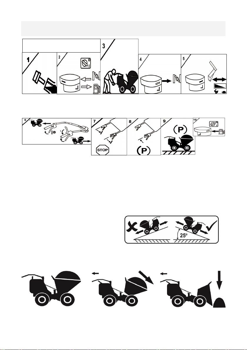
1. Always check oil level before starting.
2. Choke controls starting.
3. Pull to start
TO MOVE TRUXTA
6/7. Press yellow dead-man handle on right handle down for any movement.
Right handle lower lever for forward motion . Left handle lower lever for reverse motion.
8. TO STOP / PARK
Release dead-man handle to stop.
Release lower forward / reverse levers
9. Ideally park on flat surface.
10. Engine OFF switch & close fuel tap when transporting to prevent
carburettor flooding.
ON INCLINES
Do not use TRUXTA on inclines / ramps above 25°
Do Not travel forwards down inclines.
When Tipping always position on a flat Use skip tip handle to release the skip. The skip has a 2-stage tip
action to fully empty
Stage 1 Stage 2
OPERATOR INSTRUTIONS
4. Adjust choke controls when engine is running.
5. Engine rpm control lever
Page 5
OPERATOR INSTRUCTIONS
WARNING SYMBOLS & DECALS

Page 6
For your own personal protection and for the safety of those around you, please read and
ensure you fully understand the following safety information.
It is the responsibility of the operator to ensure that he/she fully understands how to operate
this equipment safely.
• This equipment is heavy and must not be lifted single-handedly, GET HELP and use suitable lifting equipment.
• Cordon off the work area and keep members of the public and unauthorized personnel at a safe distance.
• Personal Protective Equipment (PPE) must be worn by the operator when ever this equipment is being used (see
Health & Safety).
• Make sure you know how to safely switch this machine OFF before you switch it ON in case you get into difficulty.
• Always switch OFF the engine before transporting, moving it around the site or servicing it.
• During use the enginebecomes very hot; allow the engine to cool before touchingit. Never leave the engine running
and unattended.
• Never remove or tamper with any guardsfitted, they are there for your protection.
• Always check guardsfor condition andSecurity, if any is damaged or missing, DO NOT USE THE TRUXTA until
the guard has been replaced or repaired.
• Do not operate the machine when you are ill, feeling tired, or when under the influence of alcohol or drugs.
• Do not stand the machine on end with the engine running.
• Do not use the TRUXTA to transport people.
• Do not release the brake suddenly when travelling forward at speed with a heavy load as themachine may topple
forward.
• (Brake off). Close the throttle if necessaryso that engine braking controls the speed.
Always ensure that when moving downwards on a hill, the machine is travelling in reverse.
• Before refuelling, switch off the engine and allowit to cool.
When refuelling, DO NOT smoke or allow naked flames in the area.
• Spilt fuelmust be made safe immediately, by usingsand. If fuel is spilt on your clothes, change them.
• Store petrol/diesel in an approved, purpose made container away from heat and ignition sources.
• If fuel is spilt when re-fuelling the tank, wipe off the excess and wait 2minutes before re-starting.
• Always travelin a straight line.When travelling across a graduated slope, always travel in a forward direction,
maximum gradient 6 degrees (10%) when travelling across with a TRUXTA.
GENERAL SAFETY

Page 7
VIBRATION
Some vibration from the operation is transmitted through the handle to the operator’s
hands.
DO NOT exceed the maximum usage times. (See Technical Data section)
PPE (Personal Protective Equipment).
Suitable PPE must be worn when using this equipment i.e. Safety Goggles, Gloves, Ear
Defenders, Dust Mask and Steel Toe capped.
Footwear. Wear clothing suitable for the work you are doing. Tie back long hair and
remove any jewellery which may catch in the equipment’s moving parts.
Petrol Machines.
Do not ingest fuel or inhale fuel vapours and avoid contact with your skin. Wash fuel
splashes immediately. If you get fuel in your eyes,
Irrigate with copious amounts of water and seek medical attention as soon as possible.
Exhaust Fumes
Do not operate the TRUXTA indoors or in a confined space, make sure the work area
is adequately ventilated.
HEALTH AND SAFETY
Safe Disposal.
Instructions for the protection of the environment.
The machine contains valuable materials.
Take the discarded apparatus and accessories to the relevant recycling
facilities.
ENVIRONMENT

Page 8
SPECIFICATION
Model QUADRO
Q300G
QUADRO
Q450G
Engine/Motor/
Power kW/hp
HONDA GX 160
3.6 / 4.8
HONDA GX 200
4.1 / 5 .5
Fuel Type Unleaded
Petrol 4 stroke
Fuel Capacity 3.1 litres/ 0.682 gal 3.1 litres/ 0.682 gal
Width x Length x
Height
730mm x 1640mm x 976mm
29 Inch x 65 Inch x 38 Inch
850mm x 1640mm x 976mm
34 Inch x 65 Inch x 38 Inch
Max Payload
300 kg
660 lbs
7ft 3/ 0.2m3
450 kg
990 lbs
10.6ft3/ 0.3m3
Unladen Weight 137kg
302lbs
147kg
324 lbs
Working Gradient
See general safety notes 25° 25°
Drive & Controls Hydrostatic System
Brake System Dynamic braking with
100% fail-safe emergency stop/park brake
Standard
Fitment Tyres
Flotation with option for
turf tyres
Flotation with option for
turf tyres
Travel Speed
Forward
Reverse
Forward 0—4 mph/ 6.44 kph
Reverse 0—2 mph/ 3.22 kph
Noise Level (db) < 96
Hand Arm
Vibration 2.5 m/s²

Page 9
OPERATING THE TRUXTA
1. Start the engine by putting the throttle to the run position and turning the
ignition on. (use choke if cold)
2. Grip the dead man lever and hold it down.
3. Use the forward and reverse levers to control direction of travel and speed.
4. Never press both levers at once or whilst the dead man is released as this will
cause unnecessary strain on the operation cables
EMPTYING THE SKIP
1. Stop the machine by releasing the Drive Lever followed by releasing the dead
man Brake Lever.
2. Once the machine has become stationary, pull the Skip Release Lever and the
Skip will tip forwards disposing of its contents.
3. When the Skip is empty, push back to its original position. The Skip will lock
into place automatically.
4. Do not use the skip as a levelling blade as this could result in damage to the
tipping under carriage.
PRE START UP INSPECTION
The following pre-start-up inspection must be performed before the start of each work
session or after every four hours of use, whichever is first.
Please refer to the service section for detailed guidance.
If any fault is discovered, the TRUXTA must not be used until the fault is rectified.
1. Thoroughly inspect the TRUXTA for signs of damage.
2. Check components are present and secure.
3. Check fluid lines, hoses filler openings, drain plugs and any other areas for
signs of leakage.
Fix any leaks before operating.
4. Check the engine oil and fuel levels and top up as necessary.
5. Check the tyre pressures and top up as necessary.
PETROL - OPERATING INSTRUCTIONS
If it is necessary to travel down a slope of more than 5° when fully laden, ensure that the
machine is turned round and reverse down the slope.

Page 10
OPERATING THE PETROL TRUXTA
Start the engine by putting the throttle to the run position and turning the igni-
tion on. (use choke if cold)
Grip the dead man lever and hold it down.
Use the forward and reverse levers to control direction of travel and speed.
Never press both levers at once or whilst the dead man is released as this will cause
unnecessary damage to the machine.
Release the dead man to stop.
SERVICE & MAINTENANCE - PETROL

Page 11
Hydrostatic Oil
Top up if oil is below minimum level when machine is cold. If there are any
signs of leakage, stop using the machine and contact your local dealer or
Tufftruk Ltd. Refill with motor oil —20W50.
Machine Cleaning
Clean the machine after it has been used to prevent the collection of hardened
debris. Hardened debris is very difficult to remove. To clean it use an old brush
or hand brush with water. Never pressure wash or hose down the engine or
electric motor housing. Clean only with a cloth or compressed air.
Air Filter - If it is dirty, proceed as follows:-
Foam Element - Wash the element in a solution of washing-up liquid and water.
Allow the element to dry, then soak in clean engine oil and squeeze out the
excess oil. If the engine smokes during start-up then too much oil has been left
on the foam.
Paper Element - Tap the element on a hard surface or blow from inside using
compressed air to remove any excess dust within the filter. Replace every 200
hours or if it is extremely dirty.
Transmission Drive Chains
Clean and lubricate the 2 transmission drive chains once a year.
Tyre Pressure
Truxta tyre pressure should be regularly checked and maintained at 25PSI
(flotation and turf tyres)
SERVICE & MAINTENANCE - PETROL
ROUTINE MAINTENANCE
Every
20
hours
Every
50
hours
Every 200 hours
ENGINE OIL
CHANGE
CHECK CONDITION
AIR FILTER
CLEAN / REPLACE
SPARK PLUG CHANGE
SPARK PLUG AND OIL DATA
Engine
Oil Type
Qty
(gals) Fuel Type Capacity
(gals)
Spark
Plug
Electrode
Gap (mm)
Hydrostatic
Transmission
Oil
PETROL
HONDA
S.A.E
10W30 0.17
UNLEADED
SP95 only -EU
Octane 91 min US
0.53 BPR5
ES 0.07-0.8 20W50
Page 12
SERVICE & MAINTENANCE - PETROL
REGULAR SERVICE - HONDA
Each Use First
Month
or 20 hrs
Every 3
months
or 50 hrs
Every 6
months
or 100
hrs
Every year
or 300 hrs
Perform at every indicated month or
operang hour interval, whichever comes
rst
ITEM
ENGINE OIL Check level o
Change oo
REDUCTION CASE
OIL applicable
Check level o
Change oo
AIR FILTER Check
Clean o * o *
Replace o**
SEDIMENT CUP Clean o
SPARK PLUG Check-adjust o
Replace o
SPARK ARRESTER
applicable types Clean o
IDLE SPEED Check-adjust o
VALVE
CLEARANCE Check-adjust o
COMBUSTION
CHAMBER Clean aer every 500 hours
FUEL TANK &
FILTER Clean o
FUEL TUBE Clean Every 2 years (replace if necessary)
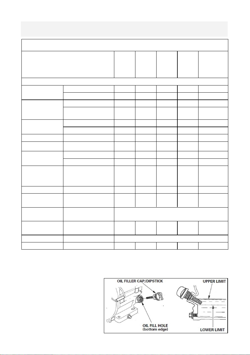
Check oil level daily as shown
above, running the engine
with a low oil level can cause
engine damage.
Refill with Engine Oil type —
SAE 10W30
• * Internal vent carburettor with dual element type only.
• ** Replace paper element type only.
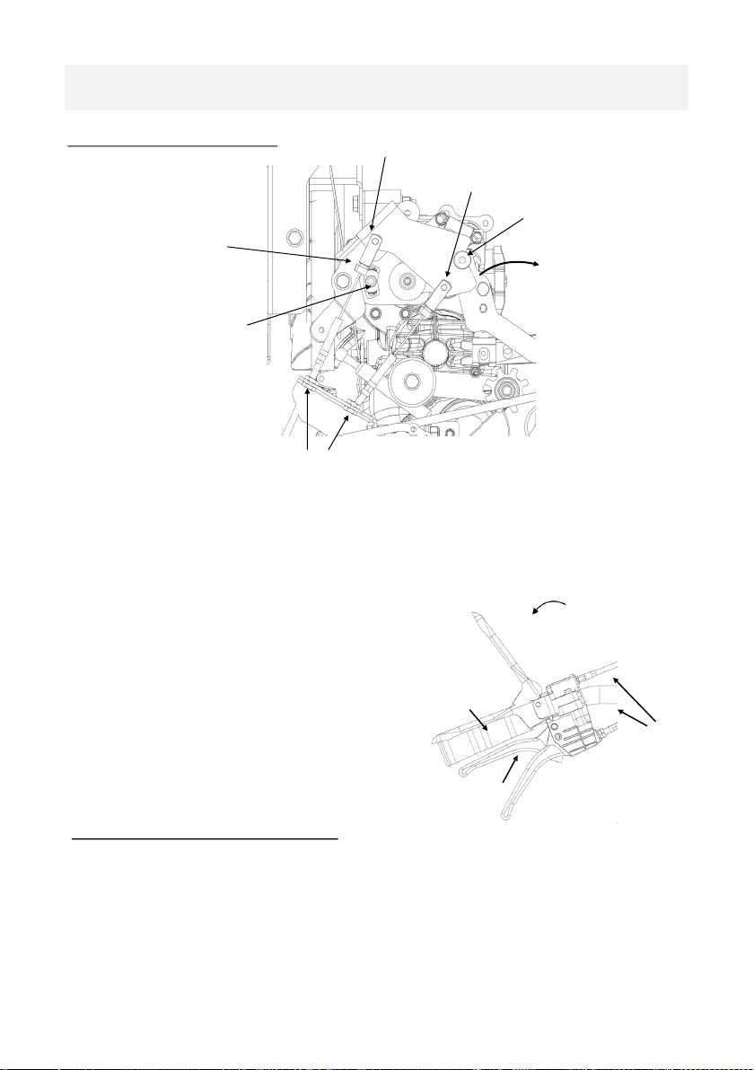
FORWARD CONTROL CABLE
REARWARD CONTROL CABLE
DIRECTION SAFETY
PIN (SHOWN IN
LOCKED POSITION)
CABLE ADJUSTMENT NUTS
PUMP
NEUTRAL
SETTING
DEPRESS
DEADMAN LEVER
TO DISENGAGE PIN
PUMP
DIRECTION
BRACKET
PUMP CONTROL SETTINGS
1: Adjust Deadman lever cable tension if required, see engage angle. Adjust cable
adjustment nuts. With Deadman lever in fully pressed position ensure the direction
safety pin is clear of control plate (see above)
2: Adjust forward/reverse direction levers cable tension if
required, ensure 3mm - 5mm gap when fully
pressed. Adjust cable adjustment nuts.
3: Ensure that with forward lever fully pressed
the pump direction bracket turns
15 degree forward direction 75 rpm @ wheels
4: Ensure that with rearward lever fully
pressed the pump direction bracket turns
5. degree rearward direction 30 rpm @
wheels
PUMP NEUTRAL SETTING
Adjust pump neutral setting if required if machine creeps forwards/backwards when
in neutral,
disconnect forward and rearward control cables
fully press Deadman lever to disengage the direction safety pin
loosen pump neutral setting screw
adjust angle of pump control bracket by rotating forward/backward until no creep
re tighten pump neutral setting screw when wheel rotation is 0 rpm
CABLE
ADJUSTMENT
NUTS
DEADMAN LEVER
10-20 degree
DEADMAN
LEVER
FULLY
PRESSED
DIRECTION
LEVERS
SERVICE & MAINTENANCE - PETROL
Page 13

QUADRO TOP FRAME ASSEMBLY—PARTS LIST
ITEM
NO. PART N0 DESCRIPTION QTY
1 102-03600 FRAME WA RIGID 1
2 101-99914 PRESSING TIP HANDLE 1
3 102-99939 SPACER TIP LEVER 1
4 101-99945 ENGINE COVER 1
5 72-0200 MOULDING TIP HANDLE 1
6 75-01500 CABLE ASSY FWD and REV 2
7 75-02300 CABLE ASSY DEADMAN 1
8 75-00900 CABLE SKIP RELEASE 1
9 74-1022 HANDLE GRIP 2
10 7-10130 COACHBOLT M10 X 30 1
11 74-1023 HINGE 50x50x6 2
12 4-1005 WASHER FLAT M10 FORM A BZP 1
13 8-10006 NUT M10 NYLOC 1
14 7-6056 M6 X 15 BUTTON HD CAP 4
15 4-6001 WASHER M6 FORM A BZP 8
16 7-6007 SCREW - 6 X 15 CSK SCREW BZP 4
17 4-6018 WASHER M6 X 20 X1.2 BZP 4
18 8-6007 NUT M6 NYLOC 12
19 102-99929 TUBE HANDLE 2
20 7-6030-0 M6 X 30 CAP SCREW BZP 4
Page 14

QUADRO TOP FRAME ASSEMBLY—PARTS LIST
Page 15

QUADRO FRONT ASSEMBLY—PARTS LIST
ITEM NO PART NUMBER DESCRIPTION QTY.
1 60-6509LHF WHEEL ASSY 16X6.50X8 LHS FLOAT 2
2 60-6509RHF WHEEL ASSY 16X6.5X8 RHS FLOAT 2
3 100-00500 SKIP 300 W.A. 1
3a 100-00500GL SKIP 300 W.A. GALVANISED 1
4 100-01100 SKIP 450 W.A. 1
4a 100-01100GL SKIP 450 W.A. GALVANISED 1
5 101-02100 FRAME SKIP CARRIER W.A 1
6 102-03300 CHASSIS W.A. 1
7 102-99949 FRONT COVER 1
8 102-99950 TOP COVER 1
9 101-99929 PRESSING TIP RETAINER 2
10 102-03500 REAR AXLE W.A. 1
11 6-1300 DIFFERENTIAL AXLE 1
12 104-99925 GEAR 22T 1
13 102-99921 PRESSING BEARING FRONT 1
14 53-0110 BEARING BALL 25 bore mounted 1
15 53-0110 BEARING BALL 25 bore mounted 1
16 53-0120 BEARING BALL 19.05 bore mounted 2
17 102-03100 WHEEL HUB 2
18 102-99955 COVER FRONT PULLEY 1
19 102-99951 LATCH SKIP 1
20 102-03400 CHANNEL W.A. 1
21 4-1201 WASHER M12 FORM C BZP 1
22 9-10034 SHOULDER BOLT M10 X 16 1
23 102-99956 PIN SKIP LATCH 1
24 7-8080 M8X20 SERRATED HD SCREW 1
25 102-99954 COVER PLATE REAR AXLE 1
Page 16

QUADRO FRONT ASSEMBLY—PARTS LIST
ITEM NO PART NUMBER DESCRIPTION QTY.
26 102-99953 REAR COVER 1
27 6-0006 BANJO BOLT FITTING 1
28 6-0007 BANJO FITTING 1
29 21-2110 CHAIN 5/8" FRONT 1
30 21-2120 CHAIN 5/8" REAR 1
31 102-99958 PRESSING REAR AXLE COVER 1
32 102-99959 PRESSING REAR AXLE ADJUSTER 1
Page 17

QUADRO REAR ASSEMBLY —PARTS LIST
ITEM
NO. PART NO DESCRIPTION QTY.
1 6-2000 TRANSMISSION UNIT 1
2 101-03700 SHAFT OUTPUT DRIVE WA 1
3 102-03200 BRACKET BASE RIGID WA 1
4 8-19001 UNF 3/4" NUT 1
5 20-1600 HONDA GX160 1 300 model
6 20-2000 HONDA GX200 1 450 model
7 101-99956 PRESSING ENGINE DECK 1
8 101-99926 PRESSING FOOT BRKT HONDA 1
9 101-99927 PRESSING DRAIN BRKT HONDA 1
10 21-3040 DRIVE PULLEY 1
11 21-0500 A V MOUNT 30x15xM8 4
12 102-99940 BOSS TENSIONER SUPPORT 8
13 4-8006 WASHER M8 FORM A BZP 8
14 8-8008 NUT M8 NYLOC BZP 8
15 102-99952 COVER LOWER LUG 1
16 6-0004 HOSE 10MM REINFORCED CLEAR 1
17 6-2001 EXPANSION TANK 71328 1
18 2-1010 SPRING EXT 1
19 101-99947 BRACKET LEVER DIRECTION 1
20 101-99948 PLATE BRAKE LOCK 1
21 2-1300 DAMPENER STRUT 1
22 102-99957 BRACKET DAMPENER 1
23 21-3080 BELT - AX24 1
Page 18

QUADRO REAR ASSEMBLY —PARTS LIST
Page 19

LOG POLES X 2 ATTACHMENT FOR TRUXTA (OPTT13-DIO)
1 73-1100 HOLDER STOP 2
2 73-1200 TUBE STOP 2
3 72-0400 MOULDING HUB COVER 2
4 4-1005 WASHER FLAT M10 FORM A BZP 8
5 8-10006 NUT M10 NYLOC 4
6 7-10005 SCREW SET M10 X 25 BZP 4
GREEDY BOARD ATTACHMENT (OPTT15-DIO)
1 73-1601 GREEDY BOARD SIDE LH 1
2 73-1602 GREEDY BOARD SIDE RH 1
3 73-1603 GREEDY BOARD REAR 1
4 7-6060 SCREW M6 X 14 SER HD BZP 10
5 4-6001 WASHER M6 FORM A BZP 10
6 8-6007 NUT M6 NYLOC 10
SKIP CONTROL HANDLE ATTACHMENT (OPTT16-DIO)
1 73-1700 BRACKET SKIP TIPPING 1
2 73-1703 HANDLE SKIP TIPPING 1
3 74-1022 HANDLE GRIP 1
4 3-0096 ROLL PIN 6 X 35 1
5 3-1018 CLIP LYNCH PIN 1
6 7-6060 SCREW M6 X 14 SER HD BZP 2
7 4-6001 WASHER M6 FORM A BZP 2
8 8-6007 NUT M6 NYLOC 2
Page 20
QUADRO ATTACHMENTS - PARTS LIST
FLATBED Q300 - OPTT17-DIO / FLATBED Q450 - OPTT18-DIO
ITEM NO. PART NO DESCRIPTION QTY.
1 73-0120 FLAT BED BOARD 450 2
73-0112 FLAT BED BOARD 300 2
2 7-10035 SCREW M10 X 35 BZP CSK 8
3 4-1005 WASHER FLAT M10 FORM A BZP 12
4 8-10006 NUT M10 NYLOC 12
5 73-2000 QUADRO FLAT BED BASE W.A. 1
6 7-10004 SCREW SET M10 X 20 BZP 4
7 73-1900 QUADRO FLATBED BACK W.A. 1
This manual suits for next models
1
Table of contents
Other Truxta Utility Vehicle manuals


