Trylon COUGAR Guide

IS0
9001
:2000
Registered
INSTALLATIONDRAWINGS
&
INSTRUCTIONS
*
[CDN
VERSION]
Revision date:
May,
2006
/
*
include
with
complete
Kits
I
Fall Protection System
For Ladder Installations

COUGAR INSTALLATION DETAILS FOR CUSTOM TOWERS
[CAN]
START
BOTTOM
RAIL
APPROX~MATELY
3
FEET
FROM
BOTTOM OF LADDER OR BASE STARTING POSITION. LOCATE
RAlL AT CENTER OF LADDER OR CLIMBWAY TO ALLOW
BALANCED FOOT PLACEMENT.
ATTACH THE FIRST CLAMP ONE FOOT FROM ME LOWER
END OF THE BOTTOM RAIL. CLAMP EVERY
4'
TO
5'
AS RUNGS
PERMIT. TOP CLAMP SHOULD BE ON TOP RUNG OF LADDER.
RAlL CAN SAFELY EXTEND MAX.
1.5
FEET ABOVE LADDER
TOP
TO
PERMIT SAFE ARRIVAL AT LADDER TOP. FOR BEST
RESULTS, PLACE CLAMP BOLTS IN CONTINUOUS T-SLOTS
AND FINGER TIGHTEN AT APPROXIMATE LOCATIONS BEFORE
RAISING RAlL SECTIONS INTO PLACE. PUT SPLICE SECTIONS
RAlL TOPS AND TIGHTEN TO ALLOW POSITIVE JOINING OF
RAILS. RAISE AND SECURE THE FIRST RAlL BEFORE
CONTINUING WlTH INTERMEDIATE RAILS. LEAVE 1/16" OPEN
AT EACH JOINT FOR EXPANSION AND CONTRACTION. INSTALL
SPACING TYPICAL TOP RAIL WITH BOLT STOP (3/8' X
2-1/2")
THROUGH
TOP HOLE. THE
318"
BOLTS SUPPLIED ARE SUITABLE FOR
MOST APPLICATIONS.
IMPORTANT NOTE: LADDER TYPE, RUNG SIZE, RUNG
SPACING AND ALL INFORMATION PERTINENT TO THE
INSTALLATION SHOUU) BE GIVEN WHEN ORDERING EACH
KIT. INSTALLATION RECOMMENDATIONS AND SPECIAL
BRACKETS FOR NON-TYPICAL INSTALLATIONS AVAILABLE
REGULAR RAIL BY CONTACTING TRYLON TSF.
TO CLIMB: SLIDE TROLLEY ONTO RAIL. ATTACH SAFETY
HARNESS SNUGLY AROUND WAIST WITH
'0'
RING AT FRONT.
REFER TO MANUFACTURERS INSTRUCTIONS FOR PROPER
BODY FIT ON THE HARNESS. ATTACH TROLLEY SNAP
TO 'D' RING ON HARNESS. LEAN SLIGHTLY AWAY FROM RAlL
TO DISENGAGE PAWL AN0 CLIMB OR DESCEND IN LIKE
MANNER. RELEASING TENSION AUTOMATICALLY ENGAGES
LOCK.
12"f
TO
TYP.
ATTACHMENT NOTES AND DETAILS
ATTACHMENT 3/8"
x
2-1/2"
I
f
BOLT STOP
STAR;
RAIL
Sm
APPROX. 3'-0" FROM FACE VIEW
1.5'
MAX ABOVE TOP RAIL
I
THROUGH LADDER PLATFORM R GRADE OF LADDER TOP CLAMP
I
(LENGTH
TO
SUIT)
TYP,
INSTALLATION DETAIL
FOR
LADDERS
*
BACKING 3/8"0 BOLT
(FULL THREAD)
RAlL
STANDARD RAlL ATTACHMENT
NOTES:
1)
CONFORMS TO STANDARDS:
CSA 2259.2.1
-98
(NOV 16/02 AMENDMENT)
PLEASE NOTE: C.S.A. CERTIFICATION IS VALID ONLY IF THE
SYSTEM IS INSTALLED USING MANUFACTURERS
COMPONENTS AND IN ACCORDANCE NTH
THE MANUFACTURERS INSTRUCTIONS
1/16"
EXPANSION
GAP
\INTERNAL
SPLICE
BAR
AT ALL SPLICES
-k
EplN
REGULAR RAlL
(20' Lg.)
3/8"0 BOLT
(FULL
THREAD)
COUGAR TROLLE
TROLLEY LEVER
KARABINER
t
13'
APPROX.
(TO GROUND OR PLATFORM)
BODY
fi
TRYLON
TIF
21
?O;THFIELO
DRIVE,
PO
BOX 186, ELMIRA, ONTARIO. N3B 226
TFI
.1.519\ 669-5431
FAX.(!i19)
669-8917

0
TRY
LON
TIF
21
Southfield Drive, PO Box
186,
Elmira, Ontario,
N3B
226
-
Tel:
(519) 669-5421
-
Fax:
(519)669-8912
SAFETY RAIL SYSTEM INSTRUCTIONS
Important
-
Read and UnderstandThis Document Before Installationor Useof Svstem!
Warning
Manufacturer's instructions must be followed regarding proper system use, maintenanceand installation.
Alternations or misuse of product or failureto follow instructionsmay result in serious injury ordeath.
All safetv rail systems and components are to be used under the safetv standards in place in the iurisdiction in which
you are working. These instructions are not meant to supersede anv local or federal safetv standards.
Any Safety Trolley, which has seen fall arresting service, should not beused after such service and returned
tothe manufacture for immediate inspection. Aswell the whole svstem: trolley, rail and all accessories will
need to be inspected and replaced at once. Until a full replacement ofthe system
is
implemented you should
not ascend ordescend
on
a
system that has incurred usage of
a
fall.
Use
-
Trylon's Safety Trolley
&
Rail system is intended to arrest personnel (not material) should they (the individual) slip or
fall while climbing.
Ensure the anchorage system can support a minimum load of
2500
pounds. Certification is applicable to the device
only. Neither the manufacturer nor CSA has investigated the anchorage system. The Safety Rail Trolley is designed to
work onTrylon's Safety Rail Systems only.
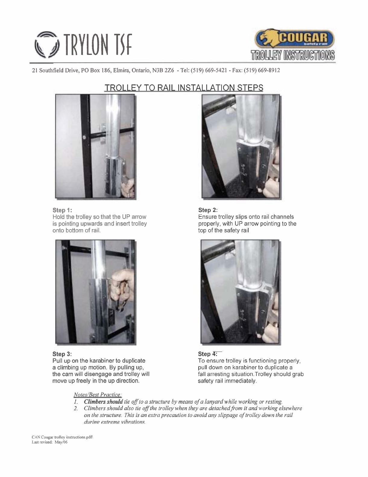
Climbers should always tie off to a structure by means of a lanyard while working or resting. When detaching from the
trolley to work elsewhere on the structure, as a best practice, climbers should also tie off their trolley to avoid the
unlikely event ofthe trolley 'slipping' down the rail during extreme vibrations.
Trylon Fall Protection systemsare not intended to be used asa life line or work position device while working.
Body harnesses supplied with the Fall Protection system may require the use of D-Rings or carabiners to provide a safe
and comfortable fit for the attachment on climber's harness. Length of attachment and clothing should not impede the
locking mechanism on the slider.
Do not exceed
6
inches of distance between slider and attachment point.
Training
Climbers should fully familiarize themselves with the operation of the system before ascendingthe structure or tower.
As well they should insure that the body harness is properly equipped sb
it
does not interfere with arresting features of
the fall protection system. Make certain all applicable hazards are addressed properly to provide climber safety.
Hazardous power lines, antenna radiation, physical obstructions, icing, frost, in addition to climber's knowledge,
ability and health. The Safety Trolley and Rail System is designed for use by one climber at a time.
Inspection
The Safety Rail Trolley system is designed to function as an integrated system and the use of non-compatible materials
is not recommended and may impair performance.

(cont'd)
SAFETYRAIL SYSTEM INSTRUCTIONS
--
-
A visual inspection of the Trolley is required before each use. Some of the main inspection points include ensuringthat
the compression spring is in place and not missing, ensure that all four rollers (wheels) are in place and secure, turning
the unit over to ensurethat the SafetyLockTMorientation lock-out device moves freely. Always check Trolley before
ascending to ensure it runs free and locksproperly onto the rail.
Detailed inspections should be conducted on a regularly scheduled basis as determined by user; a minimum
(2)
detailed inspections per year. All worn Trolley parts should be returned to the manufacturer for repair or replacement.
If
a
unit is unsatisfactory due not attempt to climb with
it
and remove it from service immediately and notify
supervisor.
Care and Maintenance
All trolleys should be stored in a clean, dry areawith limited exposure tothe following:
1)
sunlight
2)
excessive heat
3)
harmful fumes
4)
corrosive chemicals or conditions
The trolley can be cleaned by dipping it in a mild soap and water solution. Donot use harsh detergents or chemicals or
pressure washers. After cleaning, the unit should be rinsed in clear water and allowed to air dry naturally. After
washing, hardware should be inspected. No lubrication is necessary.
CAN
Cougar rail install manual.pdf\
Last revised:
May!Ob

TRYlON
TIC
21
SouthfieldDrive,
PO
Box
186,
Elmira,
Ontario,
N3B
226
-
Tel:(519) 669-5421
-
Fax:
(519) 669-8912
TROLLEY TO RAIL INSTALLATION STEPS
Step
1
:
Holdthe trolley sothat the UP arrow
is pointing upwards and inserttrolley
onto bottom of rail.
Step
2:
Ensuretrolley slips onto rail channels
properly,with
UP
arrow pointing to the
top of the safety rail
Step
3:
Pull up on the karabiner to duplicate
a climbing up motion.
By
pulling up,
the cam will disengage and trolley will
move upfreely in the up direction.
Step
4:
To ensure trolley is functioning properly,
pull down on karabiner to duplicate a
fall arresting situation.Trolley should grab
safety rail immediately.
Notes/Best Practice:
I.
Climbersshould tie off toa structure
by
means of a lanyardwhile working or resting.
2.
Climbersshould also tie off the trolleywhen they are detachedfiom it and working elsewhere
on thestructure. Thisisan extraprecaution toavoid anyslippage of trolleydown the rail
durin~extreme vibrations.
CAN
Cougar
trolley
instructions.pdA
Last
revised:
May106
Popular Protection Device manuals by other brands

Epcos
Epcos CeraDiodes manual

INPRO
INPRO 1100/G2 installation instructions

ZDS
ZDS DRP Version 2.0-BLUE Installation & operating instructions

Intermatic
Intermatic PG4000 Installation instructions and operating manual

WATANABE
WATANABE WSP-IS instruction manual

Tapeswitch
Tapeswitch PRSU/2 Operating instructions manual