tryten Nova Pro User manual
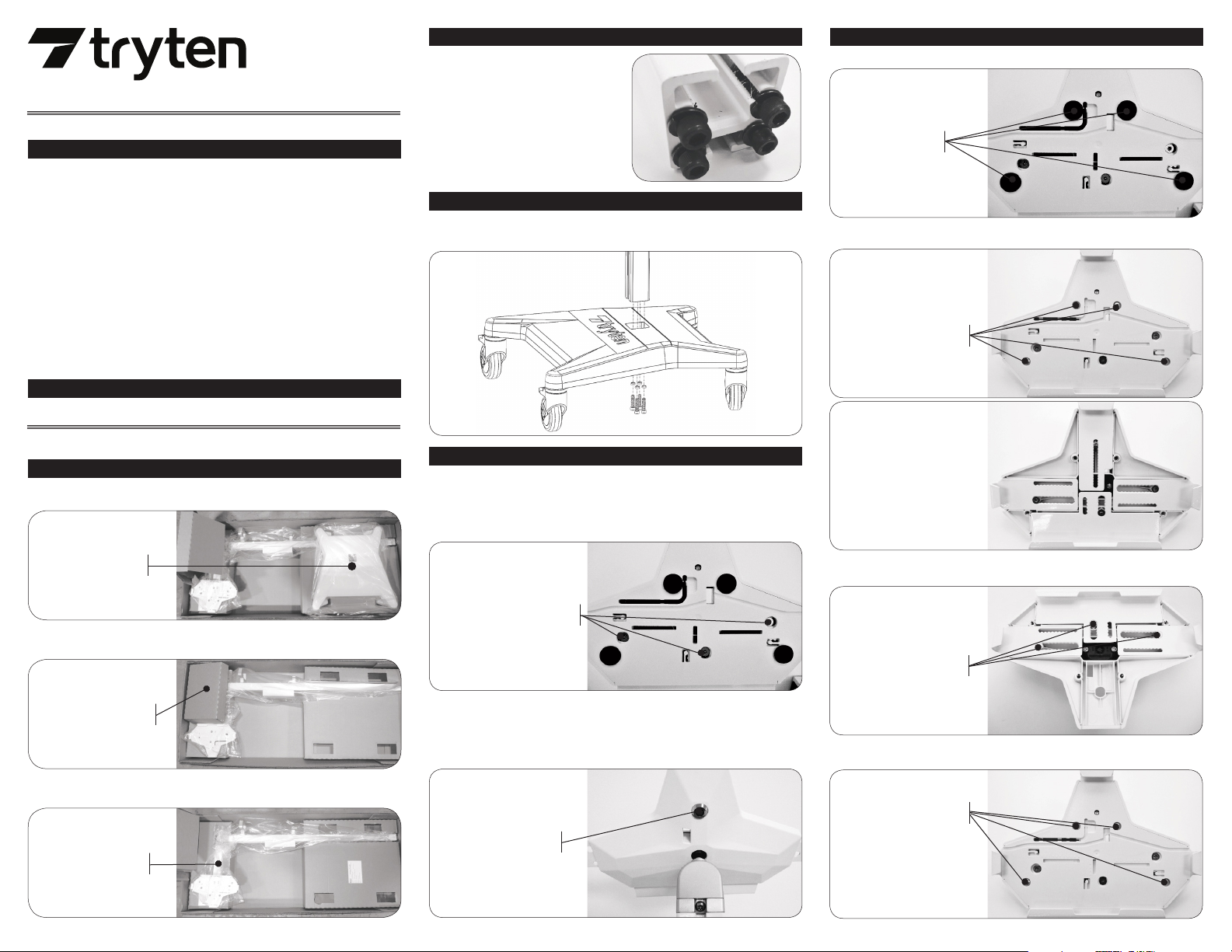
Open shipping box and remove base assembly.
•
Remove 4 screws and split washers from Pole
assembly using the 3/16-inch hex L key from
the hardware pack.
Unlock the top slider using the set of keys from the hardware pack.
Remove the top slider from the OmniTab.
Loosen the 3 screws using the 1/8-inch hex L key from the hardware pack.
Pull sliders to the appropriate size tablet.
Tight back the three adjustment screws.
Slide the tablet into place.
Insert the Top slider and push the locking button.
•
Assemble the Pole assembly to the base using the 4 screws and split washers that came with the
Pole assembly using the 3/16-inch hex L key from the hardware pack.
•
Extract hardware pack.
•
Remove Pole assembly from packaging.
•
BASE ASSEMBLY
HARDWARE PACK
POLE ASSEMBLY
The Universal bracket comes adjusted to t the standard iPad 9.7.
•
•
•
•
•
•
•
ADJUSTMENT SCREWS
LOCK BUTTON
FELT PADS
a) Remove 4 felt pads from Universal bracket.
COVER
HOLDING SCREWS
b) Remove 4 screws holding the cover of the Universal bracket using the 1/8-inch hex L key from
the hardware pack.
Remove cover and the 3 screws
holding the sliders using the 1/8-inch
hex L key from the hardware pack.
SLIDERS
HOLDING SCREWS
d) Remove for sliders and replace with the set of sliders from hardware pack.
e) Install the 3 screws holding the sliders using the 1/8-inch hex L key from the hardware pack.
f) Put back the cover and install the 4 screws removed at step b) using the 1/8-inch hex L key from
the hardware pack.
COVER
HOLDING SCREWS
c)
Apply the set of felt pads supplied
in the hardware pack on top of the
screws.
Adjust sliders and install tablet
following the instructions from
Step 4.
g)
h)
1. OPEN THE SHIPPING BOX
2. PREP THE POLE ASSEMBLY
4. ADJUST UNIVERSAL BRACKET TO FIT THE SIZE OF THE TABLET
ASSEMBLY INSTRUCTIONS
3. ASSEMBLE THE POLE ASSEMBLY
5. WHEN A TABLET HAS A CASE, INSTALL 2ND SET OF SLIDERS
Nova Pro Pole Assembly Hardware Pack
• 1 of 3/32 Hex Key
• 1 of 5/16”-18 x 1 1/4”ange bolt
• 1 of 10-32 x 7/8”set screw
Nova Pro Bracket Assembly Hardware Pack
• 1 of ¼”-20 x 7/16”Toplock nut
• 2 of 10-32 x 3/8”Long at-head socket cap screws
• 1 of 1/8”Hex Drive Key
• 1 thick swivel head washer
• 1 thin swivel head washer
• 1 Set of 2 keys
Nova Pro Wire Basket Hardware Pack
• 2 of 10-32 x 3/8”long at-head socket cap screws
• 1 – ¼ turn ¼-20 Z-Nut
• 1 screw for 80/20 nut, socket head cap screw ¼”-20 x 1.5”long
ASSEMBLY KIT
• 7/16”Socket, ½” Socket
Nova Pro HARDWARE PACKS
ADDITIONAL TOOLS REQUIRED
NOVA PRO Modular Medical Tablet Cart
ASSEMBLY INSTRUCTIONS - continued
First, remove the lower channel cover. Use an Allen key at the base of the channel cover to pry it
o of the pole.
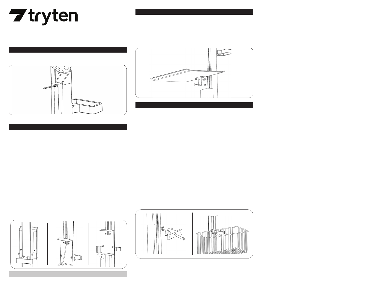
In the basket hardware kit you will nd a ¼” screw and a T-nut. Insert screw into basket bracket
and thread on the T-nut but do not tighten. Make sure the T-nut is in the proper orientation so it
ts snugly inside the channel of the pole.
Adjust height of mounting bracket now to where you want it.
Tighten the mounting bracket into the pole when happy with the placement using the 3/16 Allen
key.
Place the top rim of the basket on the top of the mounting bracket.
Center the basket to the middle of the pole.
Attach the basket using the clamp which ts over the basket on top of the mounting bracket. The
clamp is designed to t over the basket grooves and attaches to the mounting bracket, holding
the basket rmly in place.
Install and tighten the 2 screws provided with your hardware kit using the 1/8 Allen key.
Once you have the basket permanently in place, you can resize the lower channel cover strip.
Measure the height of the remaining channel to size cover, leaving at least ¼“ of space at the top
for the Lightning cable. You might need to cut two strips, depending on where you placed the
storage basket. One strip above the storage basket and one strip below. Cut each strip to size and
push back into place under and over the basket accessory.
•
•
•
•
•
•
•
•
•
The wire basket storage accessory comes in 3 parts – the basket itself, the mounting bracket and
clamp to attach to the pole. The storage basket gets installed just below the power box on the lower
part of the pole.
Insert one of the smaller Allen keys in behind the top of the channel cover to pull out of the pole. You
need to reinstall these covers back into place after power cords are in place.
To install the power cord, charging cable and power adapter, you rst must open the Power Box,
located in the center of the pole.Turn the unit around to the back to locate 2 screws at the back of
the Power Box. Using your 3/32 Allen Key, loosen and remove the 2 screws located on the back of
the Power Box. Keep screws in a safe place.
The Power Box cover should now easily slide o by lifting it up or down.
Turn the unit back around so the front of Power Box is facing you.
Slide the small end of the Apple Lightning Connector cable into the small hole of the Power Box,
and up the pole. It should easily t. Leave the other end of the Lightning cable inside the power
box to connect later.
Plug your tablet’s power adapter (inside the Power Box) into the 9’ Green Dot Certied Hospital
Grade power extension cable.
The power extension cable can now t inside the bottom slot of the Power Box to store cables
rmly inside the Power Box.
Slide Power Box cover back into place and screw the Power Box back into place using the 2 screws
and the 3/32 Allen Key. Make sure both screws are lined up properly before tightening completely.
Reinstall top 2 channel covers to protect your charging cable that runs up inside the pole. Leave
room at the top for the cable to poke through in both channel covers. Make sure that the cable
has enough exibility for the unit to bend. Do not thread cable too tightly inside the unit. There
should be ample cable slack along the pole.
Connect your tablet’s charging cable to your tablet.
•
•
•
•
•
•
•
•
•
6. REMOVE CHANNEL COVER STRIPS
7. INSTALL THE POWER CORD
NOTE: Channel cover strips will need to be adjusted if you purchase accessories.
9. INSTALL THE WIRE STORAGE BASKET ACCESSORY
STORING THE POWER CORD
When the cart is not in use, or tablet is not being charged, the extension cord should be wrapped
and stored on the unit. Wrap the cable rmly around the upper handle and lower handle cord wraps
located on the back of the unit pole.
Remove the channel cover strip. Channel cover will need to be resized after installation of tray.
The tray comes with 2 screws and 2 Z-nuts.
Loosen Z-nuts from screws but do not remove; align Z-nuts so they slide into pole channel.
Use 5/32” allen key to tighten screws. Before tightening completely, adjust height of tray to
desired position and then tighten screws.
The channel strip can be resized to suit the Work Surface location.
•
•
•
•
•
8. INSTALL THE WORK SURFACE ACCESSORY TRAY
NOVA PRO Modular Medical Tablet Cart
Other manuals for Nova Pro
1


