Brinly RPC-10BH-A User manual

11020337EN-A
Call Customer Service, Toll-Free: 877-728-8224
Important: This manual contains information for the safety
of persons and property. Read it carefully before
assembly and operation of the equipment!
Visit us on the web!
www.brinly.com
• Assembly
• Installation
• Operation
• Repair Parts
ROGER POLY CART, 10 CUBIC FOOT
MODEL:
RPC-10BH-A
This utility cart is designed
for use with lawn tractors and
lawn and garden tractors.
English Manual
OWNER'S MANUAL
English, Spanish &
French Manual

21020337EN-A
==================================================================================================
English Manual
INTRODUCTION AND SAFETY
CUSTOMER RESPONSIBILITIES
- Please read & retain this manual. The instructions will enable to assemble and maintain your product properly.
- Please carefully read and observe the SAFETY SECTION of this manual.
- Follow a regular schedule in maintaining and caring for your Brinly-Hardy product.
CONGRATULATIONS on your new Brinly-Hardy purchase! This accessory has been designed, engineered and manufactured
to give you the best possible dependability and performance.
Should you experience any problem you cannot easily remedy, please do not hesitate to contact our knowledgeable customer
service department toll-free at 1-877-728-8224. We have competent, well trained technicians to help you with the assembly
and use of your product.
TABLE OF CONTENTS
Introduction, Safety and
Required Tools ............... 2 - 4
Parts ....................... 5 - 9
Assembly .................. 10 - 20
USE AND CARE
Specifications ................. 21
Operation ................. 21 - 24
Adding Side-Stakes ......... 25 - 27
Service ...................... 27
Accessories .................. 27
Warranty ..................... 28
TOOLS REQUIRED
FOR ASSEMBLY:
=============================
• 1/2” Wrench (x2)
• 9/16” Wrench (x2)
• Flat Tip Screw Driver
• Pliers
• Gloves The safety labels shown in this section are placed in important
areas on your product to draw attention to potential safety hazards.
On your product safety labels, the words DANGER, WARNING and
CAUTION are used with the safety-alert symbol. DANGER identifies
the most serious hazards.
The operator’s manual also explains any potential safety hazards
whenever necessary in special safety messages that are identied with
the word, CAUTION, and the safety-alert symbol.
This symbol will help to point out important
safety precautions throughout this manual. It means:
ATTENTION! BECOME ALERT! YOUR SAFETY
IS INVOLVED.
RECORD PURCHASE INFORMATION
Record your purchase information in the spaces provided below:
DATE OF
PURCHASE ��������������������������������������������������������
COMPANY
NAME ��������������������������������������������������������
COMPANY
PHONE ��������������������������������������������������������
SERIAL
NUMBER ��������������������������������������������������������
SAFETY LABELS

31020337EN-A
==================================================================================================
English Manual
SAFETY
GENERAL SAFETY NOTES ( Operation )
• Ensure the combined weight of the towing vehicle (tow vehicle
weight + operator weight) is greater than the maximum towed
weight of attachment (empty attachment weight + weight of
load).
• Do not exceed maximum towing capacity of towing vehicle.
• Do not exceed the maximum drawbar pull rating of the towing
vehicle. Drawbar pull is the horizontal force required to pull the
attachment (including weight of load).
• Only tow this product in the vehicle’s tow mode/speed setting
or less than 5 mph. Do not exceed 5 mph.
• Towing speed should always be slow enough to maintain
control. Travel slowly and use caution when traveling over
rough terrain. Avoid holes, rocks and roots.
• Slow down before you turn and do not turn sharply.
• Use wide turning angles to ensure the attachment follows the
path of the towing vehicle.
Cautionshouldbetakenwhentowingand/orusinganyattachment. Thisattachmentcombinedwiththeweightdistribution,
turning radius, and speed of towing vehicle can result in severe injury or death to operator, damage to towing vehicle,
and/or attachment if not used properly. Follow all towing safety precautions noted in the towing vehicle owner’s manual,
including the following precautions:
• Do not use attachment on steep slopes. A heavy load could
cause loss of control or overturn attachment and towing vehicle.
Additional weights may need to be added to your vehicle;
check with towing vehicle manufacturer for recommendations.
• Reduce towed weight when operating on slopes.
• Keep all movement on slopes slow and gradual. Do not make
sudden changes in speed, directions, or turning.
• If you start and stop suddenly on hills, you may lose steering
control or the towing vehicle may tip.
• Do not start or stop suddenly when going uphill or downhill.
Avoid uphill starts.
• Slow down and use extra care on hillsides. Turf conditions
can aect vehicle stability. Use extreme caution while
operating near drop-os.
• Do not drive close to creeks, ditches and public highways.
• Watch out for trac when crossing near roadways.
WARNING
AVOID INJURY FROM EXPLOSION
• Do not place gas container in cart when lling
RIDERS CAN FALL OFF AND BE KILLED
• No riders in cart
B-7084

41020337EN-A
==================================================================================================
English Manual
STOP
Installation Questions?
Missing Parts? Replacement Parts?
DON’T GO BACK TO
THE STORE!
Please call our Customer Service
Department, Toll Free: 877-728-8224
or customerservice@brinly.com
• Use care when loading or unloading the vehicle
into a trailer or truck.
• The attachment can obstruct the view to the rear. Use extra
care when operating in reverse.
• When reversing, carefully back-up straight to avoid jackkning.
Do not allow towing vehicle wheels to contact attachment draw
bar. Damage could result.
• Stop on level ground, disengage drives, set the parking brake,
and shut o engine before leaving the operator’s position for
any reason including emptying the attachment.
• Use this attachment for intended purpose only.
• This attachment is intended for use in lawn care and home
applications. Do not tow behind a vehicle on a highway or in
any high speed applications.
• Do not tow at speeds higher than the maximum
recommended towing speed.
• Do not tow this product behind a motor vehicle such
as a car or truck.
• Always wear substantial footwear. Do not wear loose tting
clothing that can get caught in moving parts.
• Keep your eyes and mind on your towing vehicle, attachment
and area being covered. Do not let other interests distract you.
• Stay alert for holes and other hidden hazards in the terrain
• Keep the towing vehicle and attachment in good operating
condition and keep safety devices in place.
• The towing vehicle and attachment should be stopped and
inspected for damage after striking a foreign object. Any
damage should be repaired before restarting and operating the
equipment.
• Keep all parts in good condition and properly installed. Fix
damaged parts immediately. Replace worn or broken parts.
Replace all worn or damaged safety and instruction decals.
Keep all nuts, bolts and screws tight.
• Do not modify the attachment or safety devices. Unauthorized
modications to the towing vehicle or attachment may impair its
function, safety and void the warranty.
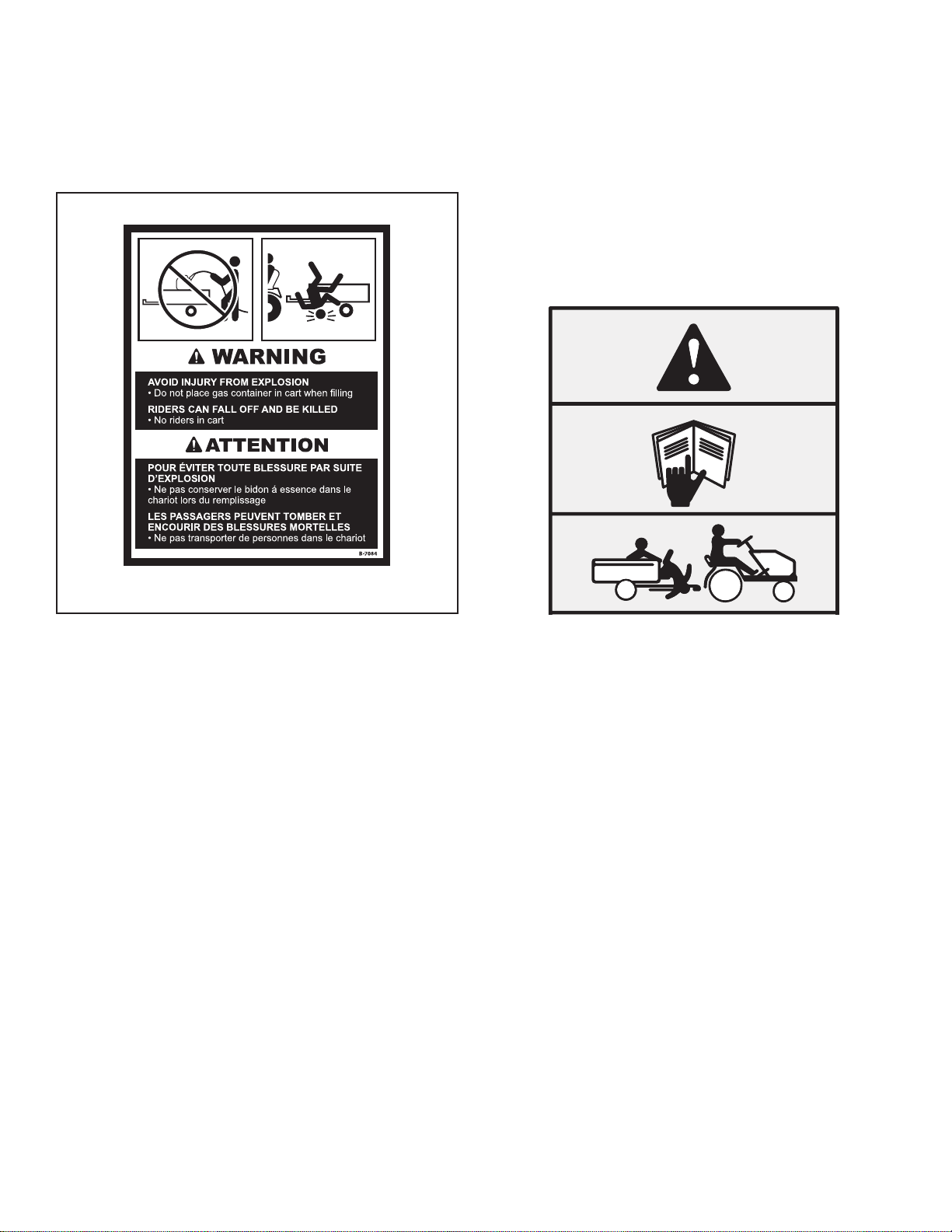
KEEP RIDERS OFF TOWED
ATTACHMENT AND TOWING VEHICLE
• Do not carry passengers.
• Do not let anyone, especially children, ride in/on this
attachment, the towing vehicle or hitch bracket.
• Riders are subject to injury such as being struck by foreign
object and/or being thrown o during sudden starts, stops
and turns.
• Riders may also obstruct the operator’s view resulting in this
attachment being operated in an unsafe manner.
TOWING VEHICLE AND TOWING SAFELY
• Know your towing vehicle controls and how to stop safely.
READ YOUR TOWING VEHICLE OWNER’S MANUAL before
operating.
• Check the towing vehicle brake action before you operate.
Adjust or service brakes as necessary.
• Stopping distance increases with speed and weight of towed
load. Travel slowly and allow extra time and distance to stop.
• Use only approved hitches. Tow this attachment only with a
towing vehicle that has a hitch designed for towing. Do not
connect this attachment except at the approved hitch point.
• Follow the tow vehicle manufacture’s recommendations for
weight limits for towed equipment and towing on slopes. Use
counterweights or wheel weights as described in the towing
vehicle operator’s manual.
• Do not shift to neutral and coast downhill.
• Do not allow children to operate the towing vehicle. Do not
allow adults to operate the towing vehicle without proper
instruction or without having read the owner’s manual.
PROTECT THOSE AROUND YOU
• Before you operate any feature of this attachment or towing
vehicle, observe your surroundings and look for bystanders.
• Keep children, bystanders and pets at a safe distance away
while operating this or any attachment.
• Use care when reversing. Before you back up, look carefully
behind for bystanders.
POLY CART SPECIFIC SAFETY INSTRUCTIONS
• Do not tow cart with bed raised.
GENERAL SAFETY NOTES ( Operation )
SAFETY

51020337EN-A
==================================================================================================
English Manual
PART LIST
Ref. Part # Description Qty.
1 1020336SER Cart Bed; Poly RPC-10BH-A 1
4 1020374 Draw Bar; Poly Cart 1
6 B-4261 Axle, 3/4" x 34-3/4" 1
7 B-4599-10 Axle Support 1
8 1008575 Wheel; Pneumatic 2
9 1018697-10 Right Pivot Arm 1
10 1018698-10 Left Pivot Arm 1
1019851 INNER PACK #1
2 B-3520-10 Lock Bracket 1
3 1008604 Foot Pedal 1
5 B-3034-10 Clevis 1
N/A Z-1737 Hardware Skin Pack
* illustrated on page 8
1
21 40M1000P - Washer; Lock, 5/16" 12
22 45M1111P - Washer; Flat, 5/16" 10
24 B-5606 - Bushing; Machine 4
25 30M1000P - Nut; Reg Hex, 5/16"-18 12
26 B-1675P - Nut; Hex Lock, 3/8"-16 1
27 B-6299 - Nut; Keps Hex, 3/8-16 2
28 B-6298 - Bolt; Hex Head, 3/8 x 3-3/4 1
29 20M1016P - Screw; Round Head
Machine, 5/16" x 1" 12
30 B-4305 - E-Ring; Retaining, 3/4" 2
31 B-6300 - Spring; Latch 1
32 B-3861 - Pin; Hitch, 1/2" x 2-1/2" 1
33 D-146P - Hairpin Cotter, 1/8" 1
Extra parts in Skin Pack that are not needed:
1007732 - Washer; Nylon 4
R-618 - Washer; Special 2
1020347 INNER PACK #2
11 1018681-10 Rocker Base 1
12 1018687-10 Axle Support Bracket 1
13 1018682-10 Rocker Motion Bracket 1
14 1018881 Rocker Handle 1
15 1018684-10 Rear Pivot Bracket 2
N/A 1020338 Hardware Bag
* illustrated on page 9
1
21 40M1000P - Washer; Lock, 5/16" 6
34 45M1313P - Washer; Flat, 3/8" 2
25 30M1000P - Nut; Reg Hex, 5/16"-18 6
35 B-4786 - Nut; Nylon Lock, 5/16"-18 2
36 B-4820 - Nut; Nylon Lock, 3/8"-16 4
37 11M1016P - Bolt; Carriage, 5/16" x 1" 8
38 2M1220P - Bolt; Hex Head, 3/8" x 1-1/4" 2
39 2M1248P - Bolt; Hex Head, 3/8" x 3" 2
40 1001301 - Spinner Shaft Bushing, 3/8" 2
31 B-6300 - Spring; Latch 1
41 R-1882 - Grip; Flat 1

61020337EN-A
==================================================================================================
English Manual
EXPLODED VIEW (1 of 2)
Ref. Part # Description Qty.
1 1020336SER Cart Bed; Poly RPC-10BH-A 1
4 1020374 Draw Bar; Poly Cart 1
6 B-4261 Axle, 3/4" x 34-3/4" 1
7 B-4599-10 Axle Support 1
8 1008575 Wheel; Pneumatic 2
9 1018697-10 Right Pivot Arm 1
10 1018698-10 Left Pivot Arm 1
1019851 INNER PACK #1 Qty.
2 B-3520-10 Lock Bracket 1
3 1008603 Foot Pedal 1
5 B-3034-10 Clevis, Blk. 1
N/A Z-1737 Hardware Skin Pack
* contents on page 5
* illustrated on page 8
1
1020347 INNER PACK #2
11 1018681-10 Rocker Base 1
12 1018687-10 Axle Support Bracket 1
13 1018682-10 Rocker Motion Bracket 1
14 1018683-10 Rocker Handle 1
15 1018684-10 Rear Pivot Bracket 2
N/A 1020338 Hardware Bag
* contents on page 5
* illustrated on page 9
1
1
21
21
25
25
11
2
13
x2
22
29
x4
22
29
38
36
34
40
31
14
35 40
36
34
38
37
25 21

71020337EN-A
==================================================================================================
English Manual
EXPLODED VIEW (2 of 2)
Ref. Part # Description Qty.
1 1020336SER Cart Bed; Poly RPC-10BH-A 1
4 1020374 Draw Bar; Poly Cart 1
6 B-4261 Axle, 3/4" x 34-3/4" 1
7 B-4599-10 Axle Support 1
8 1008575 Wheel; Pneumatic 2
9 1018697-10 Right Pivot Arm 1
10 1018698-10 Left Pivot Arm 1
1019851 INNER PACK #1 Qty.
2 B-3520-10 Lock Bracket 1
3 1008603 Foot Pedal 1
5 B-3034-10 Clevis, Blk. 1
N/A Z-1737 Hardware Skin Pack
* contents on page 5
* illustrated on page 8
1
1020347 INNER PACK #2
11 1018681-10 Rocker Base 1
12 1018687-10 Axle Support Bracket 1
13 1018682-10 Rocker Motion Bracket 1
14 1018683-10 Rocker Handle 1
15 1018684-10 Rear Pivot Bracket 2
N/A 1020338 Hardware Bag
* contents on page 5
* illustrated on page 9
1
12
7
15
39
3
4
6
8
8
29
33
32
21
25
22 29
36
37
31
26
28
27
+
21 25
7
24
30
+
2521
37
37
37
24
+
21
25
24
30
+
25
21
24
9
10

81020337EN-A
==================================================================================================
English Manual
Contents of this page can be found in: Hardware Skin Pack Z-1737
DO NOT RETURN PRODUCT IF YOU ARE MISSING PARTS.
Please Call: 1 (877) 728-8224
HARDWARE IDENTIFIER
Illustrations on this page
are to scale for faster
identication of hardware
during assembly.
Hitch Pin;
1/2" x 2 1/2" (x1) . . . . . . . . . . . . . . . .
B-3861
32
Nut: Hex Head
5/16” -18 (x12) . . . . . . . . . .
25
30M1000P
Nut: Keps
3/8” (x2) . . . . . . . . . . . . . .
27
B-6299
Nut: Lock
3/8” -16 (x1) . . . . . . . . . . . .
26
B-1675P
Washer: Lock
5/16” (x12) . . . . . . . . . . . . .
21
40M1000P
Washer: Flat
5/16” (x10) . . . . . . . . . . .
45M1111P
22
Bolt: Hex Head
3/8 x 3 3/4” (x1) . . . . . . . . . . . . . . . . .
B-6298
28
29
Hairpin Cotter, 1/8" (x1)
D-146P . . . . . . . . . . . . . . . .
33
Retaining Ring, E
3/4” (x2) . . . . . . . . . . . . . . .
30
B-4305
Spring, Latch (x1)
B-6300
31
. . . . . . . . . . . .
A few extra parts will be leftover that are not used on this model.
( 3/4" Nylon Washer - Qty. 4 ) and ( 3/8" Special Washer - Qty. 2 )
EXTRA PARTS:
Machine
Bushing (x4) . . . . .
B-5606
24
Screw: Round Head
5/16 x 1” (x12) . . . . . . .
20M1016P
Z-1737 Skin Pack
Rd.Hd. Screw 5/16" x 1"
Qty.8
Rd.Hd. Screw 5/16" x 1"
Qty.2
HexNut 5/16"
Qty.8
HexNut 5/16"
Qty.2
Panel1
FlatWasher 5/16"
Qty.8
FlatWasher 5/16"
Qty.2
LockWasher 5/16"
Qty.8
LockWasher 5/16"
Qty.2 OversizeWasher
Qty.2
HexNut 5/16"
Qty.2 LockWasher 5/16"
Qty.2
KepsNut 3/8"
Qty.2
LockNut 3/8"
Qty.1
HexBolt 3/8” x 3-3/4”
Qty.1
LatchSpring
Qty.1
NOTE: USE METAL BUSHINGS ONLY ON 10P CART
USENYLON BUSHINGS ONLY ON 7P CART
Panel4
HitchPin 1/2" x 2-1/2"
Qty.1 HairpinCotter 1/8"
Qty.1
Panel6
Panel5
3/4"Metal Bushing (For 10P Carts ONLY!)
Qty.4
3/4"Nylon Bushing (For 7P Carts ONLY!)
Qty.4
RetainingRing E-type
Qty.2
RevisionL
Panel2
Panel3
NOTE: OVERSIZE WASHERS
USEDON 7P CART ONLY
Rd.Hd. Screw 5/16" x 1"
Qty.2
NOTE: LATCH SPRING USED
ON10P CART ONLY

91020337EN-A
==================================================================================================
English Manual
DO NOT RETURN PRODUCT IF YOU ARE MISSING PARTS.
Please Call: 1 (877) 728-8224
HARDWARE IDENTIFIER
Illustrations on this page
are to scale for faster
identication of hardware
during assembly.
40 Bushing; Hex Head
3/8” x 1/2" (x2). . . . . . . . . . . .
1001301
Bolt; Hex Head
3/8 x 1 1/4” (x2) . . . .
2M1220P
38
31 Spring (x1) . . . . . . . . . . . . . .
B-6300
35 Nut: Nylon Lock
5/16” (x2) . . . . . . . . . . . . . .
B-4786
25 Nut: Hex Head
5/16” (x6) . . . . . . . . . . . . . .
30M1000P
36 Nut: Nylon Lock
3/8” (x4) . . . . . . . . . . . . . .
B-4820
Bolt: Hex Head 3/8 x 3” (x2) . . . . . . . . . . . . . .
2M1248P
39
Grip: Flat
( for Handle )
(x1) . . . . . . . . . . . . . . . . . . . . . . . .
R-1882
41
Exterior circumferences of the washers can
vary. These dimensions are a measurement
of the internal diameter of the washer.
34
Washer: Flat
3/8” (x2) . . . . . . . . . . . . .
45M1313P
21 Washer: Lock
5/16” (x6) . . . . . . . . . . . . . . .
40M1000P
Contents of this page can be found in: Hardware Bag 1020338
Bolt; Carriage
5/16 x 1” (x8) . . . . .
11M1016P
37

10 1020337EN-A
==================================================================================================
English Manual
ASSEMBLY
Assembly Tip
- Illustrations on pages 8-9 are to-scale. For faster identication of
the hardware during assembly, simply lay the hardware on top of these
illustrations.
- This product comes with a skin pack as well as a bag of
hardware. The source of hardware needed (skin pack or bag)
will be marked on each step. NOTE: There will be a few extra
/unnecessary pieces of hardware in the skinpack.
- Scan this QR code or visit our website for
additional info and videos: brinly.com
NOTE: There will be two washers in this hardware panel remaining.
These are unnecessary for this model, please disregard.
x2
Step 1
29
22
25
21
Lock
Bracket
+
Cart
Bed
1
2
Install Lock Bracket
1. Add a 5/16 Flat Washer (22)
to two of the Slotted Head
5/16 Screws (29).
These screws will run
through the bed of the cart (1)
from inside to attach the lock
bracket (2) on the next step.
2. Place the Lock Bracket (2)
on cart as illustrated,
NOTE: Make sure notch on
lock bracket is facing to the
front of the cart.
3. Add two 5/16 in. Lock
Washers (21) as well as two 5/16 in.
Nuts (25). Tighten nuts.
21
21
25
25
22
22
29
29
2
1
Skin Pack Panel 2
91020337ALL-A
==================================================================================================
English Manual
DO NOT RETURN PRODUCT IF YOU ARE MISSING PARTS.
Please Call: 1 (877) 728-8224
HARDWARE IDENTIFIER
Illustrations on this page
are to scale for faster
identication of hardware
during assembly.
40
Bushing; Hex Head
3/8” x 1/2" (x2). . . . . . . . . . .
1001301
Bolt; Carriage
5/16 x 1”
(x8) . . . . . . . . . . . .
11M10 16P
37
Bolt; Hex Head
3/8 x 1 1/4”
(x2) . . . . . . . . . . .
2M122 0P
38
31
Spring (x1) . . . . . . . . . . . . . .
B-6300
35
Nut: Nylon Lock
5/16” (x 2) . . . . . . . . . . . . . .
B-4786
25
Nut: Hex Head
5/16” (x6) . . . . . . . . . . . . . .
30M1000P
36
Nut: Nylon Lock
3/8” (x4) . . . . . . . . . . . . . .
B-4820
Bolt: Hex Head 3/8 x 3” (x2) . . . . . . . . . . . . . .
2M124 8P
39
Grip: Flat
( for Handle )
(x1) . . . . . . . . . . . . . . . . . . . . . . . .
R-1882
41
Exterior circumferences of the washers can
vary. These dimensions are a measurement of
the internal diameter of the washer.
34
Washer: Flat
3/8” (x2) . . . . . . . . . . . . . . .
45M1313 P
21
Washer: Lock
5/16” (x6) . . . . . . . . . . . . . . . .
40M1000P
Contents of this page can be found in: Hardware Bag 1020338
81020337ALL-A
==================================================================================================
English Manual
Contents of this page can be found in: Hardware Skin Pack Z-1737
DO NOT RETURN PRODUCT IF YOU ARE MISSING PARTS.
Please Call: 1 (877) 728-8224
HARDWARE IDENTIFIER
Illustrations on this page
are to scale for faster
identication of hardware
during assembly.
Hitch Pin;
1/2" x 2 1/2" (x1) . . . . . . . . . . . . . . . .
B-3861
32
Nut: Hex Head
5/16” -18 (x12) . . . . . . . . . .
25
30M1000P
Nut: Keps
3/8” (x2) . . . . . . . . . . . . . .
27
B-6299
Nut: Lock
3/8 ” -16 ( x1) . . . . . . . . . . . .
26
B-1675P
Washer: Lock
5/16” (x12) . . . . . . . . . . . . .
21
40M1000P
Washer: Flat
5/16” (x10) . . . . . . . . . . .
45M 1111P
22
Bolt: H exH ead
3/8 x 3 3/4” (x1) . . . . . . . . . . . . . . . . .
B-6298
28
29
Hairpin Cotter, 1/8" ( x1)
D-14 6P . . . . . . . . . . . . . . . .
33
Retaining Ring, E
3/4” (x2) . . . . . . . . . . . . . . .
30
B-4305
Spring, Latch (x1)
B-630 0
31
. . . . . . . . . . . .
A few extra parts will be leftover that are not used on this model.
( 3/4" Nylon Washer - Qty.4 ) and ( 3/8" Special Washer - Qty. 2 )
EXTRA PARTS:
Machine
Bushing (x4) . . . . .
B-560 6
24
Screw: Round Head
5/16 x 1” (x12) . . . . . . .
20M1016P
Z-1737SkinPack
Rd.Hd.Screw5/16"x1"
Qty.8
Rd.Hd.Screw5/16"x1"
Qty.2
HexNut5/16"
Qty.8
HexNut5/16"
Qty.2
Panel1
FlatWasher5/16"
Qty.8
FlatWasher5/16"
Qty.2
LockWasher5/16"
Qty.8
LockWasher5/16"
Qty.2 OversizeWasher
Qty.2
HexNut5/16"
Qty.2LockWasher5/16"
Qty.2
KepsNut3/8"
Qty.2
LockNut3/8"
Qty.1
HexBolt3/8”x3-3/4”
Qty.1
LatchSpring
Qty.1
NOTE:USEMETALBUSHINGSONLYON10PCART
USENYLONBUSHINGSONLYON7PCART
Panel4
HitchPin1/2"x2-1/2"
Qty.1 HairpinCotter1/8"
Qty.1
Panel6
Panel5
3/4"MetalBushing(For10PCartsONLY!)
Qty.4
3/4"NylonBushing(For7PCartsONLY!)
Qty.4
RetainingRingE-type
Qty.2
RevisionL
Panel2
Panel3
NOTE:OVERSIZEWASHERS
USEDON7PCARTONLY
Rd.Hd.Screw5/16"x1"
Qty.2
NOTE:LATCHSPRINGUSED
ON10PCARTONLY

11 1020337EN-A
==================================================================================================
English Manual
ASSEMBLY
STARRED EDGE OF WASHER NEEDS TO BE FACING THE FOOT PEDAL.
Begin to slide the 3/8 x 3-3/4 in. bolt (28)
through the drawbar (4).
Between the drawbar and the foot pedal (3),
add one 3/8 in. keps nut (27) to the bolt (28)
as illustrated.
NOTE: Foot pedal can be adjusted
slightly while installing bolt (28). This will
help to align the bolt with the hole on the
other side of the drawbar.
3
4
27
28
27
1. Align the cart foot pedal (3)
through slot in drawbar (4) with
the notch in the foot pedal oriented
towards the raised tongue on
the drawbar.
See illustration.
3
4
2. While holding the foot
pedal (3) in place, ip the
drawbar (4) over.
Step 2-A
Step 2-B
Skin Pack Panel 3

12 1020337EN-A
==================================================================================================
English Manual
ASSEMBLY
STARRED EDGE OF WASHER NEEDS TO BE FACING THE FOOT PEDAL.
Continue running the 3/8 x 3-3/4 in.
bolt (28) through the foot pedal (3).
Between the foot pedal (3) and
drawbar, add one 3/8 in. keps nut (27) to
the bolt (28) as illustrated. Finally, run the
end of the bolt (28) through the other side
of the drawbar (4).
NOTE: Foot pedal can be
adjusted slightly while installing
bolt (28). This will help to align
the bolt with the hole on the other
side of the drawbar.
27
3
4
28
27
Step 2-C
Skin Pack Panel 3
27
27
26
28
1. On the outside of the drawbar,
add 3/8 in. lock nut (26) to
the bolt (28) so that the foot
pedal moves forward and
backward freely.
2. Tighten nuts (27) toward
the foot pedal, but allow
movement.
Step 2-D
Skin Pack Panel 3

13 1020337EN-A
==================================================================================================
English Manual
ASSEMBLY
Hook one end of the latch
spring (31) through the small
hole at the base of the foot
pedal (3).
Hook the other end of the
latch spring (31) through the
drawbar (4) as illustrated.
4
31
x2
3. Install the hitch pin (32) through clevis and cart
drawbar. Secure beneath with 1/8 in. hairpin cotter (33).
NOTE: For initial use, you may need to tap or push the hairpin cotter
into place by applying some pressure with a tool.
1. Position clevis (5) on the
cart drawbar (4) as illustrated.
2. Slide two 5/16 x 1 in. round head
screws (29) through the clevis (5) and
the drawbar (4).
Secure beneath the drawbar (4) with
two 5/16 in. lock washers (21) and
5/16 in. nuts (25).
5
29
33
32
29
25
21
Install Clevis
4
3
21
25
+
Step 3
Step 4
Skin Pack Panel 4
Skin Pack Panel 5

14 1020337EN-A
==================================================================================================
English Manual
x2
8
24
24
30
6
ASSEMBLY
Step 5
Step 7-A
1. Align and start running the axle (6)
through the rst three slots of the Axle
Support (7).
2. Center the drawbar (4) as illustrated here.
3. Continue to run the axle (6) through the rest of
the Axle Support (7).
NOTE FOR STEPS 7-B
THROUGH 7-C:
Be sure to align the Pivot Arms
correctly. The hooks at the end of the
Pivot Arms will need to face toward
center of the cart.
1. Slide a 3/4” Metal Bushing (24) on
each end of the Axle (6).
2. Add a wheel (8) followed by another 3/4” Metal
Bushing (24) on each end of the axle (6).
3. Secure the wheels in place by sliding a Retaining
Ring (30) into the slot on each end of the axle (6).
NOTE: Flip over after assembling.
Skin Pack Panel 6
Step 6
6
4
7

15 1020337EN-A
==================================================================================================
English Manual
x2
ASSEMBLY
Step 7-B
1. Align holes of the Right Pivot
Arm (9) with the Axle support (7)
as illustrated here. NOTE: Hook
of the Pivot Arm (9) will face
toward center of the cart.
2. Add two 5/16” x 1” carriage
bolts (37) as illustrated.
3. Add a 5/16” lock washer (21) to each
bolt beneath the axle support (7)
and add a 5/16 in. hex nut (25).
NOTE: Do not tighten fully (yet).
Hardware Bag
25
21
Right
Pivot
Arm
+
Axle
Support
7
9
37
x2
Step 7-C
1. Align holes of the Left Pivot
Arm (10) with the Axle support (7)
as illustrated here. NOTE: Hook
of the Pivot Arm (10) will face
toward center of the cart.
2. Add two 5/16” x 1” carriage
bolts (37) as illustrated.
3. Add a 5/16” lock washer (21) to each
bolt beneath the axle support (7)
and add a 5/16 in. hex nut (25).
NOTE: Do not tighten fully (yet).
Hardware Bag
25
21
Left
Pivot
Arm
+
Axle
Support
7
10
37
37
37
9
7
21
21
25
25
21
25
37
37
10
7

16 1020337EN-A
==================================================================================================
English Manual
Step 9-A
Stand the cart bed
upright and lean it against
the lock bracket (2) as
illustrated.
21 21
25
37
12
x2
ASSEMBLY
Step 8
1. Align the A-frame support bracket (12) from above
the axle support and run two 1” Carriage bolts (37)
through.
2. Add a lock washer (21) to both bolts (37)
and secure under the A-frame with two
5/16 in. Hex Nuts (25).
Hardware Bag
x4
Step 7-E
1. Tighten the four 5/16” nuts (37)
from Steps 7-B and 7-C.
2. Remove the rocker base (11) from
the assembly (this will be used on
step 9-B, page 17).
Step 7-D
1. Temporarily slide the rocker
base (11) into the slots of the
pivot arms (9) and (10).
See Illustration.
11
10
9
2
25
21
Axle
Support
Bracket
+
Axle
Support
7
12
37

17 1020337EN-A
==================================================================================================
English Manual
x4
ASSEMBLY
1. Add a Flat Washer (22) to four
of the 5/16" Screws (29) and align
the Rocker Base (11) as illustrated.
From the inside of the cart bed,
run these screws through the cart
and rocker.
2. Secure in place by adding
a Lock Washer (21) and
5/16” Hex Head Nut (25)
to each screw.
Step 9-B
Skin Pack Panel 1
29
22
25 21
Cart
Bed
111
Rocker
Base
+
11
29
25
22
21
25
22
21
29
29
22
25
25
21
21
29
22
Step 10-A
1. Lay the cart bed down.
2. Hook one end of the Spring (31) through the hole
of the Rocker Motion Bracket (13) as illustrated here.
3. Expanding the Spring (31), pull it to
hook the other end through the small
center hole along the edge of the
Rocker Base (11).
Hardware Bag
11
13
31
11
31 13

18 1020337EN-A
==================================================================================================
English Manual
ASSEMBLY
Step 10-C
1. Slide the two 3/8”
bushings (40) in place
as illustrated.
Step 10-B
1. Lift the Motion Bracket (13) up and
over the rst set of extended arms of
the Base Plate (11).
2. Align the two holes of these two
parts as illustrated.
x2
1. Add a 3/8 in. at
washer (34) to a hex head
3/8 x 1 1/4 in. bolt (38).
Repeat with a second bolt
and washer.
2. As illustrated here, run
these bolts through the
bushings that were added
on Step 10-C.
3. Be sure to allow movement,
however, loosely secure in
place with two 3/8 in. nylon
lock nuts (36).
13
11
Hardware Bag
Hardware Bag
40
40
Step 10-D
34
34
36
36
38
38
13
38 34 36
Rocker Motion
Bracket
13 11
Rocker
Base
+

19 1020337EN-A
==================================================================================================
English Manual
x4
ASSEMBLY
x2
1. Align the Rocker Handle (14)
with the square holes of the
Rocker Motion Bracket (13) as
illustrated here.
2. Add last two 5/16" x 1"
Carriage Bolts (37) from
beneath the Rocker Motion
Bracket (13), through the handle
(14) and secure in place with a
5/16 in. Nylon Lock Nut (35).
3. Slide the Grip (41) over the end
of the handle (14).
Step 11
14
41
35
35
37
37
13
1. Align the Rear Pivot Bracket (15)
as illustrated here.
2. Add a 5/16” Flat Washer (22)
to four 3/4” Round Head
Screws (29) and start to run
them through the cart rim and
pivot bracket (15).
3. Secure the Rear Pivot
Bracket (15) in place by adding
a 5/16” Lock Washer (21) and
5/16” Hex Nut (25) to the
ends of the screws that
were added on Step 12-2.
4. Repeat these steps to
attach the additional Pivot
Bracket (15) on the other
side of the cart.
Step 12
Hardware Bag
35
Rocker
Handle
1314
Rocker Motion
Bracket
+
37
Skin Pack Panel 1
29
22
22
29 22 25
21
Cart Bed
Rim
152
Rear Pivot
Bracket
+
21
21
25
15

20 1020337EN-A
==================================================================================================
English Manual
ASSEMBLY
Step 13-B
1. Attach both Pivot Arms (9and 10) to
the Pivot Brackets (15) with a 3” Hex Head
Bolt (39) and 3/8” Nylon Lock Nut (36).
NOTE: Do not overtighten.
Allow movement.
1. Slide the pivot arms (9) and (10) into the slots of
the rear pivot brackets (15).
See Illustration.
Hardware Bag
Step 13-A
36
15
39
or 10
9
1. Follow the illustrations above and gently guide the cart bed to position 3.
2. Continue to follow the illustrations above, guiding the cart bed to position 4.
3. Make sure the lock bracket (2) locks in place with the foot pedal.
Step 14 3 41 2
2
Assembly is Complete!
Please continue reading for the Use and Care instructions.
15
15
9
10
Table of contents
Other Brinly Outdoor Cart manuals