Compac WD500 G1 User manual

(EN) 5374 WD500 G1 (EN).docx 1/ 15 2020-01-24 R1.1 S1
Knowhow is the difference
Operating Manual for Compac Wheel
Dolly model WD500 G1
Original Danish operating manual
Before using the product: Read this manual carefully.
This user manual is available in other languages at no extra cost on request
The user manual must always come with an EU Declaration of Conformity.

(EN) 5374 WD500 G1 (EN).docx 2/ 15 2020-01-24 R1.1 S1
Knowhow is the difference
Thank you for buying this Compact product.
With proper use and care, this product will give you many years of safe and reliable service.
Read this operating and safety manual before using the machine for the first time, to ensure correct and
safe use.
Store this operator and safety manual with the product at all times.
Yours sincerely,
Manufacturer
Compac Hydraulik A/S
Strandhusevej 43
DK-7130 Juelsminde
Denmark
Tel.: +45 7569 3722
Fax: +45 7569 5418
E-mail: [email protected]
Web: www.compac.dk
Warranty
Compac Hydraulik A/S provides a 36-month warranty, from the date of purchase, against faulty
materials and workmanship.
Compac Hydraulik A/S disclaims any responsibility for improper use, alterations in construction, use of
non-original parts and repairs and adjustments made by unauthorised personnel.
Compac Hydraulik A/S reserves the right to make changes to the product without notice if it can be
done without significant changes to the technical specifications.
Owner:
This unit was manufactured in accordance with the provisions in the COUNCIL
DIRECTIVE of 2006 (2006/42/EC).

(EN) 5374 WD500 G1 (EN).docx 3/ 15 2020-01-24 R1.1 S1
Knowhow is the difference
Assembly
The wheel dolly requires assembly before use (see page 11).
Safety
Important: Read and understand the operating manual before transport, installation and operation!
All users must read, understand and follow all of the instructions and safety warnings in this operating
manual and the safety labels placed on the product before using the product.
All users must be able to operate the product safely and maintain it according to this operating manual.
If the user does not understand the language in the manual, it is the owner's responsibility to furnish a
manual in the user's language, so the product can be used and cared for according to our instructions.
In case of questions regarding proper and safe use of this product, or if you need spare parts, a new
label or operating manual, see page 2 of this manual or the product's rating plate for contact
information.
Store this operator and safety manual with the WD500 at all times.
Compac will not be liable for improper use or maintenance due to insufficient knowledge of the
instructions in the operating manual.
Application, intended use
WD500 is a mobile wheel dolly for mounting and dismounting large automobile wheels with an outer
diameter of 260 mm to 1380 mm and a total weight of max. 500 kg.
The users must have the required skills to make wheel changes.
The following protective equipment is required when using the WD500:
Eye protection
Foot protection with reinforced
toes
Gloves

(EN) 5374 WD500 G1 (EN).docx 4/ 15 2020-01-24 R1.1 S1
Knowhow is the difference
Specifications
Maximum capacity
500 kg
Maximum wheel
diameter
1380 mm
Minimum wheel
diameter
260 mm
Tare weight
101 kg
Rating plate

(EN) 5374 WD500 G1 (EN).docx 5/ 15 2020-01-24 R1.1 S1
Knowhow is the difference
Figure 1
Operating instructions:
WARNING
Improper use of this wheel dolly may result in injury/pinning of the user and others in close proximity to
the product.
1. When the load is in motion, it is important to stand with both feet behind the machine, with
hands gripping the handles (Figure 1 A) or the lowering handle (Figure 1 E).
2. Use the unit only on a solid, level surface.
3. When transporting a wheel, it must be in the lowest position.
4. The wheel dolly may not be used to lift loads heavier than the stated max. capacity (see
machine plate). Failure to do so can result in injury or property damage.
5. The manufacturer disclaims any responsibility for improper use, alterations in construction, use
of non-original parts and repairs and adjustments made by unauthorized personnel.
6. Do not use the unit if it is leaking oil or if the unit is otherwise functioning differently from when it
was new. If this is the case, have the unit inspected by authorised personnel.
Operating positions
Pos.
Item
A
Handle
B
Safety bar
Long for dual wheels
Short for ordinary wheels
C
Retaining screw for safety bar
D
Height barrier for safety bar
E.
Lowering handle
F
Storage for safety bar
G
Pedal
H
Fork
I
Roller
J
Elevator

(EN) 5374 WD500 G1 (EN).docx 6/ 15 2020-01-24 R1.1 S1
Knowhow is the difference
Roller adjustment
You can adjust the rollers in width, so they fit
the current wheel size.
Lift the fork and move to the desired position.
When the fork is lowered, it locks.
It is important that both forks are moved the
same distance, so the load is symmetrical.

(EN) 5374 WD500 G1 (EN).docx 7/ 15 2020-01-24 R1.1 S1
Knowhow is the difference
Using the wheel dolly
Figure 3
Picking up wheels from the ground
1. By setting the fork distance, you can pick up a standing wheel from the floor. The distance
between the rollers must be approx. 0.6 times the wheel diameter.
2. With the forks in the lowest position, move them in under the wheel as far into the lifting bed as
possible.
3. Note that the wheel is now resting against the crossbeam (Figure 3 A).
4. Secure the wheel using the safety bar (Figure 3 B). There are two safety bar sizes: the long bar
for dual wheels and the short bar for ordinary wheels. The safety bar should rest against the
wheel when the height barrier is lowered (Figure 3 C) and is locked using the locking screw
(Figure 3 D).

(EN) 5374 WD500 G1 (EN).docx 8/ 15 2020-01-24 R1.1 S1
Knowhow is the difference
Figure 5
Figure 4
Wheel dismounting
1. With the vehicle lifted to working height, move the forks of the wheel dolly in under the wheel
you wish to dismount. The distance between the rollers should be approx. 0.6 times the wheel
diameter.
2. Pump the foot pedal (Figure 4) until the rollers on the dolly support the wheel; make sure the
wheel edge is pushed fully against the chassis frame (Figure 3 A).
3. Place the foot pedal in its top position so it is not in the way.
4. You can now move the wheel dolly with the wheel away from the vehicle. (After the wheel nuts
and bolts have been removed)
5. Secure the wheel using the safety bar (Figure 3 B). There are two safety bar sizes: the long bar
for dual wheels and the short bar for ordinary wheels.
6. Lower the wheel to the bottom position using the handle (Figure 5). (Turning the handle
clockwise lowers the dolly and turning it counterclockwise stops the lowering.)
7. Remove the safety bar.
8. You can now pull the wheel dolly away, and the wheel remains standing on the floor. Note that
the wheel can tip over or roll.
Wheel mounting
1. Grip the wheel between the rollers, so the wheel is standing in a stable position with the wheel's
edge against the chassis frame (Figure 3 A).
2. Pump the foot pedal (Figure 4) until the wheel is at the desired height.
3. Remove the safety bar (Figure 3 B) as late as possible in the work procedure.
4. Move the wheel into place and mount the wheel.
5. Lower the forks using the handle (Figure 5) and pull the wheel dolly away from the vehicle.
(After the wheel nuts and bolts have been removed.)
Wheel transport
1. Make sure the forks with the wheel are lowered to the lowest position.
2. Secure the wheel using the safety bar (Figure 3 B). There are two safety bar sizes: the long bar
for dual wheels and the short bar for ordinary wheels.
3. Check that the foot pedal is locked in its top position.

(EN) 5374 WD500 G1 (EN).docx 9/ 15 2020-01-24 R1.1 S1
Knowhow is the difference
Maintenance
Annual inspection should be performed according to national regulations —and at least once a year.
The inspection should be performed by a trained professional.
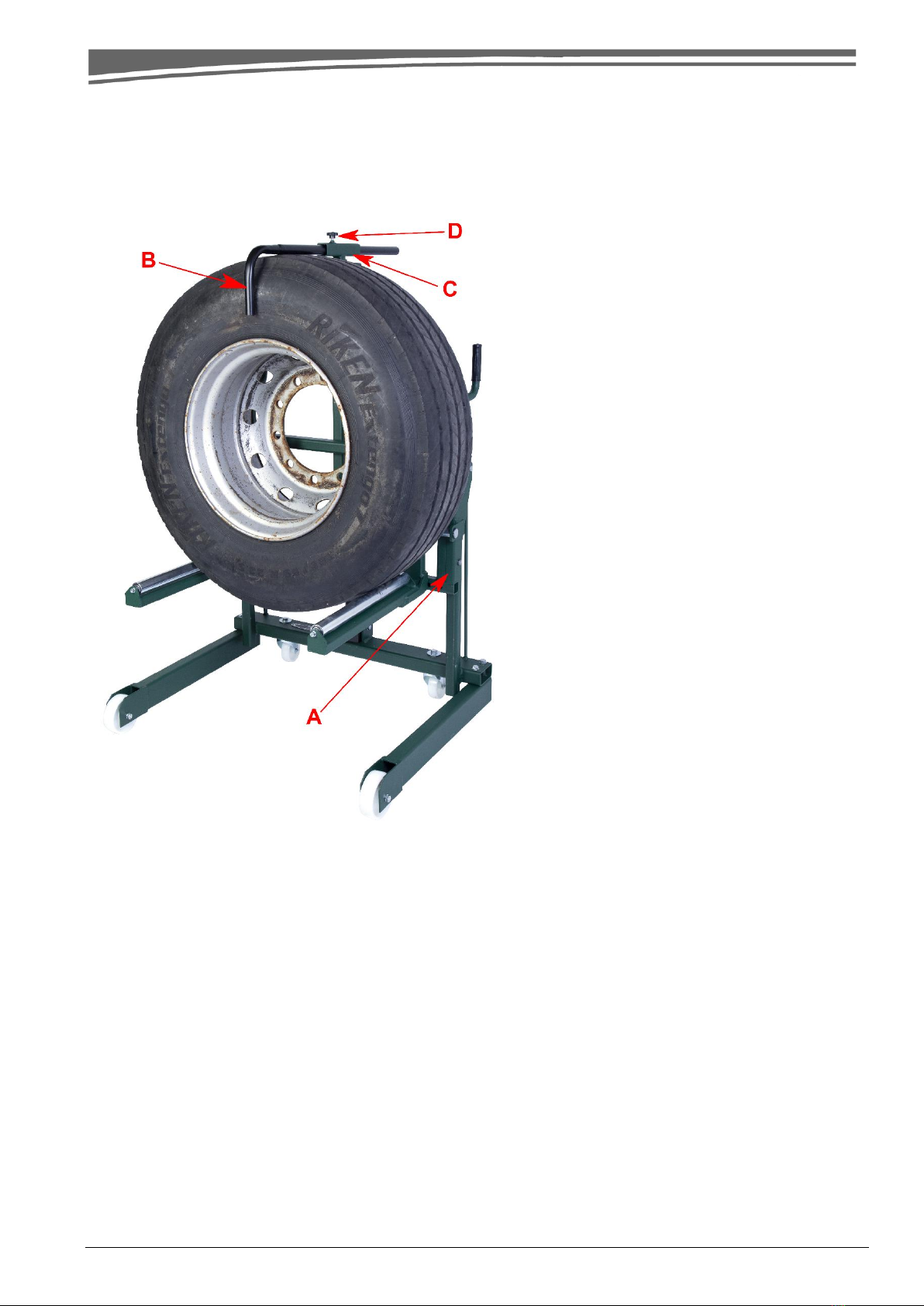
Chassis, tower, forks and other chassis parts must be checked for damage and abnormal wear.
All moving parts must be inspected, cleaned and lubricated once a month.
In case of rust, remove the rust and protect with a rustproofing agent.
Check that the dowels on the forks and rollers are fully intact and working properly.
Check that retaining rings, nuts, bolts, and mandrels are fully intact and working properly.
If the unit requires repair, repair work must be done by a person with hydraulics experience/training.
If parts on the unit are replaced, they must be replaced with original parts.
If the unit has been defective or has malfunctioned, the unit must not be used until it has been
inspected by a person with hydraulics experience/training.
On the annual inspection, the machine must be serviced by a trained professional, so the above is
checked and any problems repaired.
Oil
Oil reservoir: Contains 0.95 litres.
Use only Hydraulic Oil AWS22
Do not use brake fluid, motor oil or the like!
Troubleshooting
1. The wheel lifter does not lift to the top position: The oil level is low. Lower the tower and fill to
the edge of the hole.
2. Poor pump function (“half” pump stroke): The oil level is too high. Lower the tower fully and let
the excess oil run out of the oil plug.
3. The tower sinks: Check that the release closes correctly.
If the error persists, repair the hydraulic unit.
Disposal
Drain the oil from the unit in a responsible manner and deliver the unit and other parts to an approved
waste recipient.

(EN) 5374 WD500 G1 (EN).docx 10 / 15 2020-01-24 R1.1 S1
Knowhow is the difference
Service log
Date
Performed by
Remarks
Next service
d/m/y
Stamp or signature
-
d/m/y

(EN) 5374 WD500 G1 (EN).docx 11 / 15 2020-01-24 R1.1 S1
Knowhow is the difference
Wheel dolly assembly
Component overview for assembly
Pos.
Item
A
Chassis frame
B
Castor wheel with bolt and
washer
C
Leg
D
Fork left and right
E.
Cylinder (with oil plug)
F
Height barrier for safety bar
G1
Safety bar short
G2
Safety bar long
H
Bolt with washer for leg

(EN) 5374 WD500 G1 (EN).docx 12 / 15 2020-01-24 R1.1 S1
Knowhow is the difference
Preparation
After opening the packaging, check the product for visible damage and leakage.
Assemble the product as instructed.
Mount the two castor wheels B onto chassis frame A.
Mount the bolts with washers and
locking washers inside the chassis.
Prepare wheels, washers and
nuts.
Place the wheel and tighten
using a 19 mm wrench.
Mount the two legs C.
Place bolts with washers
internally.
Tighten using a 19 mm wrench.
Turn over the mounted chassis.
This requires 2 people!
Note that the two cable ties are
still mounted!

(EN) 5374 WD500 G1 (EN).docx 13 / 15 2020-01-24 R1.1 S1
Knowhow is the difference
Complete assembly of the chassis frame.
Mount the two forks D (note that there is a left and a right fork).
Remove the retaining ring on
the mandrel.
Pull out the mandrel and mount
the two forks (note that the
rollers should face the centre).
Push the mandrel into place and
remount the retaining ring.

(EN) 5374 WD500 G1 (EN).docx 14 / 15 2020-01-24 R1.1 S1
Knowhow is the difference
A
Mount cylinder E.
Remove the screw and washer on the cylinder.
Place the cylinder in the chassis bracket.
Mount the screw and washer as shown.
Gently tighten the screw by hand; it is tightened
mechanically after the mandrel at the top is
mounted.
Remove the retaining ring at the top and pull out
the mandrel.
Place the cylinder’s ram in the tower and push
the mandrel through the fitting.
Mount the retaining ring again.
Note: Now tighten the screw on the cylinder
using a 19 mm wrench.
Remove the cable ties locking the tower.
Remove transport plug A and mount the
plug with vent B.
Oil plug B comes fastened in the illustrated fixture.
A
B
B

(EN) 5374 WD500 G1 (EN).docx 15 / 15 2020-01-24 R1.1 S1
Knowhow is the difference
Insert the height barrier for safety bar F.
Mount the safety bar G1/ G2.
Note that there are two lengths!
A short bar for single wheels and a long bar for dual
wheels.
Mount the length that is right for the job at hand.
The safety bar that is not in use can be placed in the
profile pipe in the chassis.
The wheel dolly is now assembled and ready for use. Follow the instructions for use on page
Rev.-2020-01-24 JCN
Table of contents
Other Compac Outdoor Cart manuals