TSE DP20-4H User manual

CONDUCTOR HANDLING EQUIPMENT
5301 Shreveport-Blanchard Hwy
Shreveport, Louisiana 71107
Toll Free: 800.825.2402
Telephone: 318.929.2368
FAX: 318.929.4853
www.tse-international.com 1
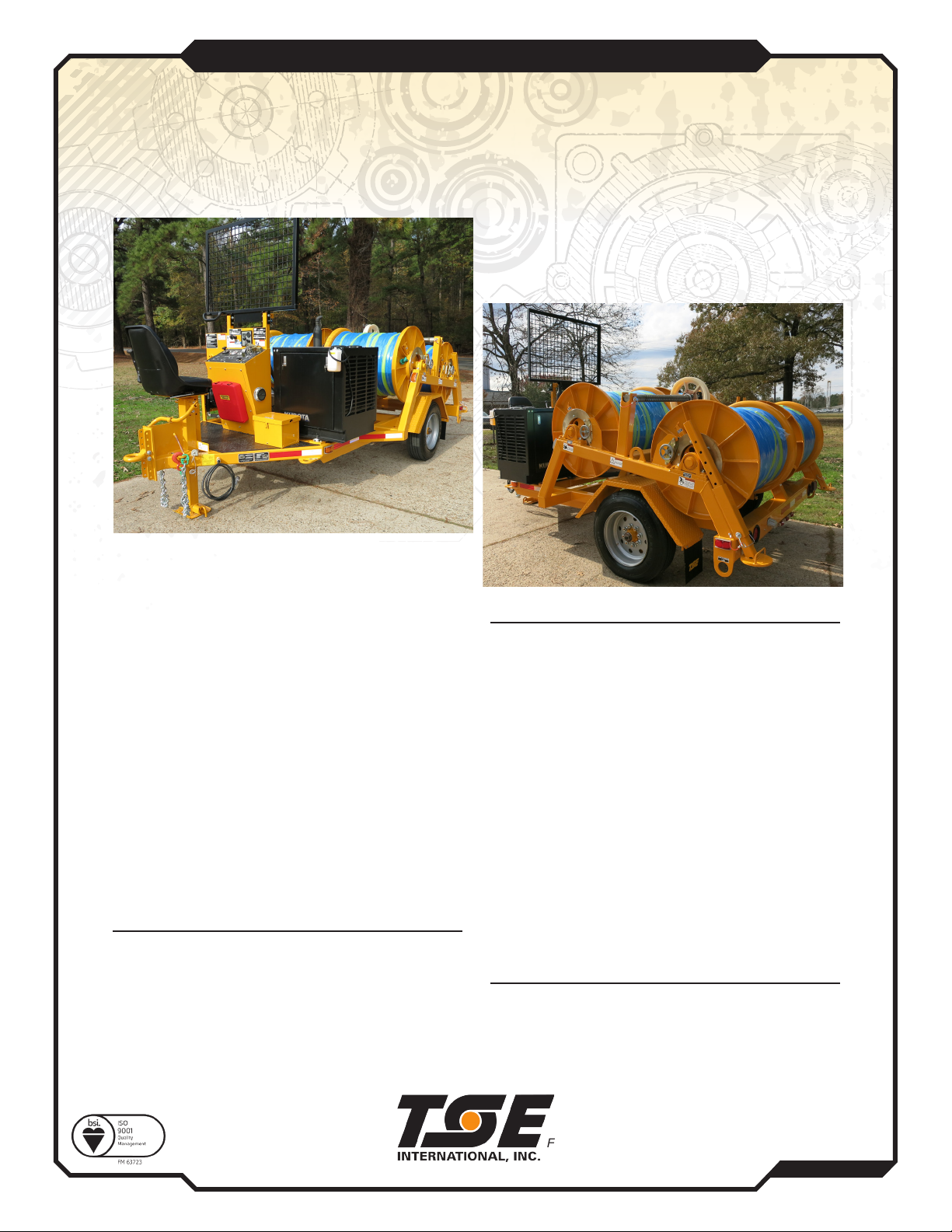
DP-20-4H
DRUM PULLER
At TSE, engineering is a process of continuous product improvement; therefore, specications are subject to change without notice.
The TSE Model DP-20-4H is a versatile, hydraulically
powered four drum puller designed for medium
distribution stringing. It can also be used as a pilot line
winder for heavier distribution. Power is transmitted from
the engine to the reels through a common hydraulic drive
train. A diamond leadscrew levelwind, accommodating
one reel at a time, aids in an even wrap during pulling.
Each reel is equipped with a mechanical clutch to allow
selective reel rotation and a mechanical brake to retard
overspin. The maximum desired linepull can be preset
prior to pulling so that the reel drive will stall if a restriction
to the line occcurs avoiding damage to the conductor,
towers and hardware.
The central operator’s console allows the operator to
completely control the pulling operation with optimum
visibilty of the pulling rope. Operator controls include
linepull, linespeed, holding brake and engine controls.
DIMENSIONS & WEIGHT (APPROX.)
Length ................................................... 15’
Width .....................................................8’
Height .................................................... 6’-4 “
Weight ................................................... 7,820 lbs.
(with rope)
STANDARD FEATURES
• 2,000 lb. linepull capacity on single full drum of rope.
• Proven hydrostatic pulling system with a hydraulic oil
cooler.
• Four pulling reels, each with a capacity for 6,000’ of
1/2” diameter rope.
• 35 hp water cooled diesel engine.
• Single axle with leaf spring suspension.
• Variable linespeed and linepull control.
• Mechanical clutch and mechanical bronze brake for
each reel.
• Spring applied-hydraulic pressure released holding brake.
• Central operator’s position for maximum safety and
visibility.
• Deluxe, adjustable operator’s seat and protective screen.
• Engraved operator’s console.
• Swing out automatic diamond leadscrew levelwind,
adjustable for individual use with all four reels.
• Steel lockable battery box.
• Front and rear drop leg mechanical jacks.
OPTIONAL EQUIPMENT
• Additional swing out automatic levelwind.
• Lockable console cover.
• Hydraulic front and/or rear jacks.

www.tse-international.com
5301 Shreveport Blanchard Hwy – Shreveport, Louisiana 71107 – USA
P: 318-929-2368 F: 318-929-4853
TSE International Inc. Warranty Policy
1. Contact the TSE International Inc. service department to discuss problem
and obtain a warranty claim number. Claim numbers will remain valid for
30 days allowing for sufficient time for submission to TSE. Warranties
claimed without a valid claim number may be denied.
2. Please retain any defective parts for a period of 60 days. TSE reserves the
right to inspect and/or evaluate any parts submitted for warranty
consideration. Should TSE elect to inspect the parts, a RGA (Return Goods
Authorization) number will be issued and the parts are to be returned
prepaid to TSE. Items not returned within 30 days will result in the RGA
closure and may result in a denial of the claim.
3. Warranty submission must be on the standard TSE International Inc. claim
form. Claims that are not will be classified as pending until proper forms are
submitted. All claims must have an estimated cost associated with each
item under discrepancy.
4. Major subcomponents are warranted under separate manufacturer
warranties. It is the responsibility of the owner/dealer of the equipment to
fill out and register all subcomponent manufactures warranties. In the
event of failure, arrangements can be made to deal with the subcomponent
supplier directly. Examples for subcomponent manufactures are:
Engines– John Deere, Cummins, Caterpillar, etc.
Claims submitted as per above TSE International Inc. Equipment Warranty policy
will be resolved within 30 days of receipt

www.tse-international.com
5301 Shreveport Blanchard Hwy – Shreveport, Louisiana 71107 – USA
P: 318-929-2368 F: 318-929-4853
Recommendations for improving this publication
are encouraged and should be forwarded to:
TSE INTERNATIONAL
5301 Shreveport-Blanchard Hwy.
Shreveport, Louisiana 71107
This is not a tension stringing operation procedures manual. No attempt is made or
implied herein to instruct the user in methods peculiar to the individual application of
the equipment described in this manual. The contents of this manual are intended as a
basis of for operation, maintenance, and parts listing of the unit in its intended and
anticipated use, as it stands alone in conjunction with other equipment.
The Equipment described in this manual is potentially dangerous if improperly or
carelessly operated. For the protection of personnel and equipment, only competently
trained operators who are critically aware of the proper procedures, operating
parameters, and limitations, potential dangers, and application of this equipment should
be allowed to touch the controls at any time.

www.tse-international.com
5301 Shreveport Blanchard Hwy – Shreveport, Louisiana 71107 – USA
P: 318-929-2368 F: 318-929-4853
PREMIUM CUSTOMER SERVICES
TSE supports its innovative products with Premium Customer Service. Our
comprehensive Service Department provides TSE customers with the service, parts,
and technical assistance they need to maintain their equipment in top operating
condition.
For Customer Service on Your
Model
Serial No.
PLEASE CALL 1-800-825-2402
Our People Care: Our Equipment is the Proof.
18-5048-01
DP20-4H

www.tse-international.com
5301 Shreveport Blanchard Hwy – Shreveport, Louisiana 71107 – USA
P: 318-929-2368 F: 318-929-4853
HOW TO ORDER REPLACEMENT PARTS
In order that we may promptly send the exact replacement part required in the least
amount of down time for you, the information listed below is necessary.
To order the replacement part, locate the part from the drawings in this manual and give
the following information:
1. Unit Model No. (From the plates on the unit’s frame)
2. Unit Serial No. (From the plate on the unit’s frame, will contain numbers only)
3. Part Number (If available)
4. Description (If part no. not available)
5. Quantity Required
On large components such as transmissions, engines, multiple pump drives, etc., the
manufacturer’s serial number and spec. number is necessary to ensure receiving the
proper replacement part.

www.tse-international.com
5301 Shreveport Blanchard Hwy – Shreveport, Louisiana 71107 – USA
P: 318-929-2368 F: 318-929-4853
WARNING
The equipment described in this manual is neither designed nor intended for any
application, alone or with in conjunction with any other equipment, that involves the
lifting or moving of persons.
Safe operation of this equipment is dependent on use in compliance with the
procedures outline in this section and the maintenance and inspection procedures in
SECTION Ill with consideration of prevailing conditions.
The equipment described in this manual is potentially dangerous if improperly and
carelessly operated. For the protection of personnel and equipment, only competently
trained operators who are critically aware of the proper procedures, operating
parameters and limitations, potential dangers, and application of this equipment should
be allowed to touch the controls at any time.
There is potential DANGER of ELECTRICAL SHOCK when operating this machine.
Ground the unit in accordance with the regulations of the using organization. Various
methods of bonding, isolation and grounding can be used; a means suitable to the user
should be selected and rigidly adhered to by ALL operating personnel.
Keep all shields and guards in place. Keep hands, feet and clothing away from power
driven parts and moving parts. Observe all warning decals placed on the machine.
Make certain all personnel are clear of this equipment before starting engine or
operation.
Before leaving the operators position, make sure that directional controls are in the
neutral position and all brakes are set.

www.tse-international.com
5301 Shreveport Blanchard Hwy – Shreveport, Louisiana 71107 – USA
P: 318-929-2368 F: 318-929-4853
EQUIPMENT WARRANTY
TSE International Inc. (hereinafter sometimes referred to as “TSE”) warrants that it will
repair f.o.b. its factory, or furnish without charge f.o.b. its factory, a similar part to
replace any material in its machinery which, during the earlier of 90 days after the said
machinery is put into operation or six months after the date of shipment of the
machinery from the plant, is proved to the satisfaction of the company to have been
defective at the time it was sold, provided that all parts claimed defective shall be
returned, properly identified, to TSE’s factory, charges prepaid.
This Warranty to repair applies only to new and unused machinery, which, after
shipment from the factory of TSE, has not been altered, changed, repaired or treated in
any manner whatsoever unless such alteration, change, repair or treatment has been
previously authorized in writing by TSE or has been performed by the authorized
service representative of TSE.
This Warranty to repair is the only Warranty either express, implied or statutory, upon
which the said machinery is sold; the companies liability in connection with this
transaction is expressly limited to the repair or replacement of defective parts, all other
damages and warranties, statutory or otherwise, being hereby expressly waived by the
purchaser.
No representative of TSE has authority to change this Warranty or this contract in any
manner whatsoever and no attempt to repair or promise to repair or improve the
machinery covered by this contract by any representative of TSE shall waive any
consideration of the contract or change or extend this Warranty in any manner
whatsoever.

www.tse-international.com
5301 Shreveport Blanchard Hwy – Shreveport, Louisiana 71107 – USA
P: 318-929-2368 F: 318-929-4853
GROUNDING EQUIPMENT AND METHODS
Grounding Equipment and Methods information is covered in the following publication:
“IEEE GUIDE TO INSTALLATION OF OVERHEAD TRANSMISSION LINE CONDUCTORS
IEEE STD 524-2003”
The above publication is available through the following organization:
THE INSTITUTE OF ELECTRICAL AND ELECTRONICS ENGINEERS, INC.
3 PARK AVENUE
NEW YORK, NY 10016-5997
USA

www.tse-international.com
5301 Shreveport Blanchard Hwy – Shreveport, Louisiana 71107 – USA
P: 318-929-2368 F: 318-929-4853
DECALS
Your equipment was shipped from the factory with the decals on the following sheet.
Should any of these decals be missing, they could prevent the proper operation and/or
maintenance of the unit which may result in personal injury or property damage.
If any of these decals are missing, please contact us for a replacement.
Order the decal(s) by stating the decal description, number, and quantity.
TSE INTERNATIONAL
5301 SHREVEPORT-BLANCHARD HWY.
SHREVEPORT, LA 71107
ATTENTION: SERVICE MANAGER
TELEPHONE: 800-825-2402
FAX: 318-929-4853


CONTENTS
DP20-4H
SECTION I INTRODUCTION
SECTION II OPERATIONS
SECTION III MAINTENANCE
SECTION IV PARTS LIST
F602339-C FINAL ASSEMBLY – DP20-4H
8602356-B GENERAL ASSEMBLY – DP20-4H (Yanmar Engine)
861207-I REELS & SHAFT ASSEMBLY
780101-C DRIVE ASSEMBLY
7601293-A HYDRAULIC SCHEMATIC
7601116-C TRAILER LIGHTING DIAGRAM - LED
7601328-A ENGINE & PUMP ASSEMBLY
7601331 CONTROL PANEL ASSEMBLY
SECTION V VENDOR INFORMATION
ENGINE(Yanmar)
PUMP
MOTOR
BRAKE
GEARBOX
AXLE

SECTION I
INTRODUCTION
GENERAL DESCRIPTION
The TSE Model DP20-4H is a trailer mounted four drum puller powered by a four cylinder diesel
engine and hydrostatic transmission. The speed, torque, and direction of the transmission are
regulated from the elevated, centrally located control panel to allow an infinitely variable control of line
tension and speed within the specified performance parameters of the unit in both the pulling and
tensioning mode of operation. Efficient cable wrapping is promoted by the leadscrew-type levelwind.
WARNING/CAUTION: WHEN THIS SIGN APPEARS ON THESE PAGES, IT INDICATES WHERE
SPECIAL ATTENTION SHOULD BE PAID TO THE INSTRUCTIONS GIVEN. PERSONAL INJURY
OR DAMAGE TO THE EQUIPMENT MAY OCCUR IF THE INSTRUCTIONS ARE NOT
FOLLOWED.
DIMENSIONS
Length 186 inches
Width 96 inches
Height 104 inches (Top of Operator Screen)
PERFORMANCE
1 Full Reel 2,000 lbs @ 3.5 MPH
4 Reels Simultaneously 500 lbs @ 2.0 MPH
Speed Range: 0-4 mph
WARNING: THESE VALUES ARE A MAXIMUM AND MUST NOT BE EXCEEDED.
REEL SPECIFICATIONS
Reel Diameter: 34 inches
Reel Width: 32 1/2 inches (Inside flanges)
Drum Diameter 12 ¾ inches
WARNING: THESE VALUES ARE A MAXIMUM AND MUST NOT BE EXCEEDED.
UNDERCARRIAGE
Axle Single 8,000 lb capacity
Tires 215/75R17.5
Brakes 12 1/4" X 3 3/8” Electric
Front Jack Manual Screw Type
Rear Stabilizers Pin Type

SECTION II
OPERATION
CONTROLS
The controls in Figure 1 are described below.
BEFORE OPERATING THIS EQUIPMENT FAMILIARIZE YOURSELF WITH ALL CONTROLS AND
THEIR FUNCTION. ONLY FULLY TRAINED PERSONNEL SHOULD OPERATE THIS
EQUIPMENT.
Figure 1: Control Panel
1. Hydraulic Pressure Gauge - This gauge shows the hydraulic pressure in the system. Do not
continuously exceed 3000 psi during the operation of the machine.
2. Linepull Control - The pressure in the hydraulic system is regulated with this control knob also
shown in Figure 2. Clockwise rotation of the Linepull Control increases pressure and therefore
increases the Linepull. Counter clockwise rotation of the Linepull Control decreases pressure and
therefore decreases the Linepull. Once the system pressure is set with the Linepull Control, the
maximum Linepull will not exceed this setting. The Linepull can be set at any level from zero to
the maximum Linepull rating.

Figure 2: Linepull Control Knob
3. Brake Control - The brake is spring applied and released by hydraulic pressure also shown in
Figure 3. To hold the reel stationary, turn the Reel Brake Lever to the APPLY position. Turn to
the RELEASE position before driving the reel.
CAUTION: THE BRAKE IS DESIGNED TO HOLD THE CONDUCTOR UNDER STATIC
CONDITIONS ONLY.
WARNING: THE HOLDING POWER OF THE BRAKES AND PROPER FUNCTIONING OF ALL
MACHINE CONTROLS MUST BE VERIFIED BEFORE THE UNIT IS PUT INTO SERVICE TO
ENSURE SAFE OPERATION. THIS IS PARTICULARLY IMPORTANT WHEN STRINGING IN THE
VICINITY OF ENERGIZED LINES.
Figure 3: Brake Control
4. Direction Control - The reel turning speed (Linespeed) and direction is controlled by a single
lever that regulates the degree of pump stroke in both directions from the NEUTRAL Position,
also shown in Figure 4. Movement of the Direction Control Lever in either direction, away from
the operator for ‘Pay Out’ and toward the operator for ‘Pull In’, increases the rotating speed of the
reel. The reel will remain stationary with the Direction Control Lever in the NEUTRAL position.

Figure 4 – Direction Control
5. Direction Lever Stop - A Stop positioned in front of the Direction Control Lever will not allow the
Lever to be put in the ‘Pay Out’ direction without the operator lifting the Stop handle to allow the
Direction Control Lever to pass. The Stop automatically falls back into place when the lever is
returned to the NEUTRAL position or to the ‘Pull In’ direction.
6. Charge Pressure Gauge - This gauge indicates the system charge pressure and should be
approximately 300 psi.
TOWING
Before towing always check the following:
1. Front and rear jacks are fully retracted
2. Operator protective screen is folded down
3. Wheel brakes are operational
4. Tires are inflated to proper pressure.
5. Wheel chocks are removed and stored away properly.
6. Lights are operational.
7. All reel shaft pins/locking pins are properly engaged.
8. Safety chains and breakaway switch connected.
FIELD SET UP
Prepare the unit for operation as follows:
1. Locate the unit on level ground if possible, ensuring that the unit is aligned properly with the line
to be pulled or tensioned.
2. Level the unit using the front and rear jacks.
3. It is highly recommended to put wheel chocks around each trailer tire to prevent movement of the
trailer.
4. PROPER ANCHORING OF THE MACHINE IS VERY IMPORTANT! See Figure 5. Anchor the
unit using the anchoring lugs provided. Use an anchor that will hold three times the maximum pull
of the unit.

Figure 5: Anchoring Diagram
5. PROPER GROUNDING OF THE MACHINE IS VERY IMPORTANT! The machine is equipped
with two grounding bars. (See figure 5.) To protect against electrical hazards due to induction or
electrical contact, the system must be connected to a proper ground rod or the electrical system
neutral. Follow proper grounding procedures as required by IEEE and/or the applicable standards
in your area. Use of a ground mat and a running ground on the conductor are highly
recommended.
6. Put a hazard barrier around the perimeter of the unit to keep unauthorized personnel away from
the equipment.
7. Perform daily inspection and preventive maintenance as required.
PRE START CHECKLIST
1. Ensure that the Direction Control (4) is in the NEUTRAL position.
2. Ensure that the Brake Control (3) is in the APPLY position.
ENGINE START-UP
The engine manufacturer’s manual, included in the Section V, contains detailed technical information
regarding the engine including start up procedure. Make sure you read and understand the operating
instructions contained therein. .
CAUTION: DO NOT ALTER THE RPM GOVERNER SETTING OF THE ENGINE. THE
HYDRAULIC PUMP IS LIMITED TO A SPECIFIC MAXIMUM RPM AND CAN BE DAMAGED IF
DRIVEN FASTER THAN THE GOVERNED ENGINE SPEED.
STOPPING THE ENGINE
1. Move the Direction Control (4) to the NEUTRAL position.
2. Move the Brake Control (3) to the APPLY position.
3. Decrease the engine speed to idle.
4. Allow the engine to idle for a few minutes to cool down.
5. Shut down the engine.

HYDRAULIC WARM UP (COLD WEATHER START-UP)
1. Start the engine.
2. Leave the Direction Control (4) in the NEUTRAL position.
3. Allow the system to run slightly above idle for twenty minutes or until the indicator gauge on the
suction filter reads less than ten inches vacuum.
4. Ensure that the Brake Control (3) is in the APPLY position.
5. Increase engine speed to half-throttle.
6. Move the Direction Control (4) to approximately half-stroke in the PULL IN direction.
7. Turn in Linepull Control (2) clockwise until the Pressure Gauge (1) reads 1,000 psi.
8. Allow system to run for:
a. Ten minutes
b. or until hydraulic oil reservoir feels warm to the touch
c. or until the indicator gauge on the suction filter reads less than five inches vacuum
In extreme cold weather operations, special low temperature hydraulic oil is recommended.
PULLING (BEGINNING WITH SLACK ROPE)
The following procedure describes how to operate the DP20-4H when it is used as a puller and the
rope is not under tension.
CAUTION: DO NOT FOLLOW THIS PROCEDURE WHEN THERE IS TENSION ON THE PULLING
ROPE.
Figure 6 – Drum Drive Pins
1. Engage Drum Drive Pins (See Figure 6.) into drum or drums to be used. (See Engaging and
Disengaging Drum Drive Pins section).
2. Increase the engine speed to full throttle. An engine operated at idle speed does not sufficiently
power the hydraulic system and may let the brake drag causing damage or overheating of the
brake and erratic control.
3. Ensure that the Brake Control (3) is in the APPLY position.
4. Pull the Direction Control (4) slightly into the PULL IN position.
5. Turn the Linepull Control (2) clockwise until the Hydraulic Pressure Gauge (1) reads 800 psi.
This presets the linepull.
6. Move the Direction Control (4) to the NEUTRAL position.
7. Confirm that the tensioner operator knows the pull is about to begin and has the tensioner
correctly set.
8. Turn the Brake Control (3) to the RELEASE position.

9. Slowly pull Direction Control (4) slightly to the PULL IN position. The pulling drum should start to
turn and tighten the pulling rope. If the pulling rope remains stationary turn in the Linepull Control
(2) clockwise slightly until the rope starts to move. When the rope starts to move, turn the Linepull
Control (2) another ½ turn to have the relief pressure in the system set just slightly above the
linepull at which you are working.
10. Slowly pull the Directional Control (4) more into the PULL IN position until the desired linespeed is
achieved.
NOTE: It may be necessary to turn the Linepull Control (2) in several times from its initial setting as
the pulling rope builds up on the pulling reel to maintain proper linepull and speed. Always turn the
Linepull Control (2) in ½ turn further than what is required to move the rope and this will ensure the
puller will stall if a snag in the pulling rope occurs.
11. To stop the pull, move the Direction Control (4) to the NEUTRAL position and turn the Brake
Control (3) to the APPLY position.
RESUMING A PULL AFTER STOPPING
This procedure describes how to start the pulling process after stopping while the pulling rope is still
under tension. This procedure assumes the Linepull Control (2) setting has not been changed from
the previous operating position during the stop.
1. Confirm that the tensioner operator knows the pull is about to begin and has the tensioner
correctly set.
2. Turn the Brake Control (3) to the RELEASE position.
3. Move the Direction Control (4) to the desired PULL IN position.
NOTE: This should start the pulling rope moving again at the same linepull as when you stopped. If
the pulling rope remains stationary, slowly turn the Linepull Control clockwise until the pulling rope
starts to move.
PAYING OUT (BEGINNING WITH SLACK ROPE)
The following procedure describes how to pay out rope when it is not under tension.
CAUTION: DO NOT FOLLOW THIS PROCEDURE WHEN THE ROPE IS UNDER TENSION.
1. Increase the engine speed to full throttle. An engine operated at idle speed does not sufficiently
power the hydraulic system and may let the brake drag causing damage or overheating of the
brake.
2. Make sure the Brake Control (3) is in the APPLY position.
3. Turn the Linepull Control (2) fully counter clockwise to give zero linepull in the pull in direction.
4. Turn the Brake Control (3) to the RELEASE position.
5. Push the Direction Control (4) slowly into the PAY OUT position. You will have to lift the Direction
Lever Stop (5) to allow the Direction Control (4) to pass beyond the NEUTRAL position. Push
Direction Control (4) more into the PAY OUT position to increase the speed.
WARNING: NEVER PUT THE DIRECTION CONTROL LEVER IN THE PAY OUT POSITION
WHEN PULLING ROPE OR WHEN THE CONDUCTOR IS UNDER TENSION!
6. To stop, put the Direction Control (4) to the NEUTRAL position. The Direction Lever Stop (5) will
fall back into place restricting movement into the PAY OUT direction once again.
Table of contents
Other TSE Construction Equipment manuals
Popular Construction Equipment manuals by other brands

Doka
Doka Xsafe plus User information

Hydro Mobile
Hydro Mobile M2 Series owner's manual

ClearSpan
ClearSpan COVERED CORRAL manual

Nordson
Nordson Fluidking manual

Worldwide Construction And Forestry Division
Worldwide Construction And Forestry Division 745 Operator's manual

Dural
Dural Z-FLEX CURVER I operating instructions