TSI Instruments Amermac 405-W User manual

READ INSTRUCTIONS THOROUGHLY BEFORE OPERATING
800.223.4540
3451 S. 40th Street
Phoenix, AZ 85040
602.437.5020
www.buytsi.com
info@buytsi.com
Fax 602.437.5025
MADE IN USA
7-6-2020
OPERATING MANUAL Portable Truers
Model 405-W

Page 2
WARNING - WEAR SAFETY GLASSES
USE CAUTION! Machine is equipped with a very sharp rotating blade.
Training is advised prior to operating. Due to physically shaving material from a tire - damage to
tires can occur and proper instruction is highly encouraged. Instructions for use are included.
Only use Truer on clean tires completely free from debris. If truing used tires remove sand, rocks
and other foreign debris from tire tread. Likewise remove debris from rims and hubs too.
Do not leave machine ON unattended.
Model 405-W: Primary Features
Top Deck
Each PortaTruer
can mount on a
stand if necessary.
(Sold separately)
Cutter Head
Cutter Blade &
Safety Cover
Lamp
Drive Roller
(Cradle)
Control Box
Manual Blade Sharpener
(to Stone Cradle)
Slide Rails
Calibration Arm
& Knob
Fig. 1
General: Remove machine from packaging materials. Special care should be taken
handling the unit due to pinch points and the sharp cutting blade.
Use unit on a clean, level surface with adequate room to maneuver and make
necessary adjustments to the machine as it is being used.
Electric Supply: 1/3 HP, 115/230 Volt, 60 Hz, 20 Amp, single phase
1/3 HP, 220 Volt, 50 Hz, 20 Amp, single phase
Overview: Portable Truers are designed to service tires mounted on an elevated vehicle.
Use the unit freestanding by itself on the ground or bolted on a Truer Stand
used in conjunction with a wheel balancer. Both methods will be explained.
Crossfeed Drive Screw
Pivot Arms
Infeed Drive Screw
GENERAL INFORMATION
Drive Roller Screw

Page 3
Set-Up
Truing a tire is based on many factors. Some are simple, some may seem complex. Remember, all
you’re doing is making tires round.
A key factor to successful tire truing is trimming off as little tread as possible. Removing too much
can gouge a tire during truing. It can also unnecessarily decrease the tire life.
For accuracy and consistency start with a clean, level surface where access to an elevated vehicle
is possible.
General awareness: Keep the machine and it’s associated parts free from damage and abuse.
The first step to “True” a tire with a Portable Truer is to prepare the tires on a vehicle. Check tire air
pressure and fill to manufacturers recommendations.
Parked vehicles can develop a flat spot on the tires. DO NOT true a tire without warming the tires or
driving the vehicle to remove the flat spot. TSI recommends using our model 975 Tire Warmer for
this purpose, or driving the vehicle at least 4 miles before truing the tires. When done lift the vehicle
so wheels are off the ground. Support axles using jack stands or a car hoist as necessary.
Make sure the required electric power to unit is not restricted.
INTRODUCTION
Why “True” a tire?
Tire truing is performed to eliminate poorly balanced tires, wheel skip, reduces balancing weights,
cupping and extends tire life and performance. Tire truing reduces wear and tear on drive trains and
suspension systems. It’s particularly useful for tires on all wheel drive vehicles and low-profile tires.
The goal for Truing tires is to make tires more symmetrically round to increase their performance
and maintain a smoother ride in a vehicle. In general not all tires are round. Once you line up the
cutter blade on the Truer to your tire and spin the tire you’ll see how far out of round the tire is.
For TSI our goal is to create confident and knowledgeable Tire Truer operators. This instruction
guide is a first step toward achieving that goal while attaining your objectives to satisfy customers.
Fig. 2
KEEP MACHINE CLEAN
AND FREE OF DEBRIS
DO NOT WEAR
LOOSE CLOTHING
The Portable Truer
Move unit around with rear
handle or frame parts. Do not
move or reposition unit using the drive
screw handles, the top deck, tail section,
drive roller arm or cutter head assembly.

OPERATING INSTRUCTIONS
The first step may be the most crucial. Loaded with many things to forget or be over looked, please
refer to these instructions often if necessary until you formulate a routine that works best for you.
1. Set machine up for start position. Sharpen blade razor sharp.
Set-Up on page 3, skimmed over preparing the tires on the vehicle. The tires were ‘exercised’ so to
speak, cleaned and elevated so the vehicle is off the ground.
How high does the vehicle have to be off the ground? High enough so when the Truer is brought up
close to the wheel the top deck surface projects an imaginary line to the center of the tire. Being
within an inch above or below tire center is acceptable. Once lifted (on jack stands for instance) the
tire treads across the face of the tires must be parallel to the ground. Refer to page 5, Fig. 6.
Front wheels on a vehicle can be difficult to access. Turning the steering wheel to the extreme left or
right to gain sufficient access is advised. Consider camber of wheel as tread face needs to remain
parallel to the ground. Tie-off the steering wheel to keep wheels from turning.
Most front wheels on a vehicle are Trued from the front of the vehicle but in some cases you may
need to True them from the backside of the wheel. Choose whichever allows maximum access.
Get machine ready
Set the callibration arm to 24 (see fig 4) As you become more experienced you may wish to change
the setting on the callibration arm. Physically move the Truer into position so top deck is perpendicular
to vehicle tire with cutter blade about 1/4” away from tire but not touching it.
Fig. 4
Use knob
to adjust
Set at 24 Fig. 5
Fig. 6
C
L
The top deck surface must project itself to be
parallel to tire center (Fig. 6) to within an inch
above or below actual center. Shown is a tire
mounted on a balancer. Whether tire is on a
vehicle or mounted on an arbor like this,
keeping the blade near this parallel plane
is preferred.
Page 4

OPERATING INSTRUCTIONS
The Porta Truer stand mentioned on Page 5, Fig. 6 is an option sold separately.
While tire is mounted on a wheel balancer, True it at the same time. Below, Fig. 7 shows an earlier
version of the stand and at right a newer version in Fig. 8. All Porta Truers can mount on either the
older or newer stand. Setup directions with or without the stand is the same.
Make sure the machine lines-up ‘on center’ to tire tread. The front edge of the Top Deck must be
perpendicular to the tire treads. Or, line the front edge of the Top Deck parallel to the tire spindle.
Other than actually Truing tires this step is the most important to ensure the Truing process goes
smoothly.
2. Adjust infeed so cutter blade almost touches tire.
When PortaTruer is in position use Infeed Drive Screw to advance cutter blade within 1/4” of tire (at
tread center.) Then use Crossfeed Drive Screw to pass cutter head / blade back and forth across the
face of the tire.
Page 5
Fig. 9 shows Pivot Arm assembled
as shipped in Position 2.
As Cutter Head pivots, access to
some tires may be restricted. If so
remove shoulder bolt from position 2
and insert into position 1. Line-up
the holes and tighten firmly.
Purpose: It limits ‘swing movement’
of Cutter Head
Consider this option when Truing
drive wheels and tires on dual rims
where access may be limited. Fig. 9
2
1
Please note: The Top Deck and Cutter Head assembly has two pivot locations for profile truing.
Fig. 7
Fig. 8
Both older and newer PortaTruers
can be mounted on either stand
PN 6418

Page 6
3. Turn on drive roller and engage to tire
Turn Drive motor ON (Fig. 10 referring to drive roller) and raise it to engage with the tire by turning
drive roller screw located at rear of machine. It’s spring loaded so no need to force it.
Remember: Tires must be free from debris!
CAUTION! PHYSICAL HARM CAN OCCUR
DO NOT allow hands, fingers or clothing to get near rotating parts or cutter blade!
Fig. 10
Flip
Safety
Cover
Fig. 11
Fig. 12
4. Turn on cutter blade motor in direction to cut.
Lift blade safety guard (Fig. 11) and turn Cutter blade switch ON in the direction which truing is to be
performed. We suggest truing the right half of the tire tread first. Start at center and move right.
Make sure Cutter Blade is razor sharp before each pass.
Turn on Lamp and adjust it to shine directly where you’re cutting.
STOP Cutter motor each time the cutter blade changes direction.
Turn infeed drive screw with the cutting gauge on it (in back of unit, see Fig. 12) to advance the
blade until it barely starts cutting.
Observe how much the tread is out-of-round to determine the
depth of the cut.
Grip the infeed drive screw (keep it from turning) & turn the
slip-wheel cutting gauge to set to zero. For example, later
when you turn the Infeed from 0 to 20 on the cutting gauge
you could take a .020” deep cut into the tire.
At the end of each cutting pass you’ll be backing the cutting
blade away from the tire so setting this at zero establishes a
starting point to return to upon going back to tire center to do
the other half of each tire.
Don’t start Cutting yet!

The Cutting Blade is specially hardened but will become dulled by embedded objects in the tread.
To insure a clean, smooth job sharpen when necessary.
Blade life depends on the operator almost as much as differences in rubber from one tire brand to
another. A blade will last longer on newer tires as opposed to older tires or tires with pebbles and
debris not cleaned properly from the tread.
The cutter gauge measures the depth of cut.
Turning it one full revolution makes the cutting blade move 1/8” (.125”) into or away from the tire.
In no case should a single cut be more than 1/32” in depth. Basically from 0 to 30 on the gauge,
which is .030 inches. Still, we suggest starting with a .020 inch cut.
There’s marks all the way around the gauge so if one forgets to pre-set the cutter gauge, you can
always use somewhere on the dial for a starting reference point. Between each mark = .005”
OPERATING INSTRUCTIONS (Cont’d)
5. Advance cutter blade to touch tire: Make dust mark at tire center.
Now, with unit on advance the cutter head / blade to barely make contact with tire. This is referred to
as a “Dust Mark.” The Dust mark gives you visual confirmation how out of round the tire actually is
and can roughly identify how much tread will be removed in order to make the tire round.
6. Set cutting depth for “rough cut” and proceed. Pass outer edge of tire.
Slowly advance the Infeed Drive Screw and set the cutter blade cut depth. Note the cutting gauge
location.
Using the Crossfeed Drive Screw on the top deck slowly traverse the top deck & cutting blade
across the right half of the tread. Turn the infeed screw to match the profile of the tire.
Observe the rate of speed you’re moving the top deck and how consistent your cut is being made.
Go faster or slower to suit the desired end-result. Continue until blade clears outer edge of tire.
7. Sharpen to razor sharp.
Upon completing the end of your first pass of the tread, make sure the cutter blade passes by the
outer edge of the tire. Back the top deck and cutting blade away from tire (be careful not to lose
where your ‘zero’ setting is) using the infeed drive screw. With motor still ON, proceed to use the
manual sharpener to sharpen the blade razor sharp in a counter clockwise direction.
More sparks will be visible when sharpening a duller cutting blade.
Remember: Always sharpen the cutter blade in the same direction.
Page 7

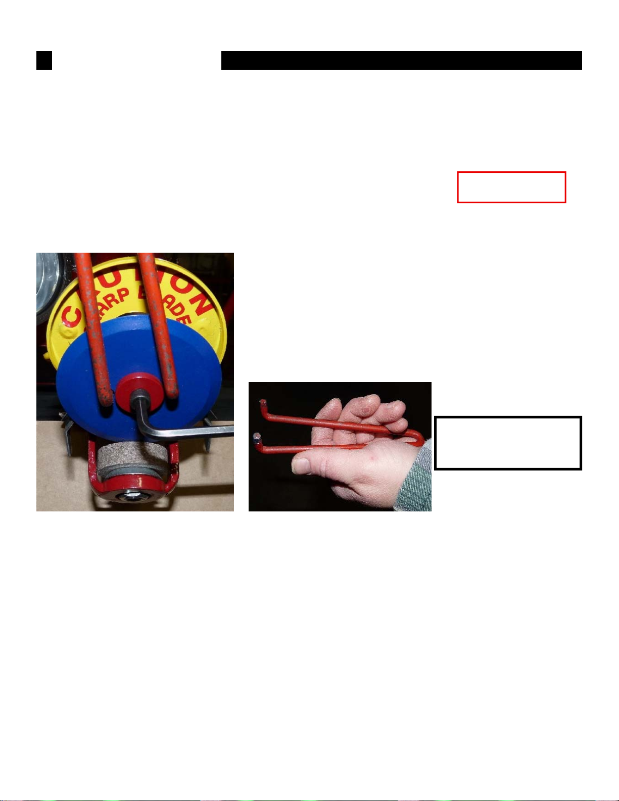
KEEP CUTTER BLADE RAZOR SHARP - KEEP THE CUTTING AREA CLEAN
Remember
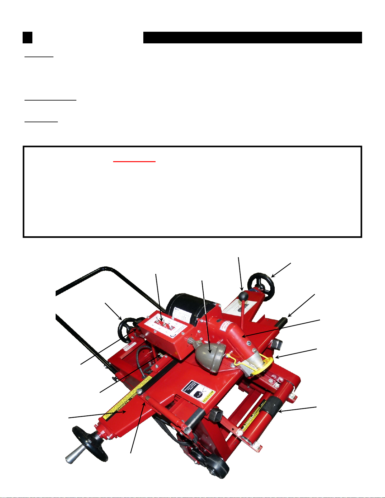
KEEP HANDS AWAY FROM SPINNING
TIRE AND CUTTING BLADE
8. Do other half of tire by repeating steps 5 thru 7.
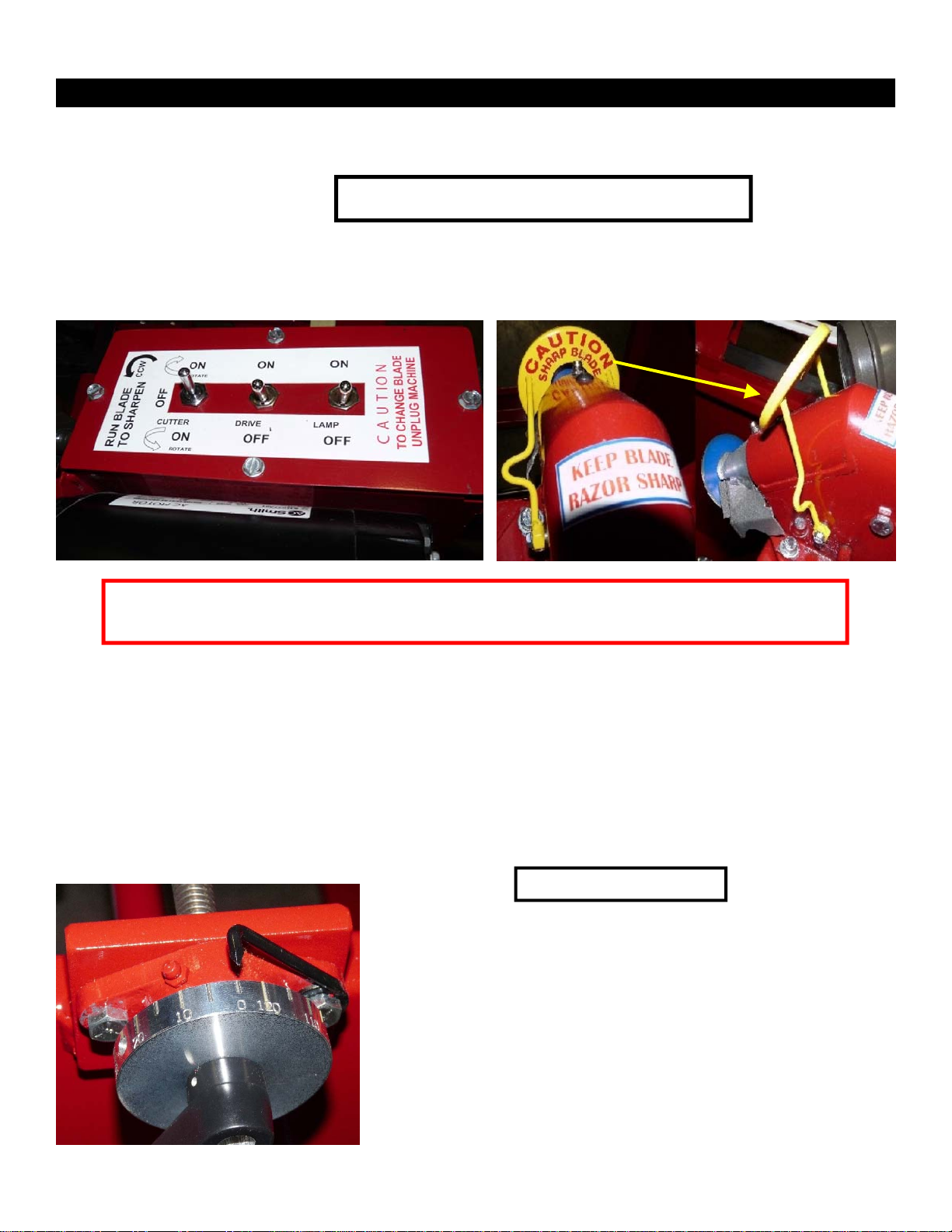
Reposition cutter blade location at the center of the tire where you first started. Turn the cutter blade
motor ON, this time Reverse the motor direction by toggling the switch toward the new direction of
truing. Set your cut and proceed to do the left side of the tire.
TSI highly recommends Truing both sides, halves of the tire in stages for each change of depth in
the tire before making the final cut. Slowing down the crossfeed drive screw traversing the top deck
and cutter blade results in a smoother end result.
It is possible a novice will prefer repeating the operation several times by taking lighter cuts until all
the high spots in the tread have been removed. Over time, after Truing many tires an operator can
gain more confidence, skill and a better understanding of what the machine can do.
When complete back cutter blade away from tire and turn cutter motor OFF. Lower safety cover.
Retract drive roller from wheel and turn motor OFF. Turn lamp OFF.
Slide PortaTruer away from tire a few inches. Clean off the unit.
Re-position cutter head and top deck to start position, making ready for the next tire or to stow away.
If tire was Trued using a wheel balancer simply pull the unit temporarily out of the way. Clean off the
machine or area before more Truing occurs.
Page 8
Please Note: While the Amermac PortaTruer can true tires on its own wheel bearings and maintain
extreme accuracy; an absolutely true tire can still be out of balance due to other factors such as rim,
hub, or drum defects and should be checked for correct balance by any good on-the-car balancer or
removed from the vehicle, balanced and remounted.
MAINTENANCE
Maintenance - Based on Truing approximately 100 tires a week.
Daily
Keep the machine clean. Remove rubber chips and debris with a brush or air nozzle. Too much
accumulated debris can complicate operation of machine as well as add to hazardous working
conditions. We recommend cleaning working contact areas after each tire is trued.
Check Blade and Sharpening Stone.
Verify Blade Safety Cover is operational.
Give the machine a good visual inspection. Check key areas of movement and make sure parts
haven’t become loose from being moved around or inadvertently bumped.

To change Cutter Blade (Fig. 13) use the Spanner
Wrench (Fig. 14) and an Allen Wrench.
Simply loosen the Socket Head Cap Screw while inserting
the Spanner Wrench into the Blade to keep it from turning.
For the Stone replacement remember to replace the paper
washers. These are shipped with replacement blades and
stones when ordered.
Once replaced tighten
blade to 30-40 ft-lbs and
stone to 15-20 ft-lbs.
UNPLUG MACHINE
FOR MAINTENANCE
Weekly
Lightly oil and lubricate all working surfaces such as slide rails, drive screws, pivot points and
contacting movable parts for longer product life and smoother operation with a silicone solution.
It should offer corrosion protection, metal wetting, water displacement and penetration to surfaces
it’s applied to. Depending on use it may be necessary to lubricate more often than weekly.
Clean and visually check Adapters for wear and tear.
Monthly
Add standard chassis grease to zerks on Cutter Head and Crank Bearings.
Check belt wear. Total belt deflection when tight is 1/4” to 3/8“ midway between pulley’s.
MAINTENANCE (Cont’d)
Fig. 13 Fig. 14
TSI suggests installing a new stone with each new blade. This will provide proper seating of the
stone to the blade, will extend the life of the blade and give better sharpening.
Note: When installing a new stone securely tighten stone nut onto stone bolt. There should be no
“wobble” of the stone if the stone nut is securely tightened.
Changing Stone
Remove Cutting Blade (Fig. 13.) Lift manual blade sharpening lever, Fig. 15 page 11, to lower stone
cradle. As supplied with each unit, work the short ended Allen Head Wrench into the Stone-Bolt Hex,
Fig. 16 page 11.
While holding the Allen Head Wrench in place, let go of the manual sharpening lever, then insert the
Special Socket into the bottom of the Stone Cradle, Fig. 17 page 11, to make contact with the Jam
Nut. Loosen and remove the old Stone and Paper Washers. In reverse order replace the Stone and
Paper Washers. Tighten securely so there’s no play left between the Stone in the Cradle and the
Bearing housed in the Stone Cradle.
Page 9

Page 10
When replacing the Cutter Blade make sure the spring loaded Carbide Blades are firmly against the
back-side of the Cutter Blade (see yellow arrow in Fig. 18.) Use the Spanner Wrench, Fig. 14 page
10, to tighten Cutter Blade.
Once Cutting Blade and Stone have been replaced recheck your work. Upon everything being
properly replaced run the unit for a few minutes to sharpen the Cutting Blade and to seat the Stone
with the new Cutting Blade.
BE VERY CAREFUL WHEN HANDLING
OR CHANGING CUTTING BLADE!
Fig. 15 Fig. 16
Fig. 18Fig. 17

TRUER MODELS 400-B & 405-W
www.buytsi.com
Each of the 405-W units measure 41” long (not including handle) x 48” wide x 24” high.
On the PortaTruer stand (Page 6, Fig. 8) it measures 37” high.
Working area for each unit requires enough space to freely maneuver around parameter of unit with
clear access applicable for an operator to safely use the controls.
800.223.4540
3451 S. 40th Street
Phoenix, AZ 85040
602.437.5020
www.buytsi.com
info@buytsi.com
Fax 602.437.5025
MADE IN USA
Table of contents
Other TSI Instruments Industrial Equipment manuals
Popular Industrial Equipment manuals by other brands

Ametek
Ametek NetWave 3.1 Operation manual

Nexen
Nexen Air Champ 5H100P-SE Installation and maintenance instructions

Phoenix Mecano
Phoenix Mecano PMZ10 installation manual

Matsing
Matsing MS-24C180 instruction manual

Busch-Jaeger
Busch-Jaeger Busch-Wachter DualLINE 6813/11 Series operating instructions

Behncke
Behncke EWT 95-15 Installation instruction