TSI Instruments TC-300 User manual

buyTSI.com - 800.223.4540
Contact us for any assistance
800.223.4540
Read this manual before operating
Tire Service International, LLC
3451 S. 40TH ST.
Phoenix, AZ 85040
Ofce: 602.437.5020
Email: [email protected]
Fax: 602.437.5025
TC-300
Wheel Crusher
Revised: April 2022

buyTSI.com - 800.223.4540
1. Only personnel trained in the operation of the TC-300 should be operating this machine.
2. Thoroughly read all safety and operating instructions before using this machine.
3. NEVER wet engine, motor, switch box or hydraulic controls. Cover these items if the machine
is to be washed. Always disconnect electrical power before attempting maintenance. Gasoline or
Diesel engines-please refer to the specied engine manuals supplied by these companies.
4. Caution: Motor rotation must be clockwise when looking at the end o f motor. If electric motor
runs counter-clockwise. reverse the wires as indicated on the motor plate diagram
Safety Requirements
Installation Requirements
Electrical Installation: The TC-300 Electric requires a minimum of 50 AMP, 230 volt, 60 cycle at the
machine. The TC-300 Electric is equipped with a 10 HP, 230/460 volt, 60 cycle standard.

buyTSI.com - 800.223.4540
Position TC-300 near tire and wheel supply to be
crushed. Place front support jack in position.
Crank jack to bring TC-300 main beam to
approximate level position.
Check to be sure breather is installed in top of
hydraulic reservoir.
Position tire to the front against the crushing
frame as shown.
Place tire & wheel into the TC-300 crushing
chamber. Place wheel with valve stem facing
up. Center wheel over beam. NOTE: It is recom-
mended that air be vented from tire.
When crushing wheels, run engine at 3/4 open
throttle.
Check engine for oil and fuel levels. Turn on fuel
valve, start engine using manufacturers
operating instructions.
Set-Up Instruction

buyTSI.com - 800.223.4540
Operating Instructions
Operate Hydraulic valve handles. Pull valve
handles towards operator to crush wheel. Push
valve handles away from operator to return
crushing wedge to starting position.
This photo illustrates the wheel being partially
crushed.
This photo illustrates the wheel being fully
crushed.
Operate hydraulic valve handles to return crush-
ing wedge to the starting position.
Slide the wheel and tire out of the TC-300
chamber. NOTE: The wheel and tire can be taken
out of either side of the machine
This photo illustrates the wheel crushed and sep-
arated from the tire.

buyTSI.com - 800.223.4540
Operating Instructions - Light Truck Tires
Place tire & wheel into the TC-300 crushing
chamber. Place wheel with valve stem facing
up. Center wheel over beam. NOTE: It is recom-
mended that air be vented from tire.
Position tire to the front against the crushing
frame as shown.
This photo illustrates the wheel being fully
crushed.
Operate hydraulic valve handles to return
crushing wedge to the starting position.
Slide the wheel and tire out of the TC-300
chamber. NOTE: The wheel & tire can be taken
out of either side of the machine
NOTE: If the light truck wheel is a lock ring style
always place lock ring down against the beam
This photo illustrates the wheel crushed and sep-
arated from the tire.

buyTSI.com - 800.223.4540
The Hour Meter indicates elapsed hours for
proper engine maintenance service intervals.
Periodically insert grease at the cylinder pivot.
Before daily operation check all bolts for tight-
ness on the movable wedge.
This adjustment controls low to high pressure
shift point. If motor bogs down-loosen lock nut
and turn Allen screw counter clockwise 1 /2 turn
and retry
Once every 6 months, remove wheels & hubs
from axle and pack the wheel bearings with a
wheel bearing grease.
This photo illustrates the Oil lter location on the
engine. Replace lter every 6 months for smooth
engine operation
NOTE: Review Engine Manufacturer’s manual
for more info on servicing engines
Maintenance

buyTSI.com - 800.223.4540
Every 6 months check battery condition
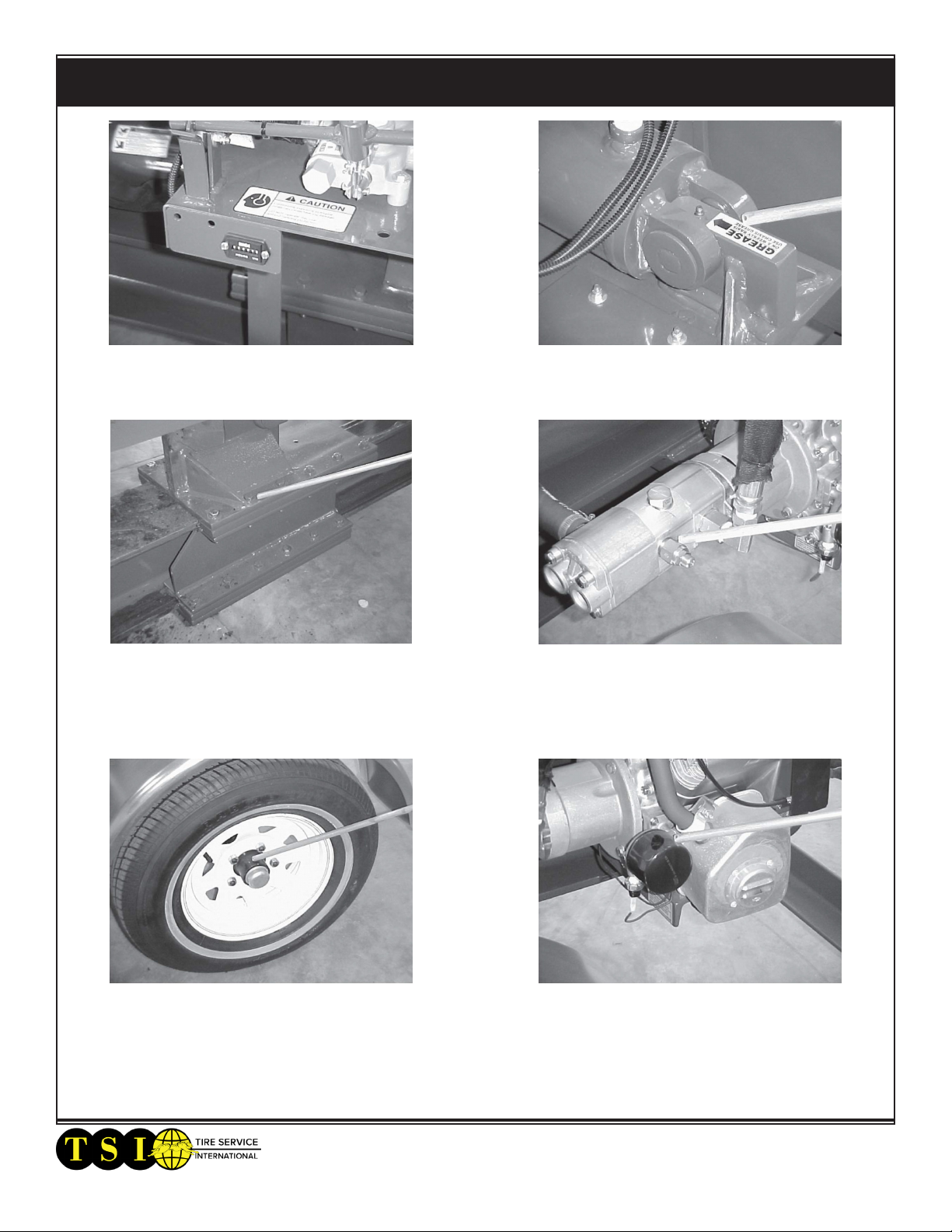
This photo illustrates the adjustment location of
the hydraulic pump pressure to the valve. The
gauge should read 2800-3000 PSI when the ram is
fully extended. To increase pressure, rst remove
large Hex nut. Then using a Hex Allen wrench-
turn adjustment screw to the right 1/4 turn at a
time & recheck until pressure is 2800-3000 PSI.
Replace oil ler every 6 months. Use TSI P/N
10130E for the replacement element
Check hydraulic oil reservoir level by viewing
the sight glass. Oil level should be approximately
3” -5” from the top.
NOTE: HYDRAULIC FLUID SHOULD BE
DRAINED ANO REFILLED EVERY 6 MONTHS.
USE UNIVERSAL AUTOMATIC TRANSMIS-
SION FLUID-SAE 20 OR SAE 30
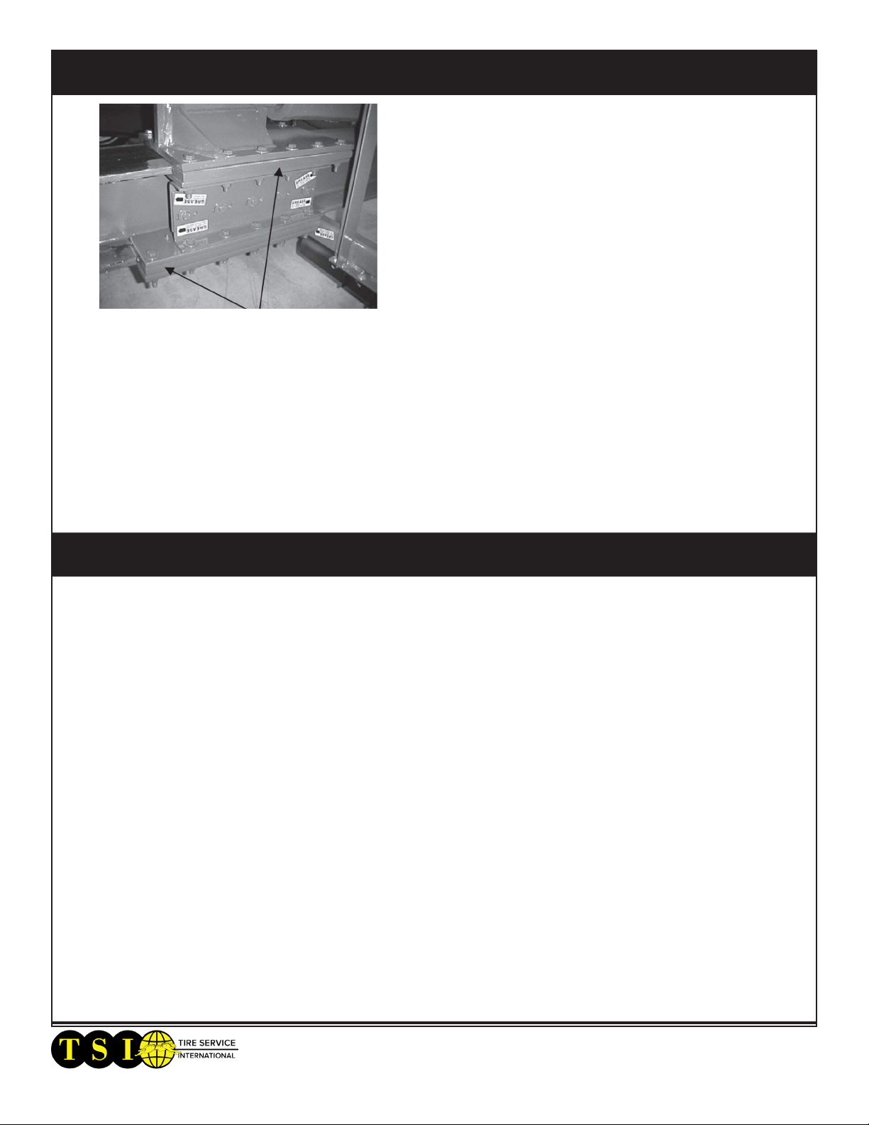
If the valve “kicks out” on the arms return stroke,
the detent will have to be tightened slightly.
Loosen lock nut as shown. Tighten outer nut 1/4
turn and tighten lock nut. Continue to crush. If it
“kicks out” again, readjust it another 1 /4 turn.
Maintenance

buyTSI.com - 800.223.4540
Maintenance
The crushing wedge has space wear bars on both
the upper and lower slides. These wear bars may
need adjusting. Loosen 6 upper and 6 lower cap
screws and slide wear bars up to beam ange.
Leave 1/32 clearance between beam and wear
bar. If wear bars are worn too much, remove bars
and turn side to side. This will give a new side to
guide on. DO NOT ALLOW SLIDE BOLTS TO
LOOSEN. KEEP BOLTS TIGHT TO 100 FT-LBS &
ADJUST SLIDE PLATES IF NECESSARY.
Notes

buyTSI.com - 800.223.4540
Optional - Roller Table Kit #6114

buyTSI.com - 800.223.4540
Drawing

buyTSI.com - 800.223.4540
Parts List
PARTS LIST PARTS LIST
ITEM PART N. DESCRIPTION QTY ITEM PART NO. DESCRIPTION QTY
1 5519 FENDER WELDMENT RH & LH 2 31 3081 SAFETY CHAIN W/HOOK 2
2 5534 HANDLE WELD 2 32 3084 TIRE, 185 X 13 2 PLY 2
3 5535-01 PIVOT WELD 1 33 3162 BATTERY CABLE 16" (POS) 1
4 5578 VALVE MOUNT WELD 1 34 3163 BATTERY CABLE 26" (NEG) 1
5 5600 MAIN FRAME WELD ASSEMBLY 1 35 3323 SLIDE PLATE 1
6 5602 VERTICAL PUSHER ASSEMBLY 1 36 3324 LOWER SLIDE 4
7 365.028 MACH SCREW 10-32 X 3/8 2 37 3325 SPACER SLIDE 4
8 206 HHCS 1/2-13 X 1-1/2 GRD 8 10 38 3330 JACK 10" LIFT 2000# 1
9 212 NUT 3/8-16 HEX NYLOK 22 39 3330-1 SNAP RING 1
10 223 NUT 1/2-13 SELF LOCK 36 40 3330-2 PIN AND SPRING 1
11 224 WASHER 1/2 FLAT 48 41 3397 SPINDLE AXLE - RH 1
12 226 NUT 1/4-20 SELF LOCK 2 42 3398 SPINDLE AXLE - LH 1
13 230 GRIP, PLASTIC 1/2 X 3-1/2 2 43 3478 HHCS 5/16 X 1-1/4 2
14 445 WASHER 1/4 FLAT WROUGHT 2 44 3500 HHCS 3/8-16 X 1-1/2 12
15 447 HHCS 3/8-16 X 1-1/4 10 45 3501 FITTING 1/8 NPT STRAIGHT ZERK 12
16 485 HHCS 1/2-13 X 2-3/4 24 46 4426 HOUR METER 1
17 566 NUT 5/16 HEX NYLOK 2 47 10197B BATTERY COVER 1
18 700 WASHER 3/8 FLAT 44 48 10407 BATTERY POST GUARD, RED-POS 1
19 1318 WASHER 5/16 FLAT 4 49 10408 BATTERY POST GUARD, BLACK-NEG 1
20 3025-1 HUB, WHEEL 2 50 10664 RING BOOT, STARTER END 1
21 3025-2 SEAL, BEARING 4 51 10934 SLIDE SPACER 4
22 3025-3 BEARING, TAPERED 4 52 11578 PLATE, SLIDER ADJUSTMENT TOP 2
23 3025-4 NUT, SPINDLE 2 53 11579 PLATE, SLIDER ADJUSTMENT BOTTOM 2
24 3025-5 COTTER PIN 2 54 3155 RUBBER STRAP 10" 1
25 3025-6 WHEEL HUB 2 55
26 3025-7 WHEEL LUG 10 56
27 3027 TRAILER COUPLER 3500# 2 57
28 3033 BATTERY 12 VOLT 1 58
29 3034 WHEEL 13" 5-HOLE 2 59
30 3080 HHCS 1/2-13 X 4-1/2 2 60

buyTSI.com - 800.223.4540
Warranty and Return Policy
Warranty & Workmanship you can depend on.
With over 30 years of manufacturing experience we maintain the ability to provide competitive
prices while employing and manufacturing the majority of our products in the USA. Pride in
our workmanship and standing behind each and every product is not just our claim but our
uncompromising responsibility.
Tire Service International equipment is warranted to be free from defects in materials and
workmanship for a period of one year from the date of original purchase to the original owner.
Repair labor is warranted for 90 days from the date of original purchase. Bushings, blades, bearings
and normal wear and tear are not covered under warranty. Careless handling, negligence, misuse,
abuse, mutilation, improper operation, making unauthorized repairs, additions, and or alterations
automatically cancel this warranty and relieves TSI of any obligation. Cheetah tanks claimed to be
defective while under warranty will be evaluated at our manufacturing plant and either repaired
if possible or exchanged and returned or credit issued to the customer account at our discretion.
Damage resulting from dropping the tanks will not receive warranty consideration. Warranty parts
need to be returned prepaid to the plant for credit. Any replacement parts shipped from the plant
will be shipped at the customer's expense. Machines requiring warranty work must be brought to
the manufacturing plant in 201 Chelsea Rd, Monticello, MN or to a repair facility authorized by TSI.
!!WARNING!! Goods returned without an RGA will be refused. A Returned Goods Authorization
form must be obtained before returning any material or goods. All non-warranty returns will be
subject to a 15% restocking fee plus any additional charges for reconditioning/repacking.
Visit www.buyTSI.com for any additional information. Also be sure to follow us on all the Socials,
and subscribe to our YouTube channel for all our product videos.
Copyright © 2022 Tire Service International, LLC
No part of this manual may be reproduced
without specic approval from Tire Service
International, LLC.
Register your product
online!
www.buytsi.com/registration
Table of contents
Other TSI Instruments Industrial Equipment manuals