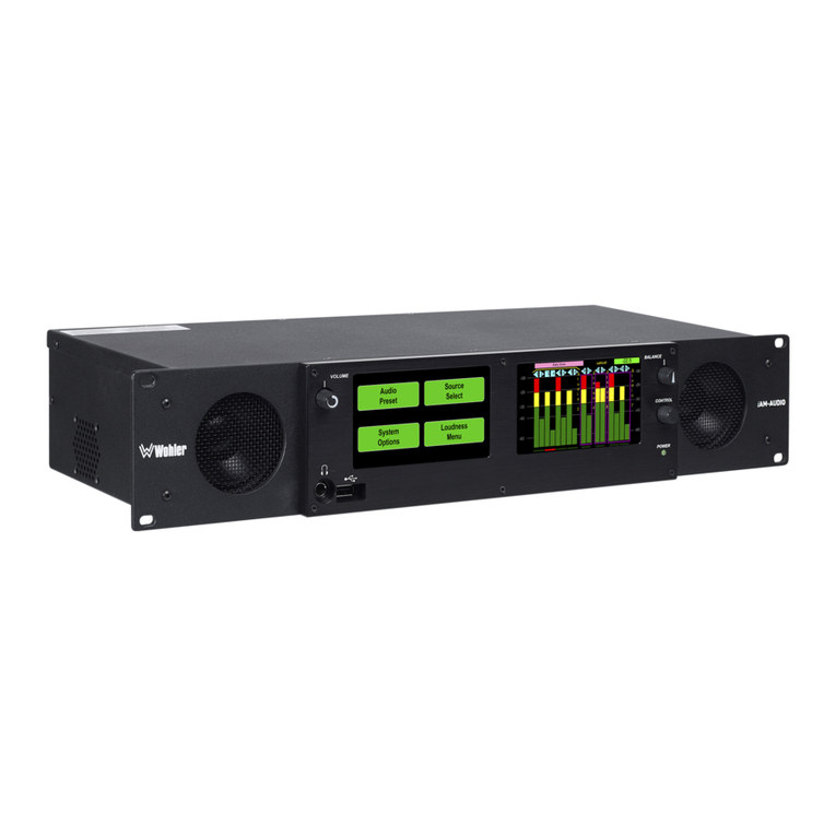
TSL MPA1 Series User manual

MPA1 Audio Monitoring Range
Installation and Operation Manual
Version 1.0

Page 2of 72
Version History
Issue
Date
Change Details
1
01/02/18
Preliminary Guide
2
05/10/18
Version 1.0

Page 3of 72
Contents
Introduction ....................................................................................................................................................5
MPA1-SOLO-SDI Installation ...........................................................................................................................6
MPA1-SOLO-SDI Functional Schematic...........................................................................................................7
MPA1-MIX-SDI Installation .............................................................................................................................8
MPA1-MIX-SDI Functional Schematic.............................................................................................................9
MPA1-SOLO-MADI Installation .....................................................................................................................10
MPA1-SOLO-MADI Functional Schematic.....................................................................................................11
MPA1-MIX-MADI Installation .......................................................................................................................12
MPA1-MIX-MADI Functional Schematic .......................................................................................................13
MPA1-SOLO-DANTE Installation ...................................................................................................................14
MPA1-SOLO-DANTE Functional Schematic...................................................................................................15
MPA1-MIX-DANTE Installation .....................................................................................................................16
MPA1-MIX-DANTE Functional Schematic.....................................................................................................17
Initial Setup...................................................................................................................................................18
Accessing the Webpage of your MPA1.........................................................................................................19
MPA1-SOLO-SDI Webpage............................................................................................................................20
MPA1-SOLO-MADI Web Page.......................................................................................................................24
MPA1-SOLO-DANTE Web Page.....................................................................................................................28
MPA1-MIX-SDI Web Page .............................................................................................................................32
MPA1-MIX-MADI Web Page .........................................................................................................................39
MPA1-MIX-DANTE Web Page .......................................................................................................................46
Operation......................................................................................................................................................53
MPA1-SOLO-SDI Operation...........................................................................................................................54
MPA1-SOLO-MADI Operation.......................................................................................................................55
MPA1-SOLO-DANTE Operation.....................................................................................................................56
MPA1-MIX-SDI Operation.............................................................................................................................57
MPA1-MIX-MADI Operation .........................................................................................................................59
MPA1-MIX-DANTE Operation .......................................................................................................................61
MPA1-SOLO-SDI Front Panel Display............................................................................................................63
MPA1-MIX-SDI Front Panel Display ..............................................................................................................65
MPA1-SOLO-MADI Front Panel Display........................................................................................................66
MPA1-MIX-MADI Front Panel Display ..........................................................................................................68
MPA1-SOLO-DANTE Front Panel Display......................................................................................................69
MPA1-MIX-DANTE Front Panel Display ........................................................................................................71

Page 4of 72

Page 5of 72
Introduction
The MPA1 Range of Audio Monitors provide high-quality confidence monitoring in a compact 1RU design.
At just 100mm deep and less than 4kg, MPA1 Audio Monitors are ideally suited for environments where
space and weight is a premium, such as OB Trucks and Flyaways.
Designed for ease of use, all MPA1 Audio Monitors can be controlled directly from the front panel, or
remotely over an Ethernet network using a suitable Web-Browser or control system using SNMP.
This manual covers the following Audio Monitoring Products within the MPA1 Range:
The MPA1-SOLO variants provide instantaneous selection and monitoring of any incoming audio source,
whilst the MPA1-MIX variants also allow for multiple monitor mixes, comprising up to 8 audio pairs, to be
created, stored and recalled with ease.
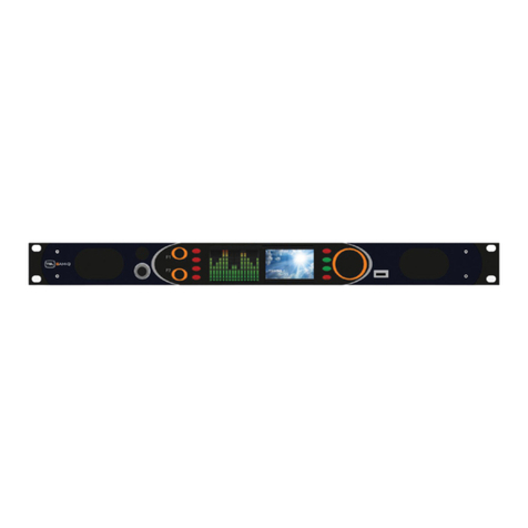
Front Panel for MPA1-SOLO Variants
Front Panel Layout for MPA1-MIX-Variants
MPA1-SOLO-SDI
MPA1-MIX-SDI
MPA1-SOLO-MADI
MPA1-MIX-MADI
MPA1-SOLO-DANTE
MPA1-MIX-DANTE

Page 6of 72
MPA1-SOLO-SDI Installation
The MPA1 Audio Monitoring Range has been designed to be quick and easy to install, requiring minimal
installation effort. Input and output connectivity for each MPA1 Model can be seen below:
MPA1-SOLO-SDI
Product
Inputs
Outputs
Other
MPA1-SOLO-SDI
2 x 3G/HD/SD-SDI
1 x AES3 (75 ohm)
2 x Analogue Inputs
(Balanced)
1 x 3G/HD/SD-SDI
(reclocked)
2 x Analogue Outputs
(Balanced)
1 x Headphone Output
1 x HDMI Monitoring
Output
1 x 1Gig/E Ethernet
Port (Management and
Control)
1 x USB Port (Software
Updates and
Configuration)
1 x IEC Power Inlet

Page 7of 72
MPA1-SOLO-SDI Functional Schematic

Page 8of 72
MPA1-MIX-SDI Installation
The MPA1 Audio Monitoring Range has been designed to be quick and easy to install, requiring minimal
installation effort. Input and output connectivity for each MPA1 Model can be seen below:
MPA1-MIX-SDI
Product
Inputs
Outputs
Other
MPA1-MIX-SDI
2 x 3G/HD/SD-SDI
1 x AES3 (75 ohm)
2 x Analogue Inputs
(Balanced)
1 x 3G/HD/SD-SDI
(reclocked)
2 x Analogue Outputs
(Balanced)
1 x Headphone Output
1 x HDMI Monitoring
Output
1 x 1Gig/E Ethernet
Port (Management and
Control)
1 x USB Port (Software
Updates and
Configuration)
1 x IEC Power Inlet

Page 9of 72
MPA1-MIX-SDI Functional Schematic

Page 10 of 72
MPA1-SOLO-MADI Installation
MPA1-SOLO-MADI
Product
Inputs
Outputs
Other
MPA1-SOLO-MADI
1 x MADI (75 ohm)
1 x MADI (SFP cage for
optional SFP module)
8 x Analogue Inputs
(Balanced)
1 x MADI (75 ohm)
reclocked
2 x Analogue Outputs
(Balanced)
1 x Headphone Output
1 x 1Gig/E Ethernet
Port (Management and
Control)
1 x USB Port (Software
Updates and
Configuration)
1 x IEC Power Inlet

Page 11 of 72
MPA1-SOLO-MADI Functional Schematic

Page 12 of 72
MPA1-MIX-MADI Installation
MPA1-MIX-MADI
Product
Inputs
Outputs
Other
MPA1-MIX-MADI
1 x MADI (75 ohm)
1 x MADI (SFP cage for
optional SFP module)
8 x Analogue Inputs
(Balanced)
1 x MADI (75 ohm)
reclocked
2 x Analogue Outputs
(Balanced)
1 x Headphone Output
1 x 1Gig/E Ethernet
Port (Management and
Control)
1 x USB Port (Software
Updates and
Configuration)
1 x IEC Power Inlet

Page 13 of 72
MPA1-MIX-MADI Functional Schematic

Page 14 of 72
MPA1-SOLO-DANTE Installation
MPA1-SOLO-DANTE
Product
Inputs
Outputs
Other
MPA1-SOLO-DANTE
1 x 1Gig/E Ethernet
Port (Dante/AES67)
1 x MADI (75 ohm)
1 x MADI (SFP cage for
optional SFP module)
8 x Analogue Inputs
(Balanced)
1 x MADI (75 ohm)
reclocked
2 x Analogue Outputs
(Balanced)
1 x Headphone Output
1 x 1Gig/E Ethernet
Port (Management and
Control)
1 x USB Port (Software
Updates and
Configuration)
1 x IEC Power Inlet

Page 15 of 72
MPA1-SOLO-DANTE Functional Schematic

Page 16 of 72
MPA1-MIX-DANTE Installation
MPA1-MIX-DANTE
Product
Inputs
Outputs
Other
MPA1-MIX-DANTE
1 x 1Gig/E Ethernet
Port (Dante/AES67)
1 x MADI (75 ohm)
1 x MADI (SFP cage for
optional SFP module)
8 x Analogue Inputs
(Balanced)
1 x MADI (75 ohm)
reclocked
2 x Analogue Outputs
(Balanced)
1 x Headphone Output
1 x 1Gig/E Ethernet
Port (Management and
Control)
1 x USB Port (Software
Updates and
Configuration)
1 x IEC Power Inlet

Page 17 of 72
MPA1-MIX-DANTE Functional Schematic

Page 18 of 72
Initial Setup
TSL Products recommends connecting your MPA1 Audio Monitor to an Ethernet network during initial set-
up and configuration.
Full configuration of your MPA1 Audio Monitor can be achieved by way of a suitable Client PC and Web-
browser.
Setting the Control IP Address of your MPA1 Audio Monitor
All MPA1 Audio Monitors are shipped with a DHCP setting default to ‘DHCP ‘On’.
To determine the current IP address of your MPA1, push and hold the SELECT/MENU encoder for 3 seconds
to access the Settings Menu.
The Settings Menu will now appear on the front panel
display of your MPA1, with the current IP Address shown.
Using the SELECT/MENU encoder, you can scroll through the
Settings Menu to highlight a Settings Sub-Menu of your choice.
The availability of Sub-Menus is depicted by the presence of the
following symbol: >>
With the IP Address Sub-Menu highlighted as shown, briefly push the SELECT/MENU encoder to access the
Network Settings Menu (see below).
The SELECT/MENU encoder will now allow you to scroll through,
select and modify the Network Settings of your MPA1 in
accordance with the guidelines set by your Network
Administrator.
Once complete, select BACK to return to the Settings Menu. You
can exit the Settings Menu by pushing and holding the
SELECT/MENU encoder for 3 seconds once more.

Page 19 of 72
Accessing the Webpage of your MPA1
Configuring your MPA1 Audio Monitor using a Client PC and Web-Browser
With your MPA1 connected to an Ethernet network, you can remotely control and configure your MPA1
using a Client PC and Web-Browser.
The MPA1 Webpage allows you to optimise your MPA1 for your environment and the workflow you need
to support.
Settings such as the brightness of the front panel display, which sources may be selected from the front
panel of the unit and the behaviour of the MPA1 when used with Headphones can all be set using the
MPA1 Webpage.
Enter the IP Address of your MPA1 into a Web-Browser
The MPA1 Webpage comprises multiple Tabs, providing quick navigation to specific sections of the MPA1
configuration, providing quick and easy setup.
Separate Tabs for LIVE VIEW, NAMES, CONFIGURATION and NETWORK SETUP are present on the Webpage
belonging to all MPA1-SOLO variants, whilst an extra ROUTING Tab can be found on all MPA1-MIX variants.
MPA1-SOLO- SDI, MPA1-SOLO-MADI and MPA1-SOLO-DANTE
MPA1-MIX- SDI, MPA1-MIX-MADI and MPA1-MIX-DANTE
The following pages detail the contents and settings available using the MPA1 Model.

Page 20 of 72
MPA1-SOLO-SDI Webpage
Clicking on the LIVE VIEW Tab of the MPA1-SOLO-SDI Webpage displays the following:
Element
Function
Notes
1
Switch to Mute Headphone Output
Red when Muted, Grey when Active
2
Headphone Output Level adjustment
Adjust as required
3
Switch to Mute the Loudspeaker Output
Red when Muted, Grey when Active
4
Loudspeaker Output Level adjustment
Adjust as required
5
Input Selection
Switches between SDI 1, SDI 2 and AES +
Analogue Input Monitoring
6
Audio Level Meter Display
Displays Audio Levels in accordance with Input
Selection
7
Stereo/Mono Switch
Switches Audio Monitoring Selectors between
Single Audio Channel and Audio Pair mode.
8
Screen Mode Switch
Switches front panel display between Audio
Metering and SDI Video Source.
9
Signal Format Display
Format display of SDI 1, SDI 2 and AES3 Inputs
10
Audio Monitor Selectors
Selects the Single Audio Channel or Audio Pair
routed to the Headphone and Loudspeaker
Outputs.
1
2
3
4
5
7
10
6
8
9
This manual suits for next models
6
Table of contents
Other TSL Speakers System manuals
