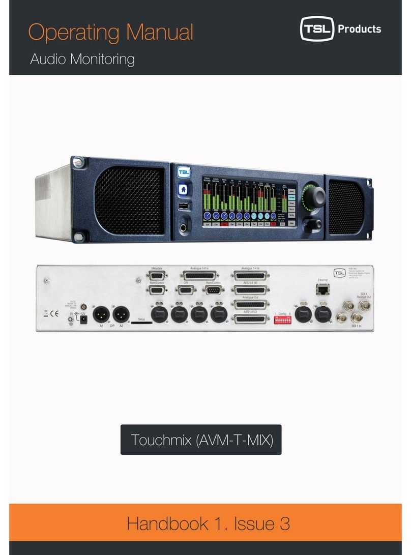
TSL AMU2-BHD+ User manual

AMU2-BHD+
Audio monitoring
Unit
Handbook
TSL Products
Units 1-2, First Avenue, Globe Park, Marlow, Bucks, SL7 1YA
Telephone +44 (0)1628 564610

AMU2-BHD+-6 1 ISSUE 6

AMU2-BHD+-6 2 ISSUE 6
SAFETY
Installation.
Unless otherwise stated TSL equipment may be installed at any angle or position
within an operating temperature range of 5°- 30°C .
All TSL equipment conforms to the EC Low Voltage Directive:
EC Low Voltage Directive (73/23/EEC)(OJ L76 26.3.73)(LVD).
Amendment: (93/68/EEC) (OJ L220 30.8.93).
In all cases, the frame of the equipment must be earthed on installation.
The earth pin on the IEC mains inlet connector is connected to the metal frame of
the equipment, to 0 volts on the internal DC PSU and to signal ground, unless
otherwise stated. All metal panels are bonded together.
Due consideration for cooling requirements must be given when mounting the
equipment. Ideally 1RU of rack space should be left above and below the unit.
Check that the fuse rating is correct for the local power (mains) supply.
Replacement fuses must be of the same rating and type for continued protection
against fire risk.
Do not switch on until all connections are made.
WARRANTY, MAINTENANCE AND REPAIR
All TSL equipment is guaranteed for one year from the date of delivery to the
customer’s premises. If the equipment is to be stored for a significant period,
please contact TSL concerning a possible extended warranty period.
Failure during warranty
If any TSL product should fail or become faulty within the warranty period, first
please check the PSU fuses.
All maintenance work must be carried out by trained and competent personnel.
Technical support information
E-Mail address: support@tslproducts.com
Telephone Support Number: +44 (0) 1628 564610

AMU2-BHD+-6 3 ISSUE 6
TSL Returns Procedure
Please telephone +44 (0)1628 564610 and ask for Support who will provide a
Returns Number. This will enable us to track the unit effectively and will provide
some information prior to the unit arriving.
For each item, this unique Returns Number must be included with the Fault
Report sent with the unit.
A contact name and telephone number are also required with the Fault Report
sent with the unit.
Fault report details required.
•Company:
•Name:
•Address:
•Contact Name:
•Telephone No:
•Returns Number:
•Symptoms of the fault (to include switch setting positions, input signals etc):
Packing
Please ensure that the unit is well packed as all mechanical damage is
chargeable. TSL recommends that you insure your equipment for transit damage.
The original packaging, when available, should always be used when returning
equipment..
If returned equipment is received in a damaged condition, the damage
should be reported both to TSL and the carrier immediately.

AMU2-BHD+-6 4 ISSUE 6
Contents
1.0 Introduction
2.0 Front Panel Controls
2.1 Input and Meter Selection Buttons
2.2 Output Switching
3.0 Pin-out Details
3.1 Analogue XLR Connectors
3.2 AES/EBU XLR Connectors
3.3 Analogue Output Connector – D25 Socket Pinout
3.4 AES Input/Output Connector – D25 Socket Pinout
3.5 Control Connector - D9 Socket
3.6 External Connector - D15 Plug
3.7 Configuration Switch Functions
4.0 LS Output
5.0 General Notes
6.0 Specification
7.0 Front and rear view
8.0 Block Schematic

AMU2-BHD+-6 5 ISSUE 6
AMU2-BHD+ AUDIO MONITORING UNIT
1.0 Introduction
The AMU2-BHD+ is a full rack 2RU x 310mm deep Audio Monitoring Unit with a
106 segment bargraph.
The following features are standard:
•Two HD/SDV auto sensing input with Group select.
•Four AES/EBU inputs.
•Two switch selectable stereo analogue inputs.
•One TSL bargraph.
•Phase reverse switch.
•Phase correlation bargraph.
•Re clocked output of either HD or SDV
•Decoded PAL/NTSC composite.
•Optional additive output switch selection.
•Additional SDV output if SDV is used on input
•Headphone outputs with LS muting.
•Variable stereo line output.

AMU2-BHD+-6 6 ISSUE 6
2.1.1 TSL Bargraph
Set-up Menus.
These are accessed via the select & change buttons located between the two
alphanumeric displays to the left of the unit (see diagram above). The top display
shows the function & the bottom gives the state.
These are accessed via the select & change buttons located between the two
alphanumeric displays to the left of the unit (see diagram above). The top display
shows the function & the bottom gives the state.
1) Pressing select once gives:
P E A K
H D 0
The zero toggles between 0 , 1 and 2 when the change button is pressed. 0 is off,
and 1 is on and the highest level point is displayed. HD 2 operates only in the
PPM mode and displays the level numerically with the reference marker. With HD
0 selected the alphanumeric display is off.

AMU2-BHD+-6 7 ISSUE 6
2) Pressing select a second time gives:
D I S P
B A R
All the LEDs are lit up to the highest level displayed.
Pressing the change button gives:
D I S P
D O T
Only the highest level LED is lit.
3) Pressing select a third time gives:
R S P N
1ms
Pressing the change button gives:
.1ms
This changes the response for the relevant scales.
(0.1ms,1ms, 5ms 10ms, and VU integration times.)
4) Pressing select a fourth time gives:
I D 0
O N
This enables the unit to display the reference markers which are nominally set to
0dB. These are set as follows for the appropriate scales fitted: PPM 4 for UK,
TEST for EBU, - 4 for VU, - 6 for DIN, 0 or Test for Nordic, -18dB or - 20 dB for
Digital.
When the change button is depressed the markers are not displayed and an
OFF indication is displayed in the lower display.

AMU2-BHD+-6 8 ISSUE 6
5) Pressing select for a fifth time gives:
B R G T
Depressing the change button changes the brightness or intensity of the display.
Successive presses decrease brightness.
6) Pressing select for a sixth time gives:
I / P :
A n l g
Depressing the change button changes the input from Analogue to digital (AES).
7) Pressing select for a seventh time gives:
S C L E
E B U
Depressing the change button defines which scale is in use. (EBU, DIN, PPM,
Nordic or VU.)
8) Pressing select for a eighth time gives:
0 R E F
- 1 8
Depressing the change button selects the digital reference. (- 18 or –20)
9) Pressing select for a ninth time gives:
L O U D
O N
Depressing the change button turns the loudness indication on or off.

AMU2-BHD+-6 9 ISSUE 6
2.0 Front Panel Controls
2.1 Input and Meter Selection Buttons
S/HD 1&2 Pair 1, 2 Selects A1/A2 or A3/A4 from the de-embedded HD or
SD to the meters.
Group Select Toggles to decode the required group within the
embedded audio signal.
AES1, 2, 3 & 4 Selects one of four AES signals to the meters.
Analogue 1 – 2 Analogue I/Ps. A1 (Left Channel) is fed to the left
meter and A2 (Right Channel) is fed to the right meter.
Ø Rev (Function) Momentary phase reverse between A1 and A2.
Error LED Reports red when either of the AES inputs is not
connected.

AMU2-BHD+-6 10 ISSUE 6
2.2 Output Switching
A1/A2 These buttons select either:
-The Analogue Left or Right signals of the metered
Input,
- The AES/EBU Input 1 Left or Right signals or
- The selected SDV group A1 & A2 decoded outputs to
the Left or Right Output Channels.
The buttons toggle. Additive mixing is possible if two
or more buttons are selected together.
A3/A4 These buttons select either:
- The AES/EBU Left or Right signals of Input 2 or,
- The selected SDV group A3 & A4 decoded outputs to
the Left or Right Output Channels.
The buttons toggle. Additive mixing is possible if two or
more buttons are selected together when Digital I/P 1
(SDV/AES) is selected on the input.
DIM Approximately 16dB of attenuation is switched into the
audio path and is effective on the loudspeaker and
variable line outputs. The fixed line outputs are
unaffected.
CUT The front panel button cuts the signal to the
loudspeaker and variable line outputs. The fixed line
outputs are unaffected.
VOLUME The Headphones O/P and the Variable Line O/P may
be varied.

AMU2-BHD+-6 11 ISSUE 6
3.0 Pin-out Details
3.1 Analogue XLR Connectors
XLRS PIN FUNCTION
ANALOGUE 1 1 GND
ANALOGUE 1 2 1 IN+
ANALOGUE 1 3 1 IN-
ANALOGUE 2 1 GND
ANALOGUE 2 2 2 IN+
ANALOGUE 2 3 2 IN-
3.2 AES/EBU XLR Connectors
XLRS PIN AES FUNCTION
AES 1 1 AES GND
AES 1 2 AES 1 IN+
AES 1 3 AES 1 IN-
AES 2 1 AES GND
AES 2 2 AES 2 IN+
AES 2 3 AES 2 IN-

AMU2-BHD+-6 12 ISSUE 6
3.3 Analogue Output Connector – D25 Socket Pinout
D 25 SOCKET
ON AMU
AUDIO OUTPUTS
PIN NO FUNCTION
1
14
2
15
3
16
4
17
5
18
6
19
7
20
8
21
9
22
10 A2+
23 A2-
11 Ground
24 A1+
12 A1-
25 Ground
13 N/C

AMU2-BHD+-6 13 ISSUE 6
3.4 AES Input/Output Connector – D25 Socket Pinout
D 25 SOCKET
ON AMU
AES INPUTS/OUTPUTS
PIN NO FUNCTION
1 Ch1&2 Input 1+
14 Ch1&2 Input 1-
2 Ch3&4 Input 2+
15 Ch3&4 Input 2-
3 Ch5&6 Input 3+
16 Ch5&6 Input 3-
4 Ch7&8 Input 4+
17 Ch7&8 Input 4-
5 Ch1&2 Output 1+
18 Ch1&2 Output 1-
6 Ch3&4 Output 2+
19 Ch3&4 Output 2-
7 N/C
20 N/C
8 N/C
21 N/C
9 N/C
22 Ground
10 Ground
23 Ground
11 N/C
24 Ground
12 Ground
25 Ground
13 Ground
N.B. The digital channel outputs referred to are converted analogue outputs of the digital
channel.

AMU2-BHD+-6 14 ISSUE 6
3.5 Control Connector - D9 Socket
This is wired for RS422.
D9 CONTROL
1 0V
6 0V
2 TX-
7 TX+
3 RX+
8 RX-
4 0V
9 0V
5 N/C
3.6 External Connector – D15 Plug.
D15 EXTERNAL
PIN FUNCTION
1 GPI 1
2 GPI 2
3 GPI
4 GPI
5 GPI
6 GPI
7 N/C
8 N/C
9 N/C
10 N/C
11 N/C
12 N/C
13 N/C
14 +5V
15 0V
GPI 1 &2 - Remote Dim and Cut.

AMU2-BHD+-6 15 ISSUE 6
3.7 Configuration Switch Functions (from S/W Release X06)
A)
SWITCH SECTION FUNCTION
1 Not Used
2 Not Used
3 Speaker Mute Up
4 Digital Settings (see table below)
5 Digital Settings (see table below)
6 Digital Settings (see table below)
7 Not Used
8 Composite out-Up/SDI /Down
B)
SW4 SW5 SW6 FUNCTION
UP UP DN -24dBFS
DN UP DN -22dBFS
UP DN DN -20dBFS
DN DN DN -18dBFS
UP UP UP -15dBFS
DN UP UP TBD
UP DN UP TBD
DN DN UP TBD
4.0 LS Output
This is a bridged amplifier therefore neither terminal should be grounded.
5.0 Notes
0 dBm = 0.775V into 600Ωi.e. 1mW power dissipation.
0 dBu = 0.775V rms = PPM 4.
Nominally, -18 dB ref 0FS = 0 dBu output.
European line-up: -18 dBu
American line-up: -20 dBu
The LF Adjust potentiometer is non functional.
All audio monitoring Calibration procedures are factory Set.

AMU2-BHD+-6 16 ISSUE 6
5.1 Please note that some American equipment has the function of the
XLR pins 2 & 3 reversed.
TSL product is wired to the European standard

AMU2-BHD+-6 17 ISSUE 6
6.0
AMU2-BHD+ Technical Specifications
Power Supply
Supply Voltage 100 -240V AC @ 50Hz/60Hz or 12V DC
Power Consumption 35W.
Fuse Rating T2A
Physical Dimensions
Height 88mm (2RU)
Width 483mm
Depth 310mm
Weight 3.5Kg
Analogue Input 1 & 2
Connector Type XLR 3 pin. Pin 1 Gnd, Pin 2 hot, and Pin 3 cold.
Signal Balanced line level audio.
Frequency Response 30Hz to 25 kHz
Impedance >20kΩ
Inputs AES 1 & 2
Connector Type XLR (F) 3 pin. Pin 1 Gnd, Pin 2 hot, and Pin 3 cold
Standard AES3 (1994) 32, 44.1, 48, 96 KHz
Impedance Balanced110 Ohm. (BNC unbalanced 75
Ohm option)
Inputs AES 1, 2, 3 & 4 AES I/O, 25 way D type (See section 3.4 for
details)
Input, 1 & 2 HDV/SDV (auto sensing)
Connector Type BNC.
Standard SMPTE 259M 4:2:2 component 525/60
or 625/50 with embedded 48 kHz audio.
HDSDI (SMPTE 292M) – 720P & 1080i @ 50,
59.94 & 60Hz
Impedance 75ohm
Return Loss <-20dB to 1.5GHz
Re clocked Output
Return Loss < -15dB up to 1.5GHz
Connector BNC
Variable Line Output.
Connector XLR 3 pin Male (variable line out A1 &A2)
Impedance 50Ω
Output Levels Through level control with 0dB gain.

AMU2-BHD+-6 18 ISSUE 6
Outputs AES 1, 2, 3 & 4 AES I/O, 25 way D type See section 3.4 for details
Noise Better than -60dB (22Hz to 22 KHz)
Headphone Output.
Connector Stereo Jack socket type A
Impedance 50Ω
Output Levels Through level control with 0dB gain.
Loudspeaker Outputs.
Connectors 4mm Binding Posts
Output rating Max 15W /Ch into 4Ω,
HD Standards Supported
1080i/50
1080i/59.94
1080i/60
720p/50
720p/59.94
720p/60

AMU2-BHD+-6 19 ISSUE 6
7.0 Front and rear view
Table of contents
Other TSL Speakers System manuals
