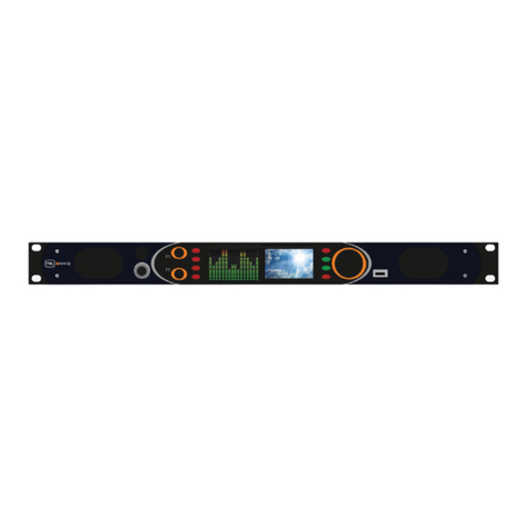
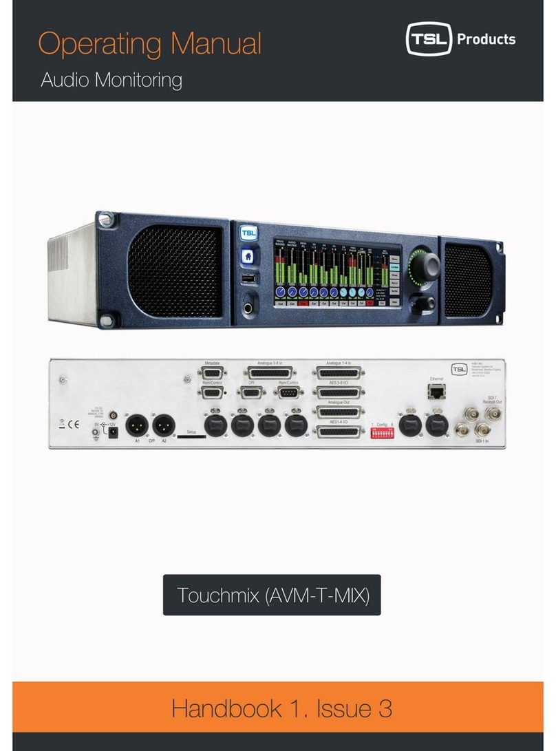
TSL AMU2-2MA User manual

AMU2-2MA MKIII0ISSUE 1
AMU2-2MA
AUDIO MONITORING
UNIT
HANDBOOK
Television Systems Limited.
Vanwall Road, Maidenhead, Berkshire, SL6 4UB
Telephone +44 (0)1628 676200, FAX +44 (0)1628 676299

AMU2-2MA MKIII1ISSUE 1

AMU2-2MA MKIII2ISSUE 1
EC DECLARATION OF CONFORMITY
Application of Council Directives Nos:
EC Low Voltage Directive (73/23/EEC)(OJ L76 26.3.73)(LVD).
Amendment: (93/68/EEC) (OJ L220 30.8.93).
Conformity Standards Declared:
EN 60950
EMC Directive: 89/336/EEC, Amended 92/31/EEC.
Conformity Standards Declared:
EN 50081-1: 1992-EMC-Generic Emissions, Part 1.
EN 50082-1: 1997-EMC-Generic Immunity, Part 1.
EN61000-3-2: 1995-Current Harmonic Emissions.
EN61000-3-3: 1995-Voltage Fluctuations & Flicker.
Manufacturer’s Name: Television Systems Ltd
Manufacturer’s Address: Vanwall Road
Maidenhead SL6 4UB
England
United Kingdom
Type of Equipment: Audio Video Monitoring Unit
Model No: AMU2-2MA MKIII
Part Number: TSLP-AMU2-2MA MKIII
Date CE Mark Affixed: 15/11/99
I, the undersigned, declare that the equipment specified above conforms to the
quoted Directives and Standards.
Place: Maidenhead, England Signature:
Date: Print: R CHAMBERS
Position: PRODUCT MANAGER

AMU2-2MA MKIII3ISSUE 1

AMU2-2MA MKIII4ISSUE 1
SAFETY
Installation.
Unless otherwise stated TSL equipment may be installed at any angle or position
within an operating temperature range of 5?-30?C .
All TSL equipment conforms to the EC Low Voltage Directive:
EC Low Voltage Directive (73/23/EEC)(OJ L76 26.3.73)(LVD).
Amendment: (93/68/EEC) (OJ L220 30.8.93).
In all cases the frame of the equipment must be earthed on installation.
The earth pin on the IEC mains inlet connector is connected to the metal frame of the
equipment, to 0 volts on the internal DC PSU and to signal ground, unless otherwise
stated. All metal panels are bonded together.
Check that the voltage selector setting (if fitted) and the fuse rating is correct for the
local mains supply.
WARRANTY, MAINTENANCE AND REPAIR
All TSL equipment is guaranteed for one year from the date of delivery to the
customer’s premises. If the equipment is to be stored for a significant period, please
contact TSL concerning a possible extended warranty period.
Failure during warranty
If any TSL product should fail or become faulty within the warranty period, first please
check the PSU fuses.
All maintenance work must be carried out by trained and competent personnel.
If equipment has to be returned to TSL for repair or re-alignment, please observe the
following overleaf:

AMU2-2MA MKIII5ISSUE 1

AMU2-2MA MKIII6ISSUE 1
TSL Returns Procedure
Please telephone +44 (0)1628 676200 (Fax: +44 (0)1682 676299) and ask for
Sales who will provide a Returns Number. This will enable us to track the unit
effectively and will provide some information prior to the unit arriving.
For each item, this unique Returns Number must be included with the Fault Report
sent with the unit.
A contact name and telephone number are also required with the Fault Report sent
with the unit.
Fault report details required.
?Company:
?Name:
?Address:
?Contact Name:
?Telephone No:
?Returns Number:
?Symptoms of the fault (to include switchsetting positions, input signals etc):
Packing
Please ensure that the unit is well packed as all mechanical damage is chargeable.
TSL recommends that you insure your equipment for transit damage.
The original packaging, when available, should always be used when returning
equipment..
If returned equipment is received in a damaged condition, the damage
should be reported both to TSL and the carrier immediately.
YEAR 2000 CONFORMITY REQUIREMENTS
This product conforms to the following rules:
Rule 1 No value for the current date will cause any interruption in operation.
Rule 2 Date based functionality will behave consistently for dates prior to, during
and after the Year 2000.
Rule 3 In all interfaces and data storage, the century in any date is specified either
explicitly or by unambiguous algorithms or by inferencing rules.
Rule 4 The Year 2000 is recognised as a leap year.

AMU2-2MA MKIII7ISSUE 1
Contents
1.0 Introduction
2.0 Front Panel Controls
2.1 Input and Meter Selection Buttons
2.2 Output Switching
3.0 AMP-2 Facilities
4.0 Pin-out Details
4.1 Analogue XLR Connectors
4.2 Audio Input Connector -D50 Socket Pinouts
4.3 Audio Input Connector -D50 Socket
4.4 Audio Output Connector -D25 Plug
4.5 Control Connector -D9 Socket
4.6 External Connector -D15 Plug
5.0 LS Output
6.0 AMU Alignment Procedure
6.1 Initial Set-Up
6.2 Audio Alignment AMP-2
6.3 PPM Calibration Procedure
6.4 VU Calibration Procedure
6.5 Bargraph Calibration Procedure
7.0 General Notes

AMU2-2MA MKIII8ISSUE 1

AMU2-2MA MKIII9ISSUE 1
AMU2-2MA MKIIIAUDIO MONITORING UNIT
1.0 Introduction
The AMU2-2MA MKIII is a 2RU x 300mm deep Audio Monitoring Unit with Sifam
PPM or VU meters.
The following features are standard:
?Two Sifam 32 style meters.
?Eight switch selectable stereo analogue inputs.
?Audio-present indication.
?Phase correlation indication.
?Phase reverse switch.
?Out-of-phase error indication.
?M and S PPM Switching.
?Optional additive output switch selection.
?Two x 18 Watt RMS into 4?loudspeaker amplifiers.
?Headphone outputs with LS muting.
?Fixed and variable stereo line outputs.
?RS422 remote control option.
?Legendable buttons
2.0 Front Panel Controls
2.1 Input and Meter Selection Buttons
1 –8 Analogue I/Ps. A1 (Left Channel) is fed to the left meter
and A2 (Right Channel) is fed to the right meter.
M/S Displays the MIX (mono) signal on the left meter and the
SEPARATION (difference) on the right meter of the
selected Input.
Ø Rev Momentary phase reverse between A1 and A2.

AMU2-2MA MKIII10 ISSUE 1
2.2 Output Switching
A1/A2 These buttons select either:
-the Analogue Left or Right signals of the metered Input.
DIM Approximately 16dB of attenuation is switched into the
audio path
CUT/MUTE The front panel button CUT(s) the signal to all O/Ps.
Remote Mute of either or both of the LS O/Ps and
Variable Line O/Ps are possible via a rear connector. A
ground is required on the appropriate pin to activate the
MUTE condition.
VOLUME The Headphones O/P and the Variable Line O/P may be
varied.

AMU2-2MA MKIII11 ISSUE 1
3.0 AMP-2 Facilities
This card provides all of the analogue processing.

AMU2-2MA MKIII12 ISSUE 1
4.0 Pin-out Details
4.1 Analogue XLR Connectors
XLRS PIN FUNCTION
ANALOGUE 1 1GND
ANALOGUE 1 21 IN+
ANALOGUE 1 31 IN-
ANALOGUE 2 1GND
ANALOGUE 2 22 IN+
ANALOGUE 2 32 IN-
ANALOGUE 3 1GND
ANALOGUE 3 23 IN+
ANALOGUE 3 33 IN-
ANALOGUE 4 1GND
ANALOGUE 4 24 IN+
ANALOGUE 4 34 IN-
ANALOGUE OUT 1GND
ANALOGUE OUT 2OUT+
ANALOGUE OUT 3OUT-

AMU2-2MA MKIII13 ISSUE 1
4.2 Audio Input Connector -D50 Socket Pinouts
D 50 SOCKET
ON AMU AUDIO
INPUTS FUNCTION D 50 SOCKET
ON AMU AUDIO
INPUTS FUNCTION
PIN NO LEFT PIN NO RIGHT
1I/P1 A1 SCREEN 9I/P1 A2 SCREEN
18 I/P1 A1 -26 I/P1 A2 -
34 I/P1 A1 +42 I/P1 A2 +
2I/P2 A1 +10 I/P2 A2 +
19 I/P2 A1 -27 I/P2 A2 -
35 I/P2 A1 SCREEN 43 I/P2 A2 SCREEN
3I/P3 A1 SCREEN 11 I/P3 A2 SCREEN
20 I/P3 A1 -28 I/P3 A2 -
36 I/P3 A1 +44 I/P3 A2 +
4I/P4 A1 +12 I/P4 A2 +
21 I/P4 A1 -29 I/P4 A2 -
37 I/P4 A1 SCREEN 45 I/P4 A2 SCREEN
5I/P5 A1 SCREEN 13 I/P5 A2 SCREEN
22 I/P5 A1 -30 I/P5 A2 -
38 I/P5 A1 +46 I/P5 A2 +
6I/P6 A1 +14 I/P6 A2 +
23 I/P6 A1 -31 I/P6 A2 -
39 I/P6 A1 SCREEN 47 I/P6 A2 SCREEN
7I/P7 A1 SCREEN 15 I/P7 A2 SCREEN
24 I/P7 A1 -32 I/P7 A2 -
40 I/P7 A1 +48 I/P7 A2 +
8I/P8 A1 +16 I/P8 A2 +
25 I/P8 A1 -33 I/P8 A2 -
41 I/P8 A1 SCREEN 49 I/P8 A2 SCREEN
17 SCREEN
50 SCREEN

AMU2-2MA MKIII14 ISSUE 1
4.3 Audio Input Connector -D50 Socket

AMU2-2MA MKIII15 ISSUE 1
4.4 Audio Output Connector -D25 Plug
D 25 PLUG
ON AMU AUDIO OUTPUTS
PIN NO FUNCTION
1A1+ Fixed
14 SCREEN
2A1-Fixed
15 A2+ FIXED
3SCREEN
16 A2-FIXED
4A3+ FIXED
17 SCREEN
5A3-FIXED
18 A4+ FIXED
6SCREEN
19 A4-FIXED
7A1+ VARIABLE
20 SCREEN
8A1-VARIABLE
21 A2+ VARIABLE
9SCREEN
22 A2-VARIABLE
23,12,13 SCREEN
4.5 Control Connector -D9 Socket
This is wired for RS422.
D9 CONTROL
10V
60V
2TX-
7TX+
3RX+
8RX-
40V
90V
5N/C

AMU2-2MA MKIII16 ISSUE 1
4.6 Audio Input Connector -D50 Socket
External Connector –D15 Plug
D15 EXTERNAL
PIN FUNCTION
1Mute 1
2Mute 2
3GPI-1
4GPI-2
5N/C
6N/C
7N/C
8N/C
9N/C
10 N/C
11 N/C
12 N/C
13 N/C
14 +5V
15 0V
5.0
LS Output -LSA-4/2 card
The loudspeaker amplifier uses a bridged circuit producing high output power.
Therefore, neither output terminal may be connected to ground.
6.0 AMU Alignment Procedure
This procedure assumes that the user is familiar with precision audio equipment
alignment. All model variants are covered here so the user will understand the
function of the various controls.
It is recommended that an exchange card is obtained from TSL in the event of a fault.
Due to the complexity of these circuit cards TSL use a custom jig for accurate
alignment.

AMU2-2MA MKIII17 ISSUE 1
6.1 Initial Set-Up
Connect 1khz Tone @ 0dB to Analogue I/P 1 L & R.
Set front panel switches to Analogue I/P 1, check for audio presence indication on
front panel LEDs and deflection on both meters.
6.2 Audio Alignment AMP-2
The board is set for unity gain.
Place the AMP-2 PCB on an extender card.
PR1 is set for the LH A1 channel 0dB O/P probe pins C10/C11-balanced.
PR2 is set for the RH A2 channel 0dB O/P probe pins C12/C13–balanced.
PR5 is set for 0db for the fixed A3 channel probe pins C14/C15–balanced.
PR6 is set for 0dB for the fixed A4 channel probe pins C16/C17–balanced.
PR3 is set for 0dB for the S signal probe pin C1.
PR4 is set for 0dB for the M signal probe pin C1.
PR7 is the LH PPM drive output and is set for 0dB probe pin C24.
PR8 is the RH PPM drive signal and is set for 0dB probe pin C25.
6.3 PPM Calibration Procedure
Alignment ACB Card
VR1 sets the +12dB point for the LH PPM Meter
VR2 sets the +12dB point for the RH PPM meter
VR4 sets the–12dB point for the LH PPM Meter
VR5 sets the–12dB point for the RH PPM Meter
Repeat the process for accurate tracking
6.4 VU Calibration Procedure
The drives for the VU meters are taken from the AMP-
2 card pins
C24 and C25, left and right respectively
With 0dBu or desired reference signal injected into the Analogue 1 I/P, adjust the
variable resistor on the meter PCB for -4 VU. (0VU = +4dBu).
6.5 Bargraph Calibration Procedure
The drives for the RTW bargraph meters are taken from the AMP-
2 card pins
C24 and C25, left and right respectively

AMU2-2MA MKIII18 ISSUE 1
7.0 General Notes
1. Please note that some American equipment has the function of the
XLR pins 2 & 3 reversed.
TSL product is wired to the European standard

AMU2-2MA MKIII19 ISSUE 1
8.0 AMU2-2MA Mk3 Technical Specifications
Power Supply
Supply Voltage 90 -250V AC @ 50Hz/60Hz +/-10%
Power Consumption 150 VA Max.
Physical Dimensions
Height 88mm (2RU)
Width 483mm (19”)
Depth 300mm
Weight 4800gm
Inputs 1, 2, 3 & 4.
Connector Type XLR Female 3 pin. Pin 1 Gnd, Pin 2 hot, Pin 3 cold.
Signal Balanced line level audio.
Frequency Response 30Hz to 25kHz
Impedance >20k?
Inputs 1 -8
Connector Type D50.
XLR Inputs 1, 2 & 3. In parallel
Signal Balanced line level audio.
Frequency Response 30Hz to 25kHz ±1dB
Impedance >20k?
Line Output.
Connector XLR 3 pin Male
Impedance 50?
Output Levels Through level control with 0dB gain.
Connector D25
Impedance >10k?
Output Levels Fixed and variable
Headphone Output.
Connector Stereo Jack socket type A
Impedance 50?
Output Levels Through level control with 0dB gain.
Loudspeaker Outputs.
Connectors 4mm Binding Posts
Output rating Max 30W RMS /Ch into 4?,
Table of contents
Other TSL Speakers System manuals

