ZIP CHAIN LIFTER
FEATURES
Comparison with
other devices
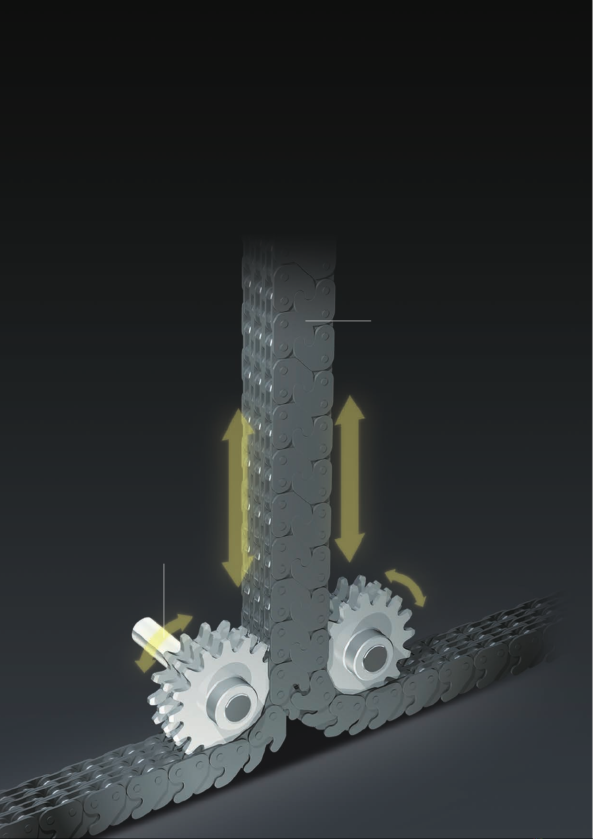
ZIP CHAIN LIFTER provides an innovative table lifter that directly transmits lifting thrust through ZIP CHAIN.
It operates 3 to 10 times faster than hydraulic lifters and supports high-frequency operation, which provides energy
savings as high as 50%.
With ZIP CHAIN LIFTER, the mass and thrust of the lifting
mechanism is supported directly by ZIP CHAIN, preventing
excessive force from being applied to the scissor arm
hinges, rollers, and bearings.
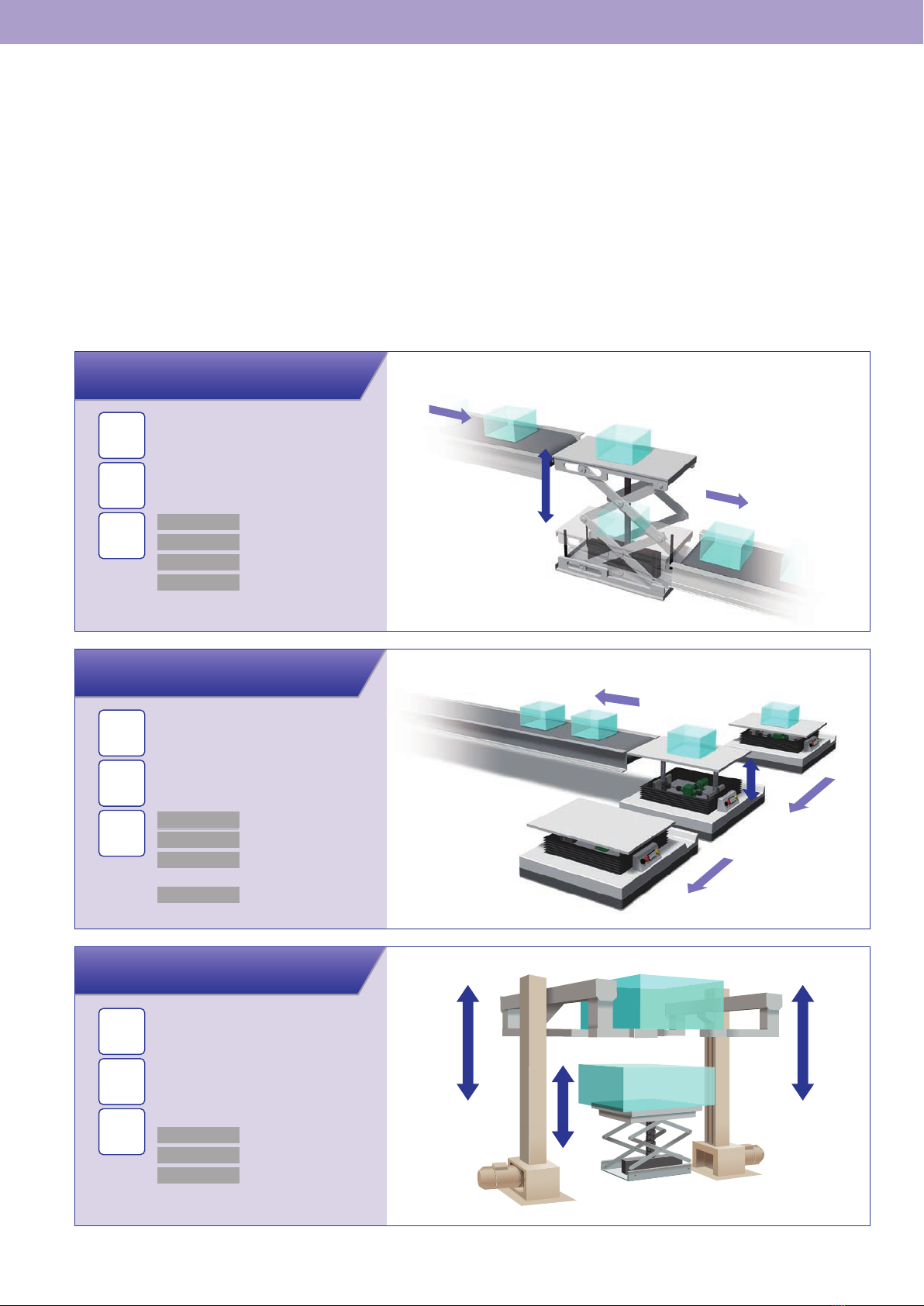
When lifting from the lowest
position, electric and hydraulic
cylinders push the lifter in a
diagonal direction and require a
large amount of power (1/sin
θ
times the lifting thrust).
Standard 1,000kg ZIP CHAIN LIFTER
COMPARISON WITH OTHER LIFTING METHODS
●Exceptional durability
ZIP CHAIN pushes the top plate directly, ensuring the motor
torque is transmitted efciently.
●Efficient transmission drive
ZIP CHAIN LIFTER Electric and hydraulic lifters
Ex.: At
θ
= 10°,
a thrust of 5.8 times the thrust force is required.
Standard 1,000kg lifting weight models in two different speeds.
Lifting weight
●Specications
Stroke
Speed with three-phase motor
Speed with servomotor
●Features
Operation cycle
Stopping accuracy
Expected life
1,000 kg
±1 mm
13.5 seconds
1,000 mm
5.5 m/min 11
m/min
19 m/min
(Single-stage pantograph) 1,600 mm
(Dual-stage pantograph)
More than
1
million
cycles
Speed
ZIP CHAIN LIFTER
Max. 100 m/min
good good good good
poor
poor
poor
poor
poor
poorpoor
good
Continuous operation
Oil temperature rise
Intermittent operation only
With servomotor
With servomotor
Difculty with intermediate stops
More than 1 million complete round trips
100,000 round trips
100,000 round trips
Max. 15 m/min
Max. 15 m/min
Electric screw-jack lifter
Hydraulic lifters
High frequency Stopping accuracy Expected life
Speed
ZIP CHAIN LIFTER achieves high-
speed operation at a maximum lifting
speed of 100m/min. This lifter works
through a mechanism that directly
pushes up the lift table at a stable
speed in proportion to motor rpm,
enabling lifting operation at a constant
speed. Synchronized operation of
multiple lifters is also possible.
●ZIP CHAIN LIFTER
It maintains a stable speed
through the entire stroke range.
The speed varies throughout the stroke.
It slows down in the middle.
●Hydraulic lifter
Lifting stroke
Lifting speed
Lifting stroke
Lifting speed
High-frequency operation
In the case of a hydraulic lifter, it
is necessary to increase the
tank capacity of hydraulic units
during high-frequency
operation. Since ZIP CHAIN
LIFTER is an electric
high-speed lifter, there is no
tank and high-frequency
operation is possible.
Supports high-speed operation
such as continuous lifting at a
rate of one lift cycle per minute
thanks to its efcient operation.
Expected life
ZIP CHAIN LIFTER has a
mechanism that directly pushes
the lift table, which places a
smaller load on the
hinges/rollers and enables
longer life (over one million
strokes).
4