Wessex lifts LIBERTY OPEN User manual

LIBERTY OPEN
OPERATOR & MAINTENANCE (O&M) MANUAL
Wessex Lift Co Ltd
Budds Lane,
Romsey,
Hampshire,
SO51 OHA, UK
OP00 7100, Revision A
October 2013

Liberty Open - Operator & Maintenance Manual
©Copyright 2013
Wessex Lift Co Ltd
All Rights Reserved
Except as expressly provided below, no part of this manual (which are the original instructions) may be
reproduced, copied, transmitted, disseminated, downloaded or stored in any storage medium, for any purpose
without the express prior written consent of Wessex. Wessex hereby grants permission to download a single copy
of this manual and of any revision to this manual onto a hard drive or other electronic storage medium to be
reviewed and to print one copy of this manual or of any revision hereto, provided that such electronic or printed
copy of this manual or revision must contain the complete text of this copyright notice and provided further that
any unauthorised commercial distribution of this manual or any revision hereto is strictly prohibited.
Information in this document is subject to change without notice. Wessex reserves the right to change or improve
its products and to make changes in the content without obligation to notify any person or organisation of such
changes or improvements
Wessex Lift Co Ltd
Budds Lane,
Romsey, SO51 OHA, UK
Tel. (+44) 01794 830303
Fax. (+44) 01794 521621
Web site address: www.wessexlifts.co.uk
RECORD OF REVISIONS
Revision Revision
Date
Description ECO
A
22/10/2013
Initial Release
1485
B
21/03/2017
Updated company logo
1584
OP00 7100_A.doc
Page 2of 34

Liberty Open - Operator & Maintenance Manual
Contents
1. Introduction…………………………………………………………………………………………………… 4
2. Safety Precautions……………………………………………………………………………………….... 5
2.1. General………………………………………………………………………………………………………... 5
2.2. Prohibited use……………………………………………………………………………………………… 5
2.3. WARNING – Overload………………………………………………………………………………….. 5
2.4. Repair and maintenance……………………………………………………………………………… 5
2.5. WARNING – Risk of crushing………………………………………………………………………… 5
2.6. Safety actions prior to working on the platform lift……………………………………... 6
2.7. Safety precautions when working under the platform…………………………………. 6
3. Standard Features…………………………………………………………………………………………… 7
3.1. Finish…………………………………………………………………………………………………………… 7
3.2. Standards & Compliance……………………………………………………………………………… 7
3.3. Safety Gear………………………………………………………………………………………………….. 7
3.4. Platform Sizes……………………………………………………………………………………………… 7
3.5. Application………………………………………………………………………………………………….. 7
3.6. Travel Speed……………………………………………………………………………………………….. 7
3.7. Safe Working Load (SWL)……………………………………………………………………………. 7
3.8. Manual Lowering ………………………………………………………………………………… 7
3.9. Safety Features…………………………………………………………………………………………… 7
3.10. Lift Enclosure……………………………………………………………………………………………. 7
4. Operating Instructions…………………………………………………………………………………… 8
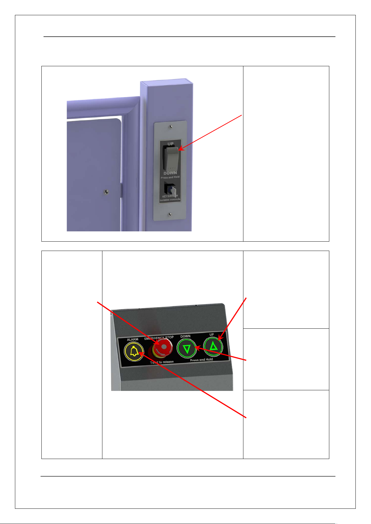
4.1. Call Stations – Internal Standard Controls………………………………………………….. 8
4.2. In-Car Internal Standard Controls (2-Stop)…………………………………………………. 8
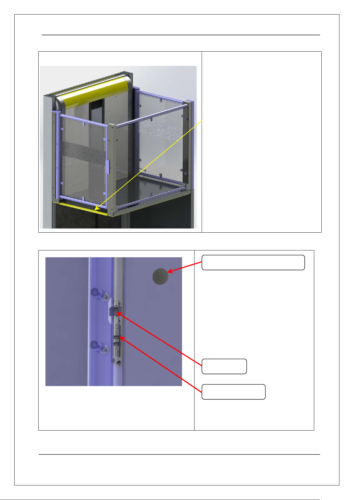
4.3. Sensitive Safety devices – ‘Safety Edges’……………………………………………………. 9
4.4. Gate Interlocks………………………………………………………………………………............. 9
4.5. Operation of the Platform lift (Overview)…………………………………………………… 10
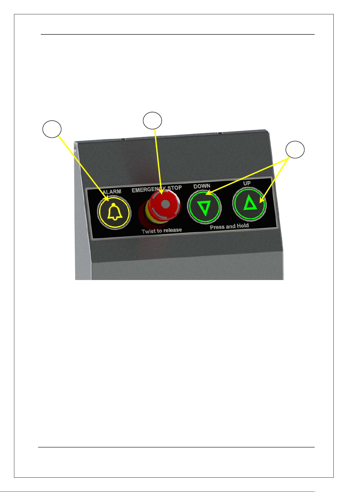
4.5.1. The Control Panel…………………………………………………………………… 10
4.5.2. Principle of Operation………………………………………………………………… 10
4.6. Calling the Lift…………………………………………………………………………………………….. 11
5. In the event of a failure……………………………………………………………………………….. 13
5.1. Raising the alarm………………………………………………………………………………………. 13
5.2. Emergency In-Car lowering……………………………………………………………………….. 13
5.3. Manual Lowering………………………………………………………………………………………. 13
5.4. Manual release of gates…………..............…………………………………………………… 15
6. Routine care and maintenance…………………………………………………………………….. 16
6.1. Domestic applications……………………………………………………………………………….. 16
6.2. Public access applications………………………………………………………………………….. 16
7. Operating difficulties and fault finding…………………………………………………………. 17
8. Emergency breakdown service……………………………………………………………………... 18
9. Service and Inspection………………………………………………………………………………….. 19
10. Lift technical specification………………………………………………………………………….. 23
11. Manufacturer information…………………………………………………………………………. 32
12. Manufacturer’s warranty…………………………………………………………………………… 33
EC Declaration of Conformity……………………………………………………………………………… 34
OP00 7100_A.doc
Page 3of 34

Liberty Open - Operator & Maintenance Manual
1. INTRODUCTION
Firstly thank you for buying this Wessex Open Platform Lift the "Liberty Open".
The Liberty Open lifting platform offers a wide range of options to suit most; if not all applications.
Employing the latest technologies in its design and operation we believe the Liberty Open is easy to use
and aesthetically pleasing on both internal and external applications. The simplicity of design will
provide for long service and reliability.
Wessex Lift Co Ltd has extensive experience (over 30 years) in providing products that aid mobility. We
consider ourselves one of the most experienced manufacturers in the market place today.
Our in-depth knowledge of associated building and electrical work and management expertise ensures
that the installation of all Wessex Equipment is completed with the minimum of disruption to you, the
end user.
This instruction manual has been written to help you become accustomed to your lift and we hope that
over the next few minutes you will: -
•Study and become familiar with the step by step instructions;
•Ensure that a nominated person is also familiar with the instructions, especially with the
operating procedures in the unlikely event of a breakdown.
•Keep this manual in a safe place for future reference together with the Test and Examination
Certificate and electrical wiring diagram.
•Ensure that any tools such as the Manual Gate Release key and Pump Enclosure door release
key are kept in a safe place for future use.
OP00 7100_A.doc
Page 4of 34

Liberty Open - Operator & Maintenance Manual
2. SAFETY PRECAUTIONS
2.1. General
Working on the platform lift may only be carried out by trained and competent persons.
2.2. Prohibited Use
•Never allow children to play with the lift and exercise care if children are playing in the vicinity
of the lift.
•Never jump or swing while the lift is in operation
•Watch out for loosely fitted clothes whilst travelling on the lift.
•Do not insert loose objects between the frame and the lift car or inside the frame.
•Stop the lift (release the push-button or press in the emergency stop) immediately on the
discovery of any danger.
•Do not remove parts of the lift and do not subject the lift to physical force or other damage.
•Signs with warning text and safety instructions must not be removed; covered or made illegible.
•Do not spray water on the lift or subject it to other liquid spillage.
•Do not use the lift it is faulty or functions abnormally.
•Pay attention to ensure that visible electrical components, for example, pushbuttons, cables,
and the like are not damaged.
•The lift must not be used for purposes other than those described in the manual.
•Material must not be transported unattended in the lift.
•Components higher than 2.2 metres must not be transported in the lift.
2.3. WARNING – Overload
Do not at any time exceed the Safe Working Load (SWL) of the lift, an overload is
indicated by a red L.E.D its position is lower left side of the label within the car.
2.4. Repair and Maintenance
Do not use, or attempt to use the lift if it is under maintenance or if you are instructed not to
do so by a qualified service engineer. Report any signs of damage/vandalism to Wessex Lift Co
Ltd or your appropriate service agent. Wessex Lift Co Ltd; do not encourage users to clean or
carry out any similar works that involves working under the platform or in areas that involves
the removal of panels or components of the lift. Any attempt to do so will invalidate the
warranty.
2.5. WARNING – Risk of Crushing
There is a risk of crushing when working under the platform. The installation or
service engineers should follow the instructions in the installation and service
manuals when carrying out any works below the platform. See section 2.7.
Under no circumstances should the operator of the lift be permitted to access the lift shaft
below the platform.
OP00 7100_A.doc
Page 5of 34

Liberty Open - Operator & Maintenance Manual
Fit and mechanically
lock Pit Prop in
Position!
2.6. Safety Actions prior to working on the platform lift.
The lift must always be disconnected from the mains supply
using the mains power switch before work or emergency
lowering is started.
Note: Consider lock and tag procedure if there is a risk of
interference by other parties.
Switch of the main power switch as follows:
1. Open the pump box enclosure and trip the MCB
2. Switch off the lift units main power switch lock and tag and place a warning sign prominently at
each platform lift entrance advising of work in progress.
2.7. Safety precautions when working under the platform
When working underneath the platform the lift must be run up a least
1 metre (or its maximum height) from the floor level.
The pit prop must now be positioned and fixed mechanically in place.
It is recommended that a safety helmet is worn to protect your head when working under the platform.
OP00 7100_A.doc
Page 6of 34

Liberty Open - Operator & Maintenance Manual
3. STANDARD FEATURES
3.1 Finish
To complement this product the paint finish on the OP Range, is a high quality durable powder coating.
The standard colour is from the interpon D (Akzo Nobel) Bleu Sable 700 but many other colours are
available as a cost option.
External models come with a 5 –year anti corrosion warranty as standard. (Subject to terms and
conditions)
3.2 Standards and Compliance
The lift is built in accordance to the essential health & Safety requirements (EHSR) of the European
Machinery Directive 2006/42/EC and is CE marked in accordance with this directive, the code of
practice BS 6440: 2011 is also applied to the product.
The product can also be made to comply with Part M of the UK building regulations by purchasing the
relevant optional extras.
3.3 Safety Gear
The use of rupture valves prevents the rapid descent of the lift in the event of a hydraulic hose or pump
failure.
3.4 Platform Sizes
•OP01 – 1460 x 800
•OP02 – 1460 x 900
•OP03 – 1460 x 1100
3.5 Application
The lift is suitable for internal or external applications
3.6 Travel Speed
The lift has a rated speed of 80mm/sec.
3.7 Safe Working Load
The Maximum Safe working load is 300kg (47 Stone)
3.8 Manual Lowering
In the event of a power failure the lift can be lowered to the ground floor by operating the in-car
emergency lowering facility or by operating the solenoid lowering valve on the pump unit.
3.9 Safety Features
Sensitive Safety devices (Safety Edges) on all leading edges of the platform and carrier frame
3.10 Lift enclosure
This product does not have a lift shaft enclosure, it uses a travelling cage type arrangement.
A full Technical specification can be found in Section 10 of this manual.
OP00 7100_A.doc
Page 7of 34

Liberty Open - Operator & Maintenance Manual
4. OPERATING INSTRUCTIONS - CONTROLS
4.1 Upper/Lower Landing Call Station (Standard Controls)
The Upper landing call
station is operated simply
by pressing and releasing
the rocker call switch.
The lift will automatically
travel to where you are.
(Picture left shows standard
call station with key switch
option - at upper level)
4.2 In Car Internal Standard Controls (2-Stops)
Emergency Stop
To stop the lift in
the event of an
emergency, press
the red
‘emergency stop’
button.
The button will
stay locked down.
The lift will not
work when the
stop button is in
this position.
To release, twist
the red button
clockwise.
(Picture above shows high spec raised tactile,
illuminated call buttons) In Car.
Up Direction – Press and
hold the green arrow to
make the lift move up.
(Note: If you release the
button the lift will stop).
Down Direction
– Press
and hold the green arrow to
make the lift move Down.
(Note: If you release the
button the lift will stop).
Alarm – Press and hold the
‘alarm button’ to sound the
alarm.
OP00 7100_A.doc
Page 8of 34

Liberty Open - Operator & Maintenance Manual
4.3 Sensitive Safety Devices – ‘Floating Platform
Floating Platform Safety Sensitive
Surface.
The underside of the platform has a
sensitive surface that triggers the lift to
stop should it encounter an obstacle in
the downward direction. This is shown in
Yellow in the picture (Left).
If the platform or carrier comes into
contact with an obstruction the lift will
stop. The lift can only be restarted once
the obstruction has been removed.
4.4 Gate Interlocks
Notes:
Latch Plate removed for clarity
Gate tube upright shown transparent
The lower level and Upper level gates are
fitted with an interlocking arrangement to
prevent un-controlled movement of the
carrier.
The platform lift will not move if the gate
is not fully latched and locked in place.
Lock/Latch
Interlock Contacts
Manual Gate Release Access Hole
OP00 7100_A.doc
Page 9of 34

Liberty Open - Operator & Maintenance Manual
4.5 Operation of the Platform lift (Overview)
4.5.1 - The control panel
The lift car is equipped with large, easy to use control buttons.
The control panel contains an alarm button (Item 2), and Emergency stop button (Item
3) and directional landing buttons (Item 4).
4.5.2 – Principle of Operation
The lift is designed and complies to the legal European directive 2006/42/EC and is
intended to operate as follows: -
The in car controls are of constant pressure i.e. the buttons must be kept depressed
throughout the travel. If released, the platform lift will stop immediately. When the
platform lift reaches the correct landing, it will stop automatically.
The in car control buttons take priority over the landing call stations; i.e. the landing call
stations will not work if someone is travelling at the same time.
The landing call station buttons are of one touch operation i.e. to call the lift simply
press and release the ‘CALL’ button to call the lift.
The landing controls can be altered upon request to suit Part M of the building
regulations so that they are also of the hold to run type.
2
3
4
OP00 7100_A.doc
Page 10 of 34

Liberty Open - Operator & Maintenance Manual
4.6 - Calling the Lift.
The Open platform lift is designed to service 2 landings, (Ground floor & 1st Floor), however,
calling the lift from any landing is essentially the same.
•If the platform is at the landing you are calling the lift from, then you simply just need to
press the call station button; an audible tone will sound at which point either the Gate
will open automatically or you will be able to open the gate manually and enter the
lift.
•If the platform is not at your landing then it will need to travel from its current landing
position to the landing that you are calling the lift from. Again simply press the call
station button. The platform will then travel to your landing level; you will then be able
to enter the lift. Gates will open automatically or manually depending on the options
selected on purchasing the lift.
Entering & Exiting the Lift.
The lift can be configured to allow the user to enter and exit the lift without the need to
reposition their wheelchair or other mobility device. You can simply enter the lift, and exit in
the same direction. A robust handle is provided so that the user can pull them self into the lift
car.
Closing the Gate.
Automatically operated Gates will close after a short time has elapsed. To re-open the Gates if
necessary press the call button for the floor where you currently are. On manually operated
Gates you simply need to ensure that the Gate latches shut.
Travelling to the required level.
Once the Gates have closed, the lift will now be permitted to travel to the required level. You
will note that the controls operate only by a ‘constant pressure’, i.e. as soon as you remove
your finger from any directional button the lift will stop. This is to allow the user to change
his/her mind and alter the direction of intended travel.
OP00 7100_A.doc
Page 11 of 34

Liberty Open - Operator & Maintenance Manual
Changing Direction of Travel.
If you wish to return to the level you have departed from (mid travel), simply remove your
finger from the in-car directional control button, wait 3 seconds and then select the new
direction of travel button. The lift will then move in the new direction. Alternatively the
original direction of travel can be maintained if desired.
Note: after releasing any control button there is a 3 second delay before allowing the user to
operate any other function.
OP00 7100_A.doc
Page 12 of 34

Liberty Open - Operator & Maintenance Manual
5. IN THE EVENT OF A FAILURE.
5.1 Raising the alarm.
In order for a trapped person to be able to call for help with an operating failure; the lift has
been equipped with an alarm facility. When the alarm button is depressed the emergency
signal is sounded. The alarm is powered by the battery backed facility.
5.2 Emergency In-Car lowering
In the event of a power failure which results in the user being trapped between floors, the lift
can be lowered to the floor that is the nominated exit point for the building. Emergency
lowering is achieved by pressing the down direction button which will be illuminated at point of
power failure.
In Car Emergency Lowering – Power
Failure
The lift incorporates a facility that will
allow the lift to be lowered to the ground
floor in the event of a power failure.
1. In the event of a power failure, the
lower Green, directional arrow will
illuminate.
2. At this point the operator can press and
hold the Green Down Arrow to allow the
lift to travel to the ground floor.
Note: In the unlikely event of this feature
not working the lift can be lowered using
the emergency lowering valve on the
pump unit, which is contained in an
enclosure.
5.3 Manual lowering.
In the event of a mains power and battery failure, the lift can be lowered to the ground floor by
operating the emergency-lowering solenoid valve located in the control box.
WARNING! Ensure that the control box is isolated from the mains supply before
opening. After using the emergency lowering valve, shut and lock the control box
before reconnecting the mains supply.
OP00 7100_A.doc
Page 13 of 34

Liberty Open - Operator & Maintenance Manual
Emergency Lowering – Using Pump
Lowering Valve.
1. using the Pump box Release key
(Provided) open the Enclosure door. Twist
key approximately ¼ turn and pull the
door open.
Note: It is recommended you keep the
release key in a convenient place in case of
an emergency.
2. Pull the red solenoid knob and the lift
will lower towards the ground, releasing
the knob will stop the platforms descent.
When the platform has reached the lower
floor level the Gate can be opened
manually.
WARNING! The safety devices
will not work when manually
lowering the lift. Ensure that any
obstructions are removed and that the
user is aware of the process.
OP00 7100_A.doc
Page 14 of 34

Liberty Open - Operator & Maintenance Manual
5.4 Manual Release of Gate
Manual Release of Gates
WARNING! Ensure that the lift
is at the lower level before
manually opening the Gate.
Remove the rubber grommet on the Gate
lock infill.
Align and insert the gate release key
provided,
Twist approximately ¼ turn and pull the
Gate open.
Note: It is recommended you keep the
gate release key in a convenient place in
case of an emergency.
Replace the grommet on completion.
OP00 7100_A.doc
Page 15 of 34

Liberty Open - Operator & Maintenance Manual
6. ROUTINE CARE & MAINTENANCE
6.1 Domestic Applications
Before cleaning your Liberty Open platform lift, please remember to switch off the unit at the
mains supply switch, adjacent to the control box.
Cleaning of the carriage area of the lift can be carried out using a variety of household cleaners,
we recommend that you remove any debris that has built up such as litter, leaves etc before
cleaning the main structure of the lift.
The surfaces of the lift can be cleaned with a damp (not wet) cloth and a detergent such as a
household washing up liquid. Any glazing panels can be cleaned using a suitable glass cleaner.
Note:Wessex in no way encourages private users to use ladders to clean the exterior of the lift
or the interior panels by balancing ladders on the platform.
If you wish your lift to be cleaned we recommend that you use a 3rd party contractor or contact
Wessex Lift Co Ltd for further assistance.
Wessex Lift Co Ltd recommends that your lift is service at 6 monthly intervals at which point
any maintenance requirements will be carried out.
6.2 Public Access Applications
Lifts that are installed in Public access applications are under the care of either attendants or
site service personnel. Any problems with the running and operation of the lift should be
reported directly to these bodies, who will arrange for the necessary actions to be instigated.
In most cases the fault will be reported either to Wessex Lift Co Ltd or the installation and
servicing agent responsible for the installation of the Liberty Open product.
OP00 7100_A.doc
Page 16 of 34

Liberty Open - Operator & Maintenance Manual
7. OPERATING DIFFICULTIES & FAULT – FINDING.
Incorrect operation of the equipment can often be misinterpreted for faults or malfunctions
with the lift. If you believe that there is a problem please first check the points below.
If the problem cannot be solved after carrying out these checks, then the lift must be switched
off and isolated from the mains electricity supply. To do this simply switch off the mains
electricity spur adjacent to the lift.
You should then contact your designated company responsible for repair and maintenance of
the lift.
Table 7.1 – Faultfinding Procedure
SYMPTOM CHECK
The lift will not operate - Ensure that the Gates are closed and interlocked.
- Ensure that the mains power is turned on.
- Ensure that the lift is not isolated via a key-switch; this
will result in the call buttons not being illuminated.
(check landing call stations and remote locking
devices, changing the position of any one key will
turn the lift off or on).
- Check that safety stop devices are not activated (E-Stop
button).
- Check that moving safety devices are not activated or
stuck in, check platform edges and top Carriage
safety edges).
- Ensure that the Residual Current Device (RCD)
switch & Miniature Circuit Breaker (MCB) are both
ON. Both are located within the control box.
Proceed as follows: -
•Ensure mains supply is OFF
•Unlock control box using special key
•RCD and MCB are situated at the top/back
of the cabinet.
•Switch both ON if tripped.
•Close and lock the gate.
•Turn mains supply back on.
OP00 7100_A.doc
Page 17 of 34

Liberty Open - Operator & Maintenance Manual
8. EMERGENCY BREAKDOWN SERVICE
The Wessex Customer Care Team is manned between 9:00am to 5:15pm, Monday to Friday
(except public holidays) and field service engineers normally operate during the same hours
An engineer will normally visit site within 24 hours (Monday to Friday) to attend to a
breakdown call, provided the equipment is covered by a warranty or the user (or any agency
responsible for the maintenance of the equipment) agrees that they will cover any costs
incurred.
Calls for assistance outside normal office hours will be handled by our emergency cover service
and every effort will be made to attend such calls within a reasonable time scale (i.e., within 24
hours) – however, there is no guarantee that an engineer can be available during these hours.
During normal office hour’s; telephone the emergency number indicated below and ask for The
Customer Care department. A member of staff will record details of your request and initiate
the necessary actions to resolve the problem.
Outside normal office hours telephone the emergency service number indicated below. The
operator will take details and pass this information to a duty engineer who will then contact
you by telephone to fully assess the problem and to offer a suitable level of technical assistance
to minimise the immediate difficulties being experienced. Where necessary and feasible the
duty engineer will make suitable arrangements to an engineer to attend site as soon as possible
to effect repairs.
The duty engineer is supported by a duty supervisor and duty manager to ensure that contact
with an engineer is always available outside normal office hours. The operator has facilities to
contact all of these people as appropriate.
For further information on breakdown cover and servicing please contact our Customer Care
Team.
Emergency Breakdown Service Telephone Number
+44 (0) 1794 830303
(24 Hour Service)
OP00 7100_A.doc
Page 18 of 34

Liberty Open - Operator & Maintenance Manual
9. SERVICE & INSPECTION
Your Liberty Open has been inspected and tested for quality and reliability. It should give you
many years of service as long as regular maintenance is correctly carried out. Failure to do this
could lead to unreliable or unsafe operation.
The Lift is guaranteed for 12 months, unless you have decided to purchase an extended
warranty at the same time as buying your unit. Alternatively, you may wish to establish a
maintenance agreement that will provide for routine servicing on a regular basis thereafter.
Wessex Lift Co Ltd recommends that the lift is checked and or Serviced every six months.
The lift is to be serviced in accordance to BS 6440: 2011 standard (Annex E), which includes,
but is not limited to the following: -
•Interlocking devices;
•Electrical safety devices;
•Earth continuity;
•Supporting and suspensions means for lifting (Hydraulic Rams);
•Driving unit, and or brakes;
•Devices for preventing free fall and descent with excessive speed, e.g. safety gear;
•Alarm system;
•Safety edges;
•Internal Surfaces (distances, surfaces and sharp edges);
•Guides and guide shoes or rollers;
•Lighting and any emergency lighting;
•Moving parts (Check for wear).
A certificate similar to that shown on the next page should be prepared and recorded in a log
to be retained on site. The examining authority should also retain a copy.
For all enquiries regarding service please contact
The Customer Care Team at:
Wessex Lift Co Ltd.
Budds Lane,
Romsey,
Hampshire,
SO51 0HA
Tel: +44(0) 1794 830 303
Fax: +44(0) 1794 512 621
OP00 7100_A.doc
Page 19 of 34

Liberty Open - Operator & Maintenance Manual
SERVICE & INSPECTION RECORD
Service Period
(Months)
Engineers Name
Company
Signature
Date
3
6
12 (1 Year)
18
24 (2 Years)
30
36 (3 Years)
42
48 (4 Years)
54
60 (5 Years)
66
72 (6 Years)
78
84 (7 Years)
90
96 (8 Years)
102
108 (9 Years)
114
120 (10 Years)
Circulation:
Copies for site log
Examining Authority
OP00 7100_A.doc
Page 20 of 34
This manual suits for next models
3
Table of contents