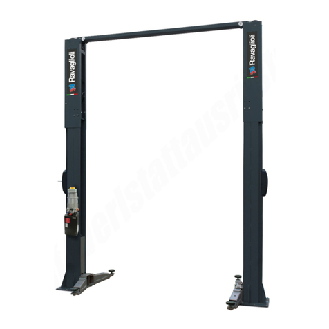
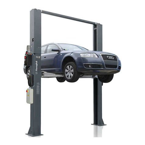
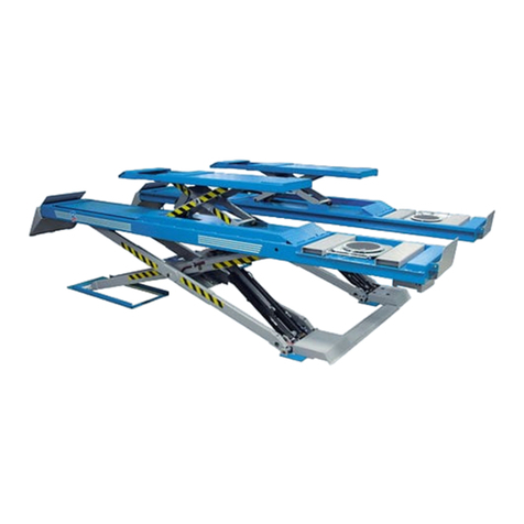
rav RAV540 User manual

0579-M070-0 Rev. n.4(01/2020)
SOLLEVATORE ELETTROIDRAULICO
ELECTRO-HYDRAULIC LIFT
ELEKTROHYDRAULISCHE HEBEBÜHNE
PONT ELEVATEUR ELECTRO-HYDRAULIQUE
ELEVADOR ELECTRO-HIDRÁULICO
RAV540 - RAV540 I
Redatto da Timage S.r.l.
0579-M070-0
Per eventuali chiarimenti interpellare il più vicino rivenditore oppure rivolgersi direttamente a:
Servizio assistenza tecnica: RAVAGLIOLI S.p.A - Via 1° Maggio, 3 - 40037 Pontecchio Marconi - Bologna Italia
For any further information please contact your nearest dealer or speak directly to:
Technical services: RAVAGLIOLI S.p.A. - Via 1° Maggio, 3 - 40037 Pontecchio Marconi - Bologna Italy
Im Zweifelsfall oder bei Rückfragen wenden Sie sich bitte an den nächsten Händler oder direkt an:
Kundendienst: RAVAGLIOLI S.p.A. - Via 1° Maggio 3, 40037 Pontecchio Marconi - Bologna - Italien
Pour tout renseignement complémentaire, s’adresser au distributeur le plus proche ou directement à:
Service Après-Vente: RAVAGLIOLI S.p.A. - via 1° Maggio 3 - 40037 - Pontecchio Marconi - Bologne - Italie
En caso de dudas, para eventuales aclaraciones, póngase en contacto con el distribuidor más próximo o diríjase
directamente a:
Servicio Post-Venta: RAVAGLIOLI S.p.A. - Via 1° Maggio, 3 - 40037 Pontecchio Marconi - Bologna - Italia
ITALIANO:ISTRUZIONIORIGINALI
ENGLISH: TRANSLATION OF THE ORIGINAL INSTRUCTIONS
DEUTSCH: ÜBERSETZUNG DER ORIGINALANLEITUNG
FRANÇAIS: TRADUCTION DES INSTRUCTIONS ORIGINALES
ESPAÑOL: TRADUCCIÓN DE LAS INSTRUCCIONES ORIGINALES

22 0579-M070-0
SIMBOLOGIA UTILIZZATA NEL MANUALE
SYMBOLS USED IN THE MANUAL
IN DER BETRIEBSANLEITUNG VERWENDETE ZEICHEN
SYMBOLES UTILISES DANS LA NOTICE
SIMBOLOGÍA UTILIZADA EN EL MANUAL
SIMBOLI SYMBOLS ZEICHEN SYMBOLES SÍMBOLOS
VIETATO! FORBIDDEN! VERBOTEN! INTERDIT! PROHIBIDO!
Indossare guanti da
lavoro Wear work gloves Der Arbeit ange-
messene Handschuhe
tragen
Porter des gants de
travail Llevar guantes de
trabajo
Calzare scarpe da
lavoro Wear work shoes Der Arbeit
angemessene Schuhe
tragen
Mettre des chaussures
de travail Usar zapatos de
trabajo
Indossare occhiali di
sicurezza Wear safety goggles Schutzbrille tragen Porter des lunettes de
protection Colocarse gafas de
seguridad
Indossare cuffie di
sicurezza Wear safety earcaps Schallschutzkapseln Porter un protecteur Colocarse gorras de
seguridad
Pericolo di scariche
elettriche Shock hazard Gefahr: elektrische
Entladungen Danger d'électrocution Peligro descargas
elèctricas
Attenzione carichi
sospesi Caution: hanging loads Achtung hängende
Lasten Attention: charges
suspendues Atenciòn cargas
suspendidas
Pericolo! Attenzione
agli organi meccanici
in movimento
Danger! Moving
mechanical parts Gefahrt! Bewegliche
mechanische Organe
Danger! Organes
mécaniques en
mouvement
Peligro! Partes
mecánicas en
movimiento
Pericolo di
schiacciamento Crushing danger Quetschgefahr Danger d'écrasement Peligros de
aplastamiento
Obbligo. Operazioni o
interventi da eseguire
obbligatoriamen-
te
Mandatory.
Operations or jobs to
be performed
compulsorily
Pflicht.
Obligatorisch
auszuführende
Arbeitsvorgänge oder
Eingriffe
Obligation.
Opérations ou
interventions
obligatoires
Obligación.
Operaciones o
intervenciones que hay
que realizar
obligatoriamente
Pericolo! Prestare
particolare attenzione. Danger! Be particulary
careful Gefahrt! Äusserste
Vorsicht ist geboten Danger! Faire trés
attention Peligro! Prestar
especial atención
Movimentazione con
carrello elevatore o
transpallet
Move with fork lift truck
or transpallet
Transport mit
Gabelstapler oder
Handgabelhub-
wagen
Déplacement avec
chariot élévateur ou
transpalette
Desplazamiento con
carretilla elevadora o
transpallet
Sollevamento dall'alto Lift from above Anheben von oben Levage par le haut Elevaciòn desde arriba

33
0579-M070-0
ATTENZIONE!
ATTENTION!
This manual forms an integral part of the product and must be kept together with the lift at all times. Store it in an easily
accessible and well-known place, to be consulted upon need. All operators must be allowed to read it. The manufacturer
disclaims any liability or responsability for any damage arising from non-compilance with the instructions provided in this
manual.
DasvorliegendeHandbuchisteinTeildes Produkts. Esmußüberdie gesamte StandzeitderHebebühnenhinweg aufbewahrt
werdenund diese immerbegleiten.Es istaneinem allgemein bekanntenOrtund leicht erreichbaraufzubewahren,damit jeder
imZweifelsfall darin nachschlagen kann. Allen Bediener, die mit demProduktzutunhaben, muß die Einsicht bzw. das Lesen
desHandbuchs ermöglicht werden. Jeder Schaden, der sichauseinemNichtbeachten der in diesem Handbuch angeführten
Angabenableitenläßt,könnendemHerstellernichtangelastetwerdenund befreiendie Herstellervon jeglicherVerantwortung.
ACHTUNG!
La présente notice est partie intégrante du produit; elle devra accompagner le pont élévateur pendant toute la durée de son
fonctionnement.Elle doit doncêtreconservée dans un endroitconnuet facilement accessible etêtreconsultée toutes lesfois
qu’undoute se présente.Touslesopérateurs qui utilisentlepontdoivent pouvoir lirelanotice.Aucune responsabilité nepeut
engagerle constructeur pourtoutdédommagement de préjudices découlantdunon-respect des instructions énoncéesdans
cettenotice.
ATTENTION!
¡ATENCIÓN!
Elpresente manual forma parte integrante del producto; tendrá que acompañaralelevadordurantetodo su funcionamiento.
Conservarlo por lo tanto en un sitio que conozcan todos, al que se pueda acceder con facilidad, y consultarlo cada vez que
surjandudas.
Todas las personas que utilizan el elevador tienen que poder leer el manual. Cualquier daño que derive del incumplimiento
de las indicaciones contenidas en el presente manual exime el constructor de toda responsabilidad.
Ilpresente manualecostituisce parteintegrantedel prodotto;dovràseguiretuttala vitaoperativadel sollevatore.Conservarlo,
quindi in un luogo noto e facilmente accessibile e consultarlo ogniqualvolta sorgano dubbi.
Tutti gli operatori al prodotto devono poter leggere il manuale. Ogni danno derivante dalla mancata osservanza delle
indicazionicontenute nel presente librettononsarà addebitabile al costruttoreedesimeil costruttore da ogniresponsabilità.
ZUSAMMENSETZUNG
DER ANLEITUNG
98 Seiten (inkl.
Deckblätter)
COMPOSITION DE LA
NOTICE
98 pages (pages de la
couverture incluses)
COMPOSICIÓN DEL
MANUAL
98 páginas (incluidas
las cubiertas)
COMPOSITION OF
MANUAL
98 pages (including
cover pages)
COMPOSIZIONE
DEL MANUALE
98 pagine (copertine
comprese)

44 0579-M070-0
INDICE
0. NORME GENERALI DI SICUREZZA ....................................... 6
0.1 Dispositivi di sicurezza ............................................................7
0.2 Indicazione dei rischi residui ...................................................9
1. DESTINAZIONE D'USO ......................................................... 11
2. MOVIMENTAZIONE E PREINSTALLAZIONE ...................... 15
3. DESCRIZIONE DEL SOLLEVATORE ................................... 17
3.1 Attitudine all'impiego .................................................................17
3.2 Caratteristiche tecniche principali ...........................................19
3.3 Comandi ...................................................................................20
3.4 Accessori a richiesta ...............................................................20
3.5 Accessori forniti .......................................................................20
4. INSTALLAZIONE .................................................................... 21
4.1 Verifica dei requisiti minimi richiesti dal luogo di
installazione..............................................................................21
4.2 Preparazionedell’area di installazione- RAV540 ......................23
4.3 Preparazionedell'area di installazione- RAV540I ....................25
4.4 Posizionamento delle pedane e collegamento dell'impianto in
posizionestandard - (RAV540)..................................................27
4.5 Posizionamento delle pedane e collegamento dell'impianto in
posizionestandard (RAV540I).................................................29
4.6 Allacciamento alla rete .............................................................31
4.7 Collegamento cavo alimentazione ..........................................31
4.8 Collegamento impianto pneumatico ........................................33
4.9 Montaggio cavi, collegamento CP, FC1 e FC2 - RAV540 ..........33
4.10 Montaggio CP e finecorsa FC1 e FC2 - (RAV540 I) ..................35
4.11 Sincronizzazionepedane ..........................................................35
4.12 Spurgo aria...............................................................................37
4.13 Fissaggio del sollevatore.........................................................38
4.14 Attivazione e registrazione delle sicurezze ...............................38
4.15 Verifica delle sicurezze .............................................................39
4.16 Montaggiorampinesu rampe ....................................................41
INDEX
0. GENERAL SAFETY PRECAUTIONS ....................................... 6
0.1 Safety devices .........................................................................7
0.2 Indication of outstanding risks.................................................9
1. PURPOSE OF THE MACHINE............................................... 11
2. PRE-INSTALLATION AND MOVEMENT .............................. 15
3. DESCRIPTION OF THE LIFT ................................................ 17
3.1 Preparation for use ..................................................................17
3.2 Main technical characteristics.................................................19
3.3 Controls....................................................................................20
3.4 Accessories on request ..........................................................20
3.5 Available accessories..............................................................20
4. INSTALLATION ...................................................................... 21
4.1 Checking the minimum requirements for the installation site .21
4.2 Preparing the installation area -RAV540 ..................................23
4.3 Preparing theinstallation area- RAV540 I.................................25
4.4 Positioning the footboards and connecting the system in the
standardposition-(RAV540)......................................................
27
4.5 Positioning the footboards and connecting the system in the
standardposition-(RAV540I) ...................................................29
4.6 Connecting to the mains ..........................................................31
4.7 Connecting the power cable....................................................31
4.8 Compressed air connection ....................................................33
4.9 Fitting the pawl release cable, connecting CP, FC1, FC2 -
RAV540 .....................................................................................33
4.10 Fitting the CP and limit switches FC1 and FC2 - RAV540I .......35
4.11 Synchronising the footboards .................................................35
4.12 Bleeding the air ........................................................................37
4.13 Fastening the lift .......................................................................38
4.14 Activating and adjusting the safety switches ............................38
INHALT
0. ALLGEMEINE SICHERHEITSVORSCHRIFTEN ..................... 6
0.1 Sicherheitsvorrichtungen ........................................................7
0.2 Hinweise zu den Restrisiken...................................................9
1. BESTIMMUNGSGEMÄSSE VERWENDUNG .......................11
2. TRANSPORT UND VORINSTALLATION ............................. 15
3. BESCHREIBUNG DER HEBEBÜHNE ..................................17
3.1 Betriebstüchtigkeit ...................................................................17
3.2 Technische Haupteigenschaften.............................................19
3.3 Steuerungen.............................................................................20
3.4 Zubehör auf Anfrage................................................................20
3.5 Geliefertes Zubehör.................................................................20
4. AUFSTELLUNG ......................................................................21
4.1 Kontrolle der Mindesterfordernissen für den Aufstellungsort.21
4.2 Vorbereitung der Aufstellungsfläche - RAV540 ........................23
4.3 Vorbereitung derAufstellungsfläche - RAV540 I ......................25
4.4 Positionierung der Fahrschienen und Anschluss der
HydraulikanlageinStandardposition -
(RAV 540)..................................................................................27
4.5 Positionierung der Fahrschienen und Anschluss der Hydraulikanlage
inStandardposition-(RAV540I) ...................................................29
4.6 Netzanschluss.........................................................................31
4.7 Versorgungskabelanschluss...................................................31
4.8 Pressluftanschluss ..................................................................33
4.9 Montage der Kabel,Anschluss CP, FC1, FC2 - RAV540 .........33
4.10
Montage CP und Endschalter FC1 und FC2 -(RAV540 I) .......
35
4.11 Fahrschienen-Gleichlaufregelung ...........................................35
4.12 Entlüftung .................................................................................37
4.13 Verdübelung der Hebebühne ...................................................38
4.14 Aktivierung und Einstellungder Sicherheitseinrichtungen .........38
4.15 KontrollederSicherheitseinrichtungen ......................................39
4.16 Montage derkleinen Heberampen .............................................41
SOMMAIRE
0. NORMES GENERALES DE SECURITE .................................. 6
0.1 Dispositifs de sécurité .............................................................7
0.2 Informations sur les risques résiduels ....................................9
1. DESTINATION D’USAGE ....................................................... 11
2. DEPLACEMENT ET PRE-INSTALLATION .......................... 15
3. DESCRIPTION DU PONT ELEVATEUR ............................... 17
3.1 Aptitude pour l’emploi ...............................................................17
3.2 Principales caractéristiques techniques .................................19
3.3 Commandes.............................................................................20
3.4 Accessoires sur demande ......................................................20
3.5 Accessoires disponibles .........................................................20
4. INSTALLATION ...................................................................... 21
4.1 Vérification des caractéristiques minimes requises pour la
zone d’installation....................................................................21
4.2 Préparationdelazoned’installation-RAV540 ...............................23
4.3 Préparationde la zoned’installation-RAV540I .............................25
4.4 Positionnement des chemins de roulement et connexion de
l‘installationdanslapositionstandard-(RAV540) ...........................27
4.5 Positionnement deschemins de roulement et connexionde
‘installationdanslapositionstandard-(RAV540I) .................................... 29
4.6 Connexion au réseau ..............................................................31
4.7 Connexion du câble d’alimentation ..........................................31
4.8 Connexion de l’installation pneumatique .................................33
4.9 Montage du câble de connexion CP, FC1, FC2 - RAV540 .......33
4.10 Montage du CP et des butées de fin de course FC1 et FC2
(RAV540 I).................................................................................35
4.11 Synchronisation deschemins de roulement..............................35
4.12 Purge de l’air ............................................................................37
4.13 Ancragedu pont élévateur ........................................................38
4.14 Actionnementet réglagedes sécurités .....................................38
4.15 Contrôle des sécurités ..............................................................39
ÍNDICE
0. NORMAS GENERALES DE SEGURIDAD ............................... 6
0.1 Dispositivos de seguridad .......................................................7
0.2 Indicaciones de los riesgos residuos .....................................9
1. DESTINACIÓN DE USO ........................................................ 11
2. DESPLAZAMIENTO Y PREINSTALACIÓN .......................... 15
3. DESCRIPCIÓN DEL ELEVADOR .......................................... 17
3.1 Aptitud para el empleo .............................................................17
3.2 Características técnicas principales ......................................19
3.3 Mandos ....................................................................................20
3.5 Accesorios en dotación ...........................................................20
4. INSTALACIÓN ........................................................................ 21
4.1 Comprobación de los requisitos mínimos requeridos para el
sitio de la instalación ................................................................21
4.2 Preparacióndeláreadeinstalación-RAV540.............................23
4.3 Preparacióndeláreadeinstalación-RAV540I...............................25
4.4 Colocación de las tarimas y conexión de la instalación en
posiciónestándar(RAV540) ......................................................27
4.5 Colocación de las tarimas y conexión de la instalación en
posiciónestándar (RAV540I)....................................................29
4.6 Conexión a la red..................................................................... 31
4.7 Conexión cable de alimentación............................................. 31
4.8 Conexión de la instalación neumática .....................................33
4.9 Montaje cable de conexión CP, FC1, FC2 - RAV540 ................33
4.10 Montaje CP y microinterruptor de tope FC1 y FC2
(RAV540 I).................................................................................35
4.11 Sincronización de las plataformas ..........................................35
4.12 Purga del aire ...........................................................................37
4.13 Sujeción del elevador...............................................................38
4.14 Activación y regulación de los dispositivos de seguridad ......... 38
4.15 Comprobaciónde los dispositivosde seguridad .......................39
4.16 Montaje rampas de subida en lasrampas.................................41

55
0579-M070-0
4.17 Registrazione livellamento rampine ........................................... 41

4.18 Montaggio supporto rampa - RAV540 I .....................................43
4.19 Fissaggio coperture, centralina - RAV540 ................................. 43
5. ISTRUZIONI PER L'USO DEL SOLLEVATORE ...................... 44
5.1 Uso improprio del sollevatore .................................................... 44
5.2 Uso di accessori ....................................................................... 44
5.3 Addestramento del personale preposto ..................................... 44
5.4 Precauzioni d'uso ......................................................................45
5.5 Identificazione dei comandi e loro funzione .............................. 47
6. SICUREZZA.............................................................................. 48
6.1 Procedura di emergenza ........................................................... 48
6.2 Sicurezze ..................................................................................49
7. MANUTENZIONE ..................................................................... 50
7.1 Cambio olio centralina ............................................................... 50
7.2 Pulizia elettrovalvole ................................................................. 50
7.3 Pulizia valvola regolatrice di portata.......................................... 51
7.4 Lubrificazione ............................................................................ 52
8. INCONVENIENTI ...................................................................... 53
9. ACCANTONAMENTO ............................................................... 58
10. ROTTAMAZIONE ...................................................................... 59
SCHEMA IMPIANTO ELETTRICO ........................................... 60
SCHEMA IMPIANTO OLEODINAMICO ................................... 62
SCHEMA IMPIANTO PNEUMATICO ....................................... 62
11. RICAMBI ................................................................................... 64
11.1 Come richiedere i ricambi .......................................................... 64
11.2 Indice tavole ricambi ................................................................. 64
12. VERIFICHE DI INSTALLAZIONE E PERIODICHE ............... 80
13. TARGHETTA DI IDENTIFICAZIONE .................................... 92
4.15 Checking the safety switches ................................................... 39
4.16 Assembling ramps .................................................................... 41
4.17 Adjusting the levelling of the ramps .......................................... 41
4.18 Fitting the ramp support - RAV540 I ........................................... 43
4.19 Securing covers, control unit - RAV540 ................................... 43
5. INSTRUCTIONS FOR USING THE LIFT .................................. 44
5.1 Improper use of the lift .............................................................. 44
5.2 Use of accessories ................................................................... 44
5.3 Training the machine-operating staff ......................................... 44
5.4 Important checks to be made ................................................... 45
5.5 Description and function of commands ..................................... 47
6. SAFETY.................................................................................... 48
6.1 Emergency procedures ............................................................. 48
6.2 Safety devices .......................................................................... 49
7. MAINTENANCE ........................................................................ 50
7.1 Changing the oil in the central unit ............................................ 50
7.2 Cleaning the solenoid valves ....................................................50
7.3 Cleaning the capacity regulator valve ....................................... 51
7.4 Lubrication ................................................................................. 52
8. PROBLEM ................................................................................ 54
9. STORAGE ................................................................................ 58
10. SCRAPPING ............................................................................. 59
WIRING DIAGRAM ................................................................... 60
DIAGRAM OF HYDRAULIC SYSTEM .................................... 62
DIAGRAM OF PNEUMATIC SYSTEM ..................................... 62
11. SPARE PARTS ......................................................................... 64
11.1 How to order spare parts ...........................................................64
11.2 Spare parts summary ................................................................64
12. INSTALLATION AND PERIODIC INSPECTIONS ................80
13. IDENTIFICATION PLATE ....................................................... 92
4.17 Einstellung für Rampennivellierung ........................................... 41
4.18 Montage der Rampenhalterung -RAV540 I ................................. 43
4.19 Befestigung derAbdeckungen, des Schaltschrankes
RAV540 ..................................................................................... 43
5. ANWEISUNGEN FÜR DIE BEDIENUNG DER HEBEBÜHNE ....... 44
5.1 Unsachgemässe Bedienung der Hebebühne ............................. 44
5.2 Gebrauch von Zubehörteilen ..................................................... 44
5.3 Schulung des Bedienerpersonals ..............................................44
5.4 Vorsichtsmassnahmen .............................................................. 45
5.5 Die Steuerungen und ihre Funktion ........................................... 47
6. SICHERHEIT ............................................................................48
6.1 Not-Aus-Verfahren ..................................................................... 48
6.2 Sicherheitseinrichtungen ........................................................... 49
7. WARTUNG ................................................................................ 50
7.1 Ölwechsel im Schaltschrank ..................................................... 50
7.2 Reinigung der Elektroventile ...................................................... 50
7.3 Reinigung des Stromventils ...................................................... 51
7.4 Schmierung ............................................................................... 52
8. BETRIEBSSTÖRUNGEN ......................................................... 55
9. EINLAGERUNG ........................................................................ 58
10. VERSCHROTTUNG .................................................................. 59
SCHALTPLAN ELEKTROANLAGE .......................................... 60
SCHALTPLAN ÖLDYNAMISCHE ANLAGE ............................. 62
SCHALTPLAN DRUCKLUFTANLAGE ..................................... 62
11. ERSATZTEILE ......................................................................... 64
11.1 Ersatzteilanforderung ................................................................ 64
11.2 Tafelverzeichnis ........................................................................ 64
12. KONTROLLEN DER ERSTINSTALLATION UND
REGELMÄSSIGE KONTROLLEN ........................................ 80
13. ERKENNUNGSSCHILD ......................................................... 92
4.16 Montage des rampes de montée ............................................... 41
4.17 Réglage du niveau des petites rampes d’accès ........................ 41
4.18 Montage du support de rampe - RAV540 I ................................ 43
4.19 Fixation des couvertures, de la centrale -RAV540 .................... 43
5. MODE D’EMPLOI DU PONT ELEVATEUR.............................. 44
5.1 Utilisation incorrecte du pont élévateur ..................................... 44
5.2 Utilisation d’accessoires ........................................................... 44
5.3 Formation du personnel préposé ............................................... 44
5.4 Précautions pour l’emploi ..........................................................45
5.5 Identification et fonction des commandes ................................. 47
6. SECURITE ................................................................................ 48
6.1 Procédure d’urgence ................................................................. 48
6.2 Sécurités ................................................................................... 49
7. ENTRETIEN.............................................................................. 50
7.1 Vidange de l’huile du boîtier de commande ............................... 50
7.2 Nettoyage des électrovannes ....................................................50
7.3 Nettoyage de la vanne de réglage de la capacité ...................... 51
7.4 Lubrification ............................................................................... 52
8. PANNES EVENTUELLES ........................................................ 56
9. STOCKAGE .............................................................................. 58
10. MISE A LA FERRAILLE .......................................................... 59
SCHEMA DE L’INSTALLATION ELECTRIQUE ....................... 60
SCHEMA DE L’INSTALLATION OLEODYNAMIQUE .............. 62
SCHEMA DE L’INSTALLATION PNEUMATIQUE .................... 62
11. PIÈCES DÉTACHÉES .............................................................. 64
11.1 Comment demander les pièces détachées ............................... 64
11.2 Sommaire planches .................................................................. 64
12. CONTROLES A REALISER LORS DE L'INSTALLATION ET
PERIODIQUEMENT ................................................................ 80
13. PLAQUE D'IDENTIFICATION ............................................... 92
4.17 Ajuste de la nivelación de las rampitas ..................................... 41
4.18 Montaje del soporte rampa - RAV540 I ..................................... 43
4.19 Fijación coberturas, central - RAV540 ...................................... 43
5. INSTRUCCIONES PARA EL USO DEL ELEVADOR ............... 44
5.1 Uso impropio del elevador ......................................................... 44
5.2 Uso de accesorios .................................................................... 44
5.3 Formación del personal autorizado ........................................... 44
5.4 Precauciones durante el uso ..................................................... 45
5.5 Identificación de los mandos y sus funciones .......................... 47
6. SEGURIDAD ............................................................................. 48
6.1 Procedimiento de emergencia ................................................... 48
6.2 Dispositivos de seguridad ......................................................... 49
7. MANTENIMIENTO .................................................................... 50
7.1 Cambio de aceite en la centralita .............................................. 50
7.2 Limpieza electroválvulas ........................................................... 50
7.3 Limpieza de la válvula reguladora de la capacidad ................... 51
7.4 Lubricación ................................................................................ 52
8. INCONVENIENTES .................................................................. 57
9. DESUSO ................................................................................... 58
10. REDUCCIÓN A RESIDUOS ...................................................... 59
ESQUEMA DE LA INSTALACIÓN ELÉCTRICA ...................... 60
ESQUEMA DE LA INSTALACIÓN OLEODINÁMICA ............... 62
ESQUEMA DE LA INSTALACIÓN NEUMÁTICA ..................... 62
11. RECAMBIOS ............................................................................ 64
11.1 Como pedir las piezas de recambio .......................................... 64
11.2 Índice tablas .............................................................................. 64
12. CONTROLES DE INSTALACION Y INSPECCIONES
PERIODICAS........................................................................... 80
13. PLACA DE IDENTIFICACIÓN ............................................... 92

66 0579-M070-0
0. NORME GENERALI DI SICUREZZA
L'uso del sollevatore è consentito solo a personale apposita-
mente addestrato e solo dopo avere letto e compreso il
presente manuale; l'operatore deve essere autorizzato da chi
ricopre il ruolo di responsabile dell'impianto. Sono vietate
manomissioni o modifiche al sollevatore e ai dispositivi di
sicurezza; nel caso in cui si verifichi quanto sopra scritto, il
costruttore si ritiene sollevato dai danni derivati. Seguire
inoltre le seguenti indicazioni:
• usare solo accessori e ricambi Ravaglioli originali;
• l'installazione deve essere fatta da personale autorizzato
e qualificato;
• assicurarsi che i tamponi di gomma siano posizionati
correttamente sul sollevatore e prendano la vettura sotto
allo chassis negli appositi punti;
• controllare che durante le fasi di salita e discesa non si
verifichino condizioni di pericolo; in tal caso arrestare
immediatamente il sollevatore e rimuovere la causa che
ha provocato l'emergenza;
• prima di sollevare il veicolo assicurarsi che la ripartizione
del carico sugli assi sia corretta per il sollevatore;
• dopo il sollevamento posizionare l'interruttore sullo "0";
• ad ogni inizio di giornata lavorativa verificare il buon
funzionamento della sirena che segnala la discesa al
suolo del sollevatore;
• non si devono sollevare persone a bordo di autovetture,
nè carichi pericolosi o esplosivi.
0. GENERAL SAFETY PRECAUTIONS
The lift must only be used by specially trained personnel and
only after reading and understanding this manual; the operator
must be authorised by the system manager. The lift and
safety devices must not be tampered with or modified in any
way; if they are, the manufacturer cannot accept any liability
in the event of resulting damage. Always comply with the
following:
• only use original Ravaglioli accessories and spare parts;
• installation must only be done by authorised and
professional personnel;
• make sure the rubber buffers are correctly positioned on
the lift and support the vehicle under the chassis at the
proper pickup points;
• make sure no hazardous situations arise during up/down
movement; if they do, stop the lift immediately and remedy
the cause of the emergency;
• after lifting, position the switch on “0”;
• before lifting the vehicle, make sure the way the load is
distributed on the axles is correct for the lift.
• at the beginning of each workday, check to make sure the
siren which indicates lift drop to floor is operating cor-
rectly;
• do not lift people on board vehicles nor dangerous or
0. ALLGEMEINE SICHERHEITSVORSCHRIFTEN
Die Hebebühne darf ausschliesslich von geschultem
Fachpersonal bedient werden und erst nachdem die
Bedienungsanleitung aufmerksam gelesen und verstanden
worden ist. Der Bediener muss zur Bedienung der Hebebühne
von der Person autorisiert werden, die die Verantwortung für
die Anlage trägt. Unbefugtes Betätigen und Änderungen an
der Hebebühne sowie an den Sicherheitseinrichtungen sind
verboten. Bei Verstoss gegen diese Vorschriften lehnt der
Hersteller jede Verantwortung für die daraus entstehenden
Schäden ab. Darüber hinaus sind folgende
Verhaltensmassregeln einzuhalten:
•nur Ravaglioli Originalzubehöre und -ersatzteile
verwenden;
•die Hebebühne ist durch autorisiertes Fachpersonal
aufzustellen;
•sicherstellen, dass die Gummiaufnahmen einwandfrei auf
der Hebebühne positioniert sind und das Fahrzeug
unterhalb des Chassis an den dafür vorgesehenen Stellen
aufnehmen
•sicherstellen, dass beim Hoch- und Herunterfahren der
Hebebühne keine gefährliche Situationen entstehen; ggf.
die Hebebühne sofort anhalten und die Gefährdungen
beseitigen;
•nach der Hochfahrt den Schalter auf “0” setzen;
• vor dem Anheben des Fahrzeugs sicherstellen, dass die
Lastverteilung auf den Achsen für die Hebebühne richtig
ist.
•Jeden Tag vor Arbeitsbeginn die einwandfreie
Funktionstüchtigkeit des Alarms sicherstellen, der die
0. NORMES GENERALES DE SECURITE
Le pont élévateur ne peut être utilisé que par un personnel
ayant suivi une formation appropriée et ayant lu et compris le
contenu de la présente notice; l’opérateur doit être autorisé
par la personne responsable de l’installation. Il est strictement
interdit de manipuler ou de modifier l’élévateur et les dispositifs
de sécurité; toute dérogation à ces instructions décline le
fabricant de toute responsabilité. Respecter entre autres les
instructions suivantes:
• n’utiliser que des accessoires et des pièces de rechange
Ravaglioli;
• l’installation doit être prise en charge par un personnel
autorisé et qualifié;
• s’assurer que les tampons en caoutchouc soient
positionnés correctement sur le pont élévateur et qu’ils
fassent prise aux points de prise situés sous le châssis du
véhicule;
• contrôler l’absence de toute condition de danger pendant
les manoeuvres de montée et de descente; en cas de
danger, arrêter immédiatement l’élévateur et éliminer les
causes à l’origine de la condition d’urgence;
• une fois le levage terminé, positionner l’interrupteur sur le
“0”;
• avant d’effectuer le levage, s’assurer que la répartition de
la charge sur les essieux soit correcte pour l’élévateur.
• Au début de toute journée de travail, vérifier le bon
fonctionnement de l’avertisseur sonore qui signale l’arrivée
au sol de l’élévateur;
0. NORMAS GENERALES DE SEGURIDAD
El uso del elevador está permitido sólo a personal
especialmente capacitado y sólo después de haber leído y
comprendido el presente manual, el operador tiene que estar
autorizado por quien desempeña la función de responsable
de la instalación. Están prohibidas las alteraciones o
modificaciones del elevador y de los dispositivos de
seguridad; en caso de que se verifique lo descrito anterior-
mente, se considera al constructor no responsable de los
daños derivados. Además, hay que seguir las siguientes
indicaciones:
•usar únicamente accesorios y repuestos originales
Ravaglioli;
• la instalación tiene que ser realizada única y exclusivamente
por personal autorizado y cualificado.
• asegurarse de que los tampones de caucho estén
colocados correctamente en el elevador y agarren el
vehículo bajo el chasís en los relativos puntos.
• controlar que durante la fase de subida y bajada no se
verifiquen condiciones de peligro: de ser así, detener
inmediatamente el elevador y eliminar las causas que han
provocado la emergencia.
• después de la elevación colocar el interruptor en “O”
• antes de elevar el vehículo, asegurarse de que la repartición
de la carga en los ejes esté correcta para el elevador.
• cada vez que se comienza una jornada de trabajo,
comprobar el buen funcionamiento de la sirena que señala
el descenso hacia el suelo del elevador;

77
0579-M070-0
0.1 Dispositivi di sicurezza
Ilsollevatorehaiseguentidispositividisicurezza(conriferimento
allaFig.0-1):
1interruttore generale lucchettabile con funzioni di arresto di
emergenza;
2comandi a uomo presente (immediato arresto dell'azione al
rilasciodelcomando;
3pressostatosulcircuitoidraulicochebloccaladiscesaincaso
diostacolosottoalla pedanaP2;
4microinterruttoreFC1 postosottoallapedanaP1 chearresta
la discesa in caso di ostacolo;
5valvolaparacadutemontatasuicilindricherallentaladiscesa
delsollevatore incasodirotturadei tubiingomma;
6arpionedisicurezza sui cilindri.
Fig.0-1
explosives loads.
0.1 Safety devices
The lift features the following safety devices (with reference to
Fig.0-1):
1 padlockable main switch with emergency stop functions;
2deadmandevice(immediateliftstopwhencontrolisreleased;
3hydrauliccircuitpressureswitchthatstopsliftdropintheevent
Herunterfahrt der Hebebühne auf den Fussboden
ankündigt.
•Es sind weder Personen an Bord eines Fahrzeugs noch
gefährliche oder explosive Lasten anzuheben.
0.1 Sicherheitsvorrichtungen
Die Hebebühne ist mit folgenden Sicherheitsvorrichtungen
ausgerüstet(sieheAbb. 0-1):
1VerriegelbarerHauptschaltermitNot-AusFunktionen;
2Totmann-System(sofortigesAnhaltenbeiLoslassender
Schalttaste);
3Druckwächter auf dem Hydraulikkreis, der die
Absenkbewegung der Bühne im Falle eines Hindernisses
unterderFahrschieneP2 blockiert;
4MikroschalterFC1 unterder Fahrschiene P1,derdie
Absenkbewegung der Bühne im Falle eines Hindernisses
anhält.
• Il est strictement interdit de soulever des personnes à bord
des véhicules, des chargements dangereux ou des
explosifs.
0.1 Dispositifs de sécurité
Lepont élévateurestéquipédes dispositifsdesécurité suivants
(référenceFigure.0 -1):
1 Interrupteurprincipalverrouillableavecfonctionsd’arrêt de
secours;
2Commandesdetype“hommemort”(l’arrêtdupontélévateur
estimmédiataurelâchementdelacommande);
3 Pressostat sur le circuit hydraulique qui bloque la course de
descente en cas d’obstacle sous le chemin de roulement
P2;
4Microrupteur FC1 situé sous le chemin de roulement P1
qui arrête la course de descente en cas d’obstacle.
• no hay que elevar personas a bordo de automóviles, ni
cargas peligrosas o explosivas.
0.1 Dispositivos de seguridad
El elevador posee los siguientes dispositivos de seguridad (con
referenciaalaFigura 0-1):
1Interruptorgeneral bajocandadoconfuncionesde parada
de emergencia;
2Mandosde“hombrepresente”(inmediatadetencióndela
acción, al soltar el mando);
3Presóstatoen elcircuitohidráulicoquebloquea eldescenso
en caso de obstáculo bajo la base P2;
4MicrointerruptorFC1 colocadobajolabaseP1 quedetiene
el descenso en caso de obstáculo;
5válvulaparacaídasmontadasobreloscilindrosparareducirla
velocidaddebajadadelelevadorencasoderoturadelostubos
ofobstacles undertheplatformP2;
4microswitchFC1 underplatformP1 thatstopsliftdropincase
ofobstacles;
5parachute valve fitted onto cylinders to slow down lift
downstroke in case of rubber hoses failure;
6 safety latch on cylinders.
4
3
5
2
1
6

88 0579-M070-0
Fig.0-2
2
6-8
3
4
5
7
9
ADESIVI E DISPOSITIVI SEGNALAZIONE DI PERICOLO
TABLE FOR LABELS AND DANGER WARNING DEVICES
RIF. CODICE DESCRIZIONE DESCRIPTION NOTE
1 904265 Nastro zebrato Striped tape
2 999908660 Tabella livello olio Oil level table
999912530 Targhetta 220V 60Hz 1Ph 220V 60Hz 1Ph plate
999912430 Targhetta 230V 50Hz 1Ph 230V 50Hz 1Ph plate
999912520 Targhetta 380V 60Hz 3Ph 380V 60Hz 3Ph plate
999912510 Targhetta 220V 60Hz 3Ph 220V 60Hz 3Ph plate
999912390 Targhetta 230V 50Hz 3Ph 230V 50Hz 3Ph plate
3
999912380 Targhetta 400V 50Hz 3Ph 400V 50Hz 3Ph plate
4 99990758 Targhetta autoadesiva
pericolo
Self-sticking danger plate
5 999911760 Etichetta allarme acustico Acoustic alarm label
6 999908950 Targhetta portata kg 4000 Capacity kg 4000 plate
7 999909850 Istruzioni d'uso Instructions use
8 Targa matricola Number plate
9 999916440 Tabella marchio Mark plate
Tutti i modelli – All models
1
6
1
1
1

99
0579-M070-0
0.2 Indicazione dei rischi residui
Il sollevatore è stato realizzato applicando le nor-
me per rispondere ai requisiti delle direttive perti-
nenti.
L'analisi dei rischi è stata fatta ed i pericoli sono
stati , per quanto possibile, eliminati.
Eventuali rischi residui sono evidenziati nel pre-
sente manuale e sulla macchina mediante
pittogrammi adesivi (Fig.0-2).
Nel caso che questi pittogrammi si danneggiasse-
ro, è necessario sostituirli richiedendoli alla
RAVAGLIOLI.
0.2 Indication of outstanding risks
The lift has been manufactured in compliance with
all standards required by applicable directives.
Risk analysis has been performed and all risks
have, as far as possible, been eliminated.
Any outstanding risks are shown in this manual
and on the machines by means of adhesive
pictograms (Fig. 0-2).
5Auf die Zylinder montiertes Fallschirmventil, das die
SenkbewegungderHebebühne im Fall einesDurchrißesder
Gummileitungenverlangsamt;
6SicherheitssperrklinkenaufdenZylindern.
0.2 Hinweise zu den Restrisiken
Bei der Entwicklung der Hebebühne wurden die
Normen zur Übereinstimmung mit den
Anforderungen der einschlägigen Richtlinien
angewandt.
Die Analyse der Risiken wurde ausgeführt und die
Gefährdungen, soweit möglich, beseitigt.
5soupape parachute montée sur les vérins pour ralentir la
descentedel’élévateurencasdepannedestuyauxcaoutchouc;
6Arrêt mécanique de sécurité sur les vérins.
0.2 Informations sur les risques résiduels
L’élévateur objet de la présente notice a été
fabriqué dans le respect de normes sévères pour
répondre aux qualités requises par les directives
régissant ces appareils.
Une analyse attentive des risques a été réalisée et
les dangers ont été éliminés dans la mesure du
possible.
decaucho;
6Trinquetedeseguridadenloscilindros.
0.2 Indicaciones de los riesgos residuos
El elevador se ha realizado aplicando las normas
para responder a los requisitos exigidos de las
directivas pertinentes.
El análisis de los riesgos se efectúo con el máximo
cuidado y los peligros fueron, en lo que fue posible,
eliminados.
Les risques résiduels éventuels ont été signalés
dans la présente notice et sur la machine au
moyen de pictogrammes adhésifs (Fig. 0-2).
Les pictogrammes endommagés doivent être
remplacés. Pour leur remplacement, s’adresser
directement à la Société RAVAGLIOLI.
Eventuelle Restrisiken werden in dieser
Bedienungsanleitung und auf den
Gefahrenzeichen (Abb. 0-2) auf der Ausrüstung
angezeigt.
Evtl. beschädigte Gefahrenzeichen sind bei der
RAVAGLIOLI anzufordern und zu ersetzen.
In the event of these pictograms being damaged,
they must be replaced with others available from
RAVAGLIOLI.
Eventuales riesgos residuos se evidencian en el
presente manual y en la máquina mediante
pictogramas adhesivos (Fig. 0-2).
En el caso de que estos pictogramas se deterioren,
hay que sustituirlos solicitándolos a la Empresa
RAVAGLIOLI.

1010 0579-M070-0
1
3
13
1000/1700
4000 kg
> 1800

1111
0579-M070-0
1. DESTINAZIONE D'USO
Ilprodottoèdestinatoalsollevamentodiautoveicoli;laportataè
quella indicata nella targhetta matricola. È consentito il solleva-
mentodiautoveicolirispondentiaiseguentirequisiti:
- pesononsuperioreallaportatadelsollevatore
- ripartizionedel caricosui puntidiappoggio3:1o 1:3(reversi-
bile)
- distanzapuntidiappoggio:
trasversale(min.) 1000 ÷1700(max.) mm.
longitudinale(min.)1800mm.
-Il veicolo deve essere caricato solo attraverso i punti di
appoggio previsti dal costruttore;
- per il sollevamento usare i tamponi in gomma forniti con il
sollevatore. I tamponi non sono sovrapponibili;
- sonodisponibiliaccessoripersollevare veicoliparticolari.
Per valori di distanza trasversali inferiori o supe-
riori all'intervallo indicato, oppure per valori di
distanza longitudinale inferiori al minimo indica-
to, la portata del sollevatore viene ridotta. Pertan-
to, in questi casi o per altri non contemplati dal
presente manuale, sarà opportuno contattare il
Costruttore.
1. PURPOSE OF THE MACHINE
Theproductis designedforliftingmotor vehicles;thecapacityis
indicatedontheserialplate.
Vehicles corresponding to the following requirements may be
lifted:
- weightnotexceeding the capacity of the lift
- loaddivisionon the supportpoints3:1or 1:3 (reversible)
- distancebetweensupportpoints:
transversal(min.) 1000÷ 1700(max.) mm
longitudinal(min.)1800mm
-vehicle must be lifted only through its hoisting points as
specified by the Manufacturer;
- when lifting, use rubber pads supplied with the hoist. Pads
cannot be put one on the other during vehicle hoisting;
- accessoriesforliftingspecialvehiclesare available.
For transversal distance values outside the
indicated range, or for longitudinal distance values
lower than the indicated minimum value, the lift
capacity is reduced. Therefore, in this case or
other cases not included in this user’s guide, call
the Manufacturer.
1. BESTIMMUNGSGEMÄSSE VERWENDUNG
Das Produkt ist zum Heben von Fahrzeugen vorgesehen. Die
entsprechende Tragfähigkeit ist auf dem Seriennummernschild
angegeben.Gestattetwird das Heben vonFahrzeugen,dieden
folgendenAnforderungenentsprechen:
- Gewicht, das die Tragfähigkeit der Hebebühne nicht
überschreitet.
- LastverteilungaufdenAuflagepunkten(umkehrbar)3:1oder
1:3.
- DistanzAuflagepunkte:
transversal (min.)1000 ÷ 1700 (max.) mm
längs(min.)1800mm
-Das Fahrzeug darf nur auf die vom Hersteller vorgesehenen
Auflagepunkte geladen werden.
- Für das Anheben müssen die mit dem Heber gelieferten
Gummistopfen verwendet werden. Die Stopfen sind nicht
stapelbar.
- FürdasAnhebenbesondererFahrzeugeistentsprechendes
Zubehörverfügbar.
Bei gegenüber den Angaben kleineren oder
höheren transversalen Abständen oder bei
Längsabständen, die unter dem angegebenen
Mindestwert liegen, wird die Tragfähigkeit der
Hebebühne reduziert. In solchen Fällen oder
solchen, die in dieser Anleitung nicht aufgeführt
werden, sollte man mit dem Hersteller Verbindung
aufnehmen.
1. DESTINATION D’USAGE
Le pont élévateur est indiqué pour le levage de véhicules: la
capacitéestcelleindiquéesurlaplaquesignalétique.
Cetélévateurestindiqué pour le levage de véhicules répondant
auxcaractéristiques suivantes:
- lepoidsnedoitpasexcéderlacapacitédu pont élévateur.
- distribution de la charge sur les points d’appui 3:1 ou 1:3
(réversible).
- distanceentrelespointsd’appui:
transversale(min.) 1000÷1700 (max.)mm
longitudinale(min.)1800mm
-le véhicule doit être chargé uniquement au moyen des
points d’appui prévus par le fabriquant;
- pourlelevage,utiliserlestamponsencaoutchoucfournispar
lefabricant.Les tampons ne sont pas superposables;
- des accessoires appropriés pour le levage des véhicules
particulierssontdisponibles.
Pour des valeurs de distance transversale
inférieures ou supérieures par rapport à
l'écartement indiqué, ou pour des valeurs de
distance longitudinale inférieures au minimum
indiqué, la portée de l'élévateur est réduite. Par
conséquent, dans ces cas et pour tout autre non
indiqué dans le présent manuel, il est nécessaire
de contacter le fabricant.
1. DESTINACIÓN DE USO
El producto está destinado a la elevación de autovehículos; la
capacidadestáindicadaenlaplacadematrícula.
Estápermitidalaelevacióndeautovehículosquerespondanalos
siguientesrequisitos:
- pesono superior alacapacidad del elevador
- repartición de la carga sobre los puntos de apoyo 3:1 ó 1:3
(reversible)
- distanciapuntosdeapoyo:
transversal(min.) 1000÷ 1700(max.) mm
longitudinal(min.)1800mm
-el vehículo debe cargarse solo en las posiciones de apoyo
previstas por el constructor;
- para el levantamiento utilizar los tampones de goma
suministrados junto con el levantador. Los tampones no
pueden sobreponerse;
- seencuentrandisponiblesaccesoriosparalevantarvehículos
especiales.
Para valores de distancia transversal inferiores o
superiores al intervalo indicado o para valores de
distancia longitudinal inferiores al mínimo
indicado, el caudal del elevador se reduce. Por lo
tanto, en tal caso o en otros no especificados en el
presente manual, rogamos contactar el constructor.

1212 0579-M070-0
TABELLA 1
TABLE 1
TABELLE 1
TABLEAU 1
TABLA 1
ACCESSORI
ACCESSORIES
ZUBEHÖR
ACCESSOIRES
ACCESORIOS
FIGURA
DRAWING
BILD
DESSIN
DISEÑO
TAMPONI H = 200 mm (Quantità 4 pezzi)
RUBBER PADS H = 200 mm (4 pcs)
GUMITELLER H = 200 mm (4 Stck.)
TAMPONS H = 200 mm (4 pièces)
TAMPONI H = 120 mm (Quantità 4 pezzi)
RUBBER PADS H = 120 mm (4 pcs)
GUMITELLER H = 120 mm (4 Stck.)
TAMPONS H = 120 mm (4 pièces)
TAMPONI H = 40 mm (Quantità 4 pezzi)
RUBBER PADS H = 40 mm (4 pcs)
GUMITELLER H = 40 mm (4 Stck.)
TAMPONS H = 40 mm (4 pièces)
TAMPONI H = 20 mm (Quantità 4 pezzi)
RUBBER PADS H = 20 mm (4 pcs)
GUMITELLER H = 20 mm (4 Stck.)
TAMPONS H = 20 mm (4 pièces)
Rampine aggiuntive per veicoli bassi
Extra ramps for low vehicles
Kleine Zusatzrampen für niedrige Fahrzeuge
Rampes supplémentaires pour des véhicules bas
Rampas extras para vehículos bajos
TAMPONI FISSI
FIXED FLAT RUBBER PADS
FLACHE GUMMITELLER
TAMPONS FIXES
TACOS PLANOS
TRAVERSA COMPLETA DI 2+2 TAMPONI
CROSS MEMBER (1 PC) WITH 2+2 RUBBER PADS
QUERTRAVERSE (komplett mit 2+2 Gummiteller)
TRAVERSE COMPLETE DE 2+2 TAMPONS
TRAVIESA (1 PC) (con 2+2 tacos)
RAMPE DISCESA ANTERIORI
FRONT DRIVE-OFF RAMPS
ABFAHRRAMPEN VORNE
RAMPES D'ACCES DESCENTE AVANT
RAMPAS DE SUBIDA/BAJADA DELANTERAS

1313
0579-M070-0
RAV540 RAV540 I
CARATTERISTICHE TECNICHE
TECHNICAL SPECIFICATIONS RAV540 RAV540 I
Portata (kg)
Capacity (kg) 4000 4000
Motore
Motor
400V 50 Hz 3 Ph
2,6 kW
400V 50 Hz 3 Ph
2,6 kW
Tempo salita (“)
Lifting time (“) 46 46
Tempo discesa (“)
Descending time (“) 27 27
Peso (kg)
Weight (kg) 850 850
Emissione sonora dB (A)
Sound emission dB (A) < 70 < 70

1414 0579-M070-0
Fig. 1
Fig. 2

1515
0579-M070-0
2. MOVIMENTAZIONE E PREINSTALLAZIONE
IlsollevatorevienespeditosolitamentecomeillustratoinFig.1.
- Leoperazionidisollevamentodebbonoessereeseguitecome
daFig.2.
- Sollevareconcautelaetrasportareivarigruppinelluogodove
avverràildisimballo.
Perlospostamentodellamacchinanelpuntopresceltoperl'instal-
lazione (o per una successiva ridisposizione) assicurarsi di :
- Sollevareconcautelaadoperandoadeguatimezzidisostegno
delcaricoinperfettaefficienza.Utilizzandogliappositipuntidi
agganciocomeindicatoinFig.2.
- Inserireleforchedelcarrelloelevatore(diportataadeguata)in
posizionecentralerispettoallalunghezzadellacassa.
- Le forche devono sporgere dall'altro lato della cassa, quindi
accertarsiche ilretrodell'imballosialibero daostacoli.
- Evitare sobbalzi o strattoni improvvisi; prestare attenzione a
dislivelli,cunette,ecc.
- Prestare la max attenzione alle parti sporgenti: ostacoli, pas-
saggidifficoltosi,ecc.
- Indossareadeguatiindumentieprotezioniindividuali.
- Dopoaverrimossolevariepartidell'imballo,riporleinappositi
luoghidiraccolta inaccessibili abambinie animali peressere
poismaltitianorma.
- Verificare al momento dell'arrivo l'integrità dell'imballo, e a
2. PRE-INSTALLATION AND MOVEMENT
The lift is usually sent as shown in Fig.1.
- Liftingmustbe done as showninFig.2.
- Liftwithcareandmovethevariousunitsintotheunpackingsite.
Proceed as follows when moving the machine to the chosen
installationpoint(orforsubsequentre-positioning):
- lift with care, using suitable means of support for the load, in
perfectworkingorderandusingthespecial hookingpointsas
shownin Fig. 2.
- Fittheprongsoftheforklifttruck(ofsuitablecapacity)centrally
2. TRANSPORT UND VORINSTALLATION
NormalerweisewirddieHebebühnegemässAbb.1geliefert.
- BeimAnhebengemässAbb.2vorgehen.
- Vorsichtig die verschiedenen Gruppen zum Ort, wo die
Verpackungentferntwird,transportieren.
Für die Transportmanöver der Einrichtung zum ausgesuchten
Aufstellungsort(oderbeiweiterenTransportmanövern)folgende
Punktebeachten:
- Vorsichtiganheben,dieLastordnungsgemässmitgeeigneten
Hilfsmitteln stützen. Dabei die in Abb. 2angegebenen
Einhakungspunkteberücksichtigen.
- Die Gabeln des Gabelstaplers (der eine der auszuführenden
Arbeit entsprechende Tragfähigkeit aufweist) in zentraler
PositionimVergleichzurKistenlängsseiteeinsetzen.
- DieGabelnmüssenaufderanderenSeitederKisteherausragen;
sicherstellen, dass die Verpackungsrückseite frei von
Hindernissenist.
- Unerwartete Erhöhungen und Ruckbewegungen meiden.
VorsichtbeiUnebenheiten,Querrinnenusw.
- BesondereVorsichtbeiherausstehendenTeilen:Hindernisse,
schwierigeDurchgängeusw.
- Der auszuführenden Arbeit angemessene Kleidung und
2. DEPLACEMENT ET PRE-INSTALLATION
Généralement, le pont élévateur est livré comme illustré à la
figure 1 .
- Lesopérationsdelevagedoiventêtreréaliséescommeindiqué
àlaFigure 2.
- Souleveravecattentionettransporterlesdifférentsgroupesà
l’endroitprévupourledéballage.
Lors du déplacement de la machine à l’endroit choisi pour
l’installation(oupouruneredispositionsuccessive)s’assurerde:
- souleveravecattention:seservirdemoyens indiquéspourle
soutien de la charge parfaitement efficaces et se servir des
pointsd’attelagecommeindiquéàlaFigure2.
- Introduire les fourches du chariot élévateur (d'une
capacitéadéquate)enpositioncentraleparrapportàlalongueur
de la caisse.
- Lesfourchesdoiventressortirdel'autrecôtedelacaisse.Ilfaut
doncs'assurerqu'iln'yaitpasd'obstaclederrièrel'emballage.
- éviterlessecoussesimprévuesetfaireattentionauxdifférences
deniveau,auxdéfoncements,etc...
- fairetrèsattentionauxparties saillantes:obstacles, passages
difficiles,etc...
- porterdes vêtements et desprotections individuelles
adéquates.
2. DESPLAZAMIENTO Y PREINSTALACIÓN
Elelevadorseenvianormalmentecomoindicalafig.1.
- Lasmaniobrasdeelevacióntienenquerealizarsecomoindica
laFigura2.
- Elevar con cuidado y transportar los distintos grupos al sitio
dondetendrálugareldesembalaje.
Paramoverlamáquinaenelpuntoelegidoparasuinstalación(o
paraunanueva colocación), hay queasegurarsede:
- Elevarconcuidado, utilizando mediosdesoporte de lacarga
adecuados,enperfectoestado,yloscorrespondientespuntos
withrespect to the lenght of the crate.
- Theprongsshouldprojectbeyondtheothersideofthecrate,so
check that the rear of the package is free of obstacles.
- avoid sudden jolts and tugs, watch out for uneven surfaces,
bumpsetc..
- take special care with exposed parts: obstacles, difficult
throughways,etc...
- wearsuitableclothingandprotectivegear.
- afterremovingthevariouspackings,checkthattheyaretaken
tospecialwastecollecting areas inaccessible to children and
animalswherethey will bedisposedof.
- onarrival,checkthatthepackinghasnotbeenopened.Once
deenganchecomoindicalaFigura2.
- Inserir las horquillas de la carretilla elevadora (de capacidad
adecuada)enposición central respectoallargo de lacaja.
- Las horquillas deben sobresalir del otro lado de la caya,
entoncesasegurarsequedetrásdelembalajenohayaobtáculos.
- Evitar movimientos bruscos repentinos, prestar atención en
los desniveles, cunetas, etc...
- Prestar la máxima atención en las partes que sobresalen:
obstáculos,pasosdificultosos,etc...
- LLevarprendasyproteccionesindividualesadecuadas.
- Unavezquesehanquitadolasdistintaspartesdelembalaje,
hayqueponerlas en loscorrespondientessitios de recogida,
quenoestaránalalcancedeniñosodeanimales,paraluego

1616
RISERVATO AL PERSONALE AUTORIZZATO ALL'INSTALLAZIONE - ONLY FOR INSTALLATION-AUTHORIZED STAFF
IST DEM ZUR INSTALLATION AUTORISIERTEN PERSONAL VORBEHALTEN - SEULEMENT POUR LE PERSONNEL AUTORISE A L'INSTALLATION - RESERVADO AL PERSONAL ENCARGADO DE LA INSTALACION
0579-M070-0
sereliminadas.
- Asegurarsecuandollegaelelevadordeque elembalajeestá
íntegro y cuando se ha desembalado asegurarse de que no
hayasufridodaños.
- aprèsavoir retirél’ensembledel’emballage,leregrouper dans
un endroit de ramassage inaccessible aux enfants et aux
animauxetl’éliminerenconformitéaveclesnormesenvigueur.
- àl’arrivée delamarchandise,vérifierl’intégritéde l’emballage
et,aumomentdudéballage,l’absencededommage.
individuelleSchutzvorrichtungentragen.
- DieentferntenVerpackungsteileaneinemfürKinderundTiere
unzugänglichen Sammelplatz bis zum vorschriftsmässigen
Entsorgenaufbewahren.
- Bei Anlieferung die Verpackung auf ihre Vollständigkeit
überprüfen.Nachdem Auspacken kontrollieren, obdieWare
evtl.Beschädigungenaufweist.
unpacked,checkthatnothinghasbeendamaged.
disimballoavvenutochenonvisianopartidanneggiate.

1717
RISERVATO AL PERSONALE AUTORIZZATO ALL'INSTALLAZIONE - ONLY FOR INSTALLATION-AUTHORIZED STAFF
ISTDEMZURINSTALLATIONAUTORISIERTENPERSONALVORBEHALTEN-SEULEMENTPOURLEPERSONNELAUTORISEAL'INSTALLATION-RESERVADOALPERSONALENCARGADODELAINSTALACION
0579-M070-0
3. DESCRIZIONE DEL SOLLEVATORE
Sollevatore elettroidraulico a doppia forbice predisposto per
l'installazione a pavimento o incassato.
La centralina di comando è normalmente posizionata sulla
sinistra rispetto alla direzione di accesso, ad una distanza di
1100 mm dalla pedana; usufruendo di appositi Kit fornibili su
richiesta è possibile montare la centralina in posizione diversa
da quella descritta.
3.1 Attitudineall'impiego
Questo prodotto è stato costruito conformemente alla Direttiva
Europea 2006/42/CE.InvirtùdellasuddettaDirettiva,icoefficienti
adottati per le prove sono i seguenti:
1.10 per la prova Dinamica
1.25 per la prova Statica
Questeprovedevono essere fatte da personale specializzato.
3. DESCRIPTION OF THE LIFT
Electrohydraulic double scissor lift for floor or recessed instal-
lation.
The control unit is usually positioned on the left with respect to
the direction of access, at a distance of 1100 mm from the
footboard. The control unit may be fitted in a different position
from the one described, using special kits supplied on request.
3.1 Preparation for use
This product was manufactured in accordance with the
European Directive 2006/42/CE. In accordance with this
Directive, the coefficients used for the tests are as follows:
1.10 for the Dynamic test
1.25 for the Static test
These tests must be performed by specialised technicians.
3. BESCHREIBUNG DER HEBEBÜHNE
Elektrohydraulische Doppelscherenhebebühne, geeignet zur
flurebenenMontage oder als Unterflurmodell. Der Schaltschrank
wirdnormalerweise aufder linkenSeite,von derZugangsseiteaus
gesehen, angeordnet, 1100 mm von der Fahrschiene entfernt.
Durch die Montage eines Kits (Sonderzubehör) kann der
Schaltschrank in einer anderen Position als der vorgesehenen
aufgestellt werden.
3.1 Betriebstüchtigkeit
Dieses Produkt ist gemäss der Europäischen Richtlinie
2006/42/CE gebaut worden. Kraft der o.g. Richtlinie sind für
diePrüfungendiefolgendenKoeffizientenangewandtworden:
1.10 für die dynmische Prüfung
1.25 für die statische Prüfung
Diese Prüfungen sind durch spezialisiertes Fachpersonal
auszuführen.
3. DESCRIPTION DU PONT ELEVATEUR
Pont élévateur à double ciseaux prédisposé pour l’installation au
sol ou encastrée.
Leboîtier decommandeest généralementpositionnéà gauchede
la direction d’accès, à une distance de 1100 mm du chemin de
roulement; des kits spéciaux, fournis sur demande, consentent
l’installation du boîtier de commande dans une autre position
que celle que nous venons de décrire.
3.1 Aptitude pour l’emploi
Ce produit a été fabriqué en conformité avec la Directive
Européenne 2006/42/CE. En vertu de cette même Directive,
les coefficients adoptés pour les essais sont les suivants:
1.10pourl’essaidynamique,
1.25 pour l’essai statique.
Cesessais doivent être réalisés par un personnel spécialisé.
3. DESCRIPCIÓN DEL ELEVADOR
Elevador electrohidráulico con sistema de doble tijeras
predispuesto para la instalación sobre el suelo o empotrándolo.
Lacentral de mandoestánormalmente situada hacialaizquierda,
con respecto a la dirección de acceso, a una distancia de 1100
mm de la tarima; usando los KIT fabricados para esto y
suministrados bajo pedido, es posible montar la centralita en
posición diferente a la descrita.
3.1 Aptitud para el empleo
Este producto ha sido fabricado de conformidad con la
Directiva Europea 2006/42/CE. En virtud de dicha Directiva,
loscoeficientesutilizadosparalaspruebassonlossiguientes:
1.10 para la prueba dinámica
1.25 para la prueba estática
Estas pruebas tienen que ser efectuadas por personal
especializado.

1818 0579-M070-0
Fig. 3
Valvola di Allineamento
Alignment valve
Ausgleichsventil
Vanne de réalignement
Vàlvula de alineacìon
Cilindro P2
Cylinder P2
Zylinder P2
Cylindre P2
Cilindro P2
Pedana P1
Footboard P1
Fahrshiene P1
Chemin de roulement P1
Tarima P1
Cilindro P1
Cylinder P1
Zylinder P1
Cylindre P1
Cilindro P1
Base
Basement
Grundrahmen
Base
Base
Centrale di Comando
Control unit
Schaltschrank
Boitier de commande
Unidad de control
Biella
Connecting rod
Pleuel
Bielle
Biela
Pedana P2
Footboard P2
Fahrshiene P2
Chemin de roulement P1
Tarima P2

1919
0579-M070-0
3.2 Caratteristiche tecniche principali
- sincronizzazioneidraulicadeimovimentidellepedaneindipen-
dentementedallaripartizionedelcaricosullepedanestesse;
- valvoladiriallineamentoautomaticopedane
- dispositivodiappoggiomeccanicoadinserimentoautomatico
agaranziadella massima sicurezza;
- valvole di sicurezza nei confronti di sovraccarichi e rottura di
tubiidraulici;
- valvoladi controllo dellavelocitàdi discesa;
- dispositivoelettroidraulicoperilbloccodelmovimentodidisce-
sa in caso di ostacolo sotto alla pedana P2;
- dispositivo elettrico per il blocco del movimento di discesa in
casodiostacolosottoallapedana P1;
- perni di articolazione con boccole autolubrificanti non richie-
dentimanutenzione;
- impianto elettrico con grado di protezione IP 54. Circuito di
comando e sicurezze a bassa tensione.
3.2 Main technical characteristics
- hydraulicsynchronisationofthemovementsofthefootboards,
independentlyoftheloaddivisionofthefootboardsthemselves
- automaticallyactivatedmechanicalsupportdevicetoguarantee
maximumsafety;
- safetyvalvesforoverload and breakage of hydraulic tubing;
- check valve for descent speed;
- electrohydraulicdeviceforhaltingdescentmovementincase
of obstructionto thefootboard P2;
- electric device for halting descent movement in case of
obstructiontothefootboard P1;
- jointedpivotwithself-lubricating bushes which do not require
maintenance;
- electrical system with protection class IP 54. Low voltage
safety devices and control circuit.
3.2 Technische Haupteigenschaften
- Hydraulische Gleichlaufregelung der
Fahrschienenbewegungen,unabhängigvonderLastverteilung
aufdenFahrschienen;
- AutomatischesFahrschienenausgleichsventil;
- MechanischeStützvorrichtungmit automatischer Einrastung
zurGewährleistungmax.Sicherheit;
- SicherheitsventilbeiÜberlastundBruchderHydraulikleitungen;
- KontrollventilderAbsenkgeschwindigkeit;
- Elektrohydraulische Einrichtung zum Blockieren der
AbsenkbewegungbeiHindernissenunterderFahrschieneP2;
- ElektrischeEinrichtungzumBlockierenderAbsenkbewegung
beiHindernissenunterderFahrschieneP1;
- Gelenkbolzen mit selbstschmierenden Buchsen die keiner
Wartungbedürfen.
- Elektrische Anlage mit Schutzart IP 54. Steuer- und
SicherheitsstromkreismitNiederspannung.
3.2 Principales caractéristiques techniques
- synchronisationhydrauliquedesmouvementsdescheminsde
roulementindépendantedeladistributiondelachargesurles
cheminsderoulement;
- vannederéalignementautomatiquedescheminsderoulement;
- dispositif d’appui mécanique à enclenchement automatique
pourunesécuritémaximale;
- vannes de sûreté en cas de surcharge ou de rupture des
tuyauxhydrauliques;
- vanne de contrôle de la vitesse de descente;
- dispositifélectro-hydrauliquepour l’arrêt de lamanoeuvrede
descente en cas d’obstacle sous lechemin de roulement P2;
- dispositifélectriquepourl’arrêtdela manoeuvrede descente
encasd’obstaclesouslecheminde roulement P1;
- pivotsd’articulationavecdouillesàlubrificationautomatique ne
nécessitantpasd’entretien;
- installationélectriqueavecdegrédeprotectionIP 54.Circuitde
commandeetsécuritésàbassetension.
3.2 Características técnicas principales
- sincronización hidráulica de los movimientos de las tarimas
independientemente de la repartición de la carga sobre las
mismas;
- válvuladerealineaciónautomáticadelastarimas;
- dispositivo de apoyo mecánico de inserción automática para
garantizarlamáximaseguridad;
- válvulas de seguridad en caso de sobrecarga y rotura de los
tuboshidráulicos;
- válvulade controlde lavelocidaddebajada;
- dispositivoelectrohidráulicoparaelbloqueodelmovimientode
bajada,en casodeobstáculo debajode latarimaP2;
- dispositivoeléctricoparaelbloqueodelmovimientodebajada,
encasode obstáculodebajo delatarima P1;
- pernos de articulación con casquillos autolubricantes que no
necesitanmantenimiento;
- instalacióneléctricaconungradodeprotecciónIP 54.Circuito
demandoyseguridadabajatensión.

2020 0579-M070-0
3.3 Comandi
- Mobilettodicomandocontenentelacentralinaidraulica,prov-
visto di interruttore generale e pulsanti salita, discesa e
stazionamento(optional).
Incasodiemergenzaruotaresullo0l'interruttoregenerale.
3.4 Accessori a richiesta
Conriferimentoallatabella 1 (pag.12),èpossibileindividuareitipi
di accessori che possono essere utilizzati sui prodotti trattati in
questomanuale.
3.3 Controls
- Controlboxcontaininghydrauliccontrolunit,withmainswitch
andrise, descentand park(optional) buttons.
In case of emergency, turn the main switch to 0.
3.4 Accessories on request
Refertotable 1 (page12)forthecompleterangeofaccessories
thatcanbefitted to the products on thismanual.
3.3 Steuerungen
- Schaltschrankbzw.HydraulikaggregatmitHauptschalter,Taste
"Heben",Taste"Senken"undTaste"Parken"(wahlfrei).
BeiBetriebsstörungendenHauptschalterauf"0"setzen.
3.4 Zubehör auf Anfrage
Unter Bezugnahme auf die Tabelle 1 (seite 12) können die
Zubehörteile individuiert werden, die an den in dieser Anleitung
beschriebenenProdukteneingesetztwerdenkönnen.
3.3 Commandes
- Le boîtier de commande contient l’unité hydraulique et est
équipéd’uninterrupteurgénéraletdeboutons-poussoirspour
lesmanoeuvresdemontée,dedescenteetdeStationnement
(optionnel).
Encasd’urgence,tournerl’interrupteurgénéralsurle"0".
3.4 Accessoires sur demande
Latab.1 (àlapage12)montretouslesaccessoirespouvantêtre
utiliséssurlesproduitsconsidérésdanslamanuelprésent.
3.3 Mandos
- Muebledemandoquecontienelacentralitahidráulica,equipado
con interruptor general y pulsadores de subida , debajada y
estacionamiento(opción).
En caso de emergencia girar el interruptor general en la
posición0.
3.4 Accessorios sobre pedido
Relativo a la tab.1 (pág.12) es posible localizar los tipos de
accessoriosquepuedenutilizarseenlosproductosdetalladosen
elpresentemanual.
3.5 Accesorios en dotación
Sesuministrancomoequipamientobase4almohadillasdecaucho
(cód.412071)conlassiguientesdimensiones:120x160x40(h).
3.5 Accessoires disponibles
4 tampons en caoutchouc (réf. 412071), des dimensions
120x160x40(h),sontfournis enstandard.
3.5 Geliefertes Zubehör
ZurSerienausstattunggehören4Gummistopfen(Art.-Nr.412071)
mitfolgendenMaßen: 120 x160x40 (h).
3.5 Available accessories
4rubberpads(partno.412071),120x160x40(h),aresuppliedas
standardequipment.
3.5 Accessori forniti
Vengono forniti di serie 4 tamponi in gomma (codice 412071)
aventile seguenti dimensioni:120x 160x40(h).
This manual suits for next models
1
Table of contents
Other rav Lifting System manuals
Popular Lifting System manuals by other brands

Vancare
Vancare VERA-LIFT II B350 operating manual

DLM
DLM HED Series Owner & user manual

Zepro
Zepro Z 2500-130 installation instructions

Guldmann
Guldmann GH2 installation guide

Challenger Lifts
Challenger Lifts EnviroLift EV1020 Installation, operation & maintenance manual

Vestil
Vestil LM-HP Series quick start guide

LIFTINGITALIA
LIFTINGITALIA InDomo HP Assembly & Maintenance Instructions

Snorkel
Snorkel S3010E Parts & service manual

Van Beest
Van Beest Green Pin Tycan Lifting Chain user manual

Sealey
Sealey MT500 instructions

WOOD'S POWR-GRIP
WOOD'S POWR-GRIP P11104DC(3) Conversion instructions

Sinoboom
Sinoboom GTZZ14EJ Operation manual