TTI 1604 User manual

1604
Digital Multimeter
Service Manual
Book Part Number 48581-1290 - Issue 1

Specifications
ACCURACY
Accuracies apply for 1 year 19°C to 25°C. Temperature coefficient outside these limits is
<0·1 x quoted range accuracy per °C.
DC Volts
Range Accuracy Resolution Notes
400mV 0·08% ± 4 dig. 10µV 265V DC/AC rms max Input impedance 10MΩ nominal
4V 0·08% ± 4 dig. 100µV Max in
p
ut 1000V NMR:>60dB @ 50/60Hz †
40V 0.08% ± 4 dig. 1mV DC/AC pk. CMR:>90dB @ DC/50Hz/60Hz†
400V 0·08% ± 4 dig. 10mV
1000V 0·09% ± 4 dig. 100mV
AC Volts (True RMS)
Range Accuracy Resolution
45Hz - 400Hz 400Hz - 4kHz 4kHz - 20kHz
400mV 1% ± 4 dig. 2% ± 4 dig. 100µV
4V 1mV
40V 0·5% ± 4 dig 2% ± 4 dig 5% ± 4 dig. 10mV
400V - - 100mV
750V 1%#± 4 dig. - - 1V
Accuracies apply for readings between 400 and 4,000 counts. Additional error at crest
factor = 3 is typically 1%. Input impedance = 10MΩnominal.
1kΩunbalanced CMR = >60dB at DC/50Hz/60Hz†.
Max. input = 750V rms, 1kV pk. (265Vrms on 400mV range).
Resistance
Range Accuracy Resolution Notes
400Ω0·15% ± 6 dig.∗10mΩ
4kΩ0·1%#± 4 dig. 100mΩ
40kΩ0·1%#± 4 dig. 1ΩMax. input 265V DC or ACrms any range.
400kΩ0·15% ± 4 dig. 10ΩMax. open circuit voltage 4V.
4MΩ0·3%#± 6 dig. 100Ω
40MΩ (up to 20MΩ) 1·0%#± 10 dig. 1kΩ
40MΩ (up to 40MΩ) 2·0%#± 10 dig 1kΩ
∗ afterNull † 60Hz rejection is a factory option.
2

DC Current
Range Accuracy Resolution Notes
4mA 0·1% ± 4 dig. 0·1µA Max. input 1A, 250V, fuse protected
400mA 0·1% ± 4 dig. 10µA Voltage burden <500mV
10A (up to 1A) 0·3% ± 4 dig. 1mA
10A (up to 5A) 1·0% ± 4 dig. 1mA Max. input 10A, 250V, fuse protected
10A (up to 10A) 3% ± 10 dig 1mA Voltage burden <500mV
AC Current (True RMS)
Range Accuracy (45Hz - 10kHz) Resolution Notes
4mA 0·5% ± 4 dig. 1µA Max. input 1A, 250V, fuse protected
400mA 0·5% ± 4 dig. 100µA Voltage burden <500mV
10A (up to 1A) 0·8% ± 4 dig. 10mA
10A (up to 5A) 1·5% ± 4 dig 10mA Max. input 10A, 250V, fuse protected
10A (up to 10A) 3% ± 4 dig. 10mA Voltage burden <500mV
Accuracies apply for readings between 400 and 4,000 counts. Additional error at crest factor = 3
is typically 1%.
Frequency
Range Accuracy Resolution Gate Notes
4kHz 0·01% ± 1 dig. 0·01Hz 1s Sensitivity set by
40kHz 0·01% ± 1 dig. 0·1Hz 10s AC range setting
Continuity and Diode Test
Continuity: 4kΩrange selected; audible tone sounds for impedance <10Ω.
Diode Test: Test current approximately 1mA at 1V; displays voltages up to 3V.
Maximum Open Circuit
Voltage:
4V
Maximum Input: 265V DC or AC rms.
FURTHER FUNCTIONS
Hold: Reading is frozen
T-Hold (Touch & Hold): Reading is frozen when stable.
Min/Max: Minimum and maximum readings stored.
Null (Relative): Stores current reading and subtracts it from future readings. Up to
±1,000 counts can be nulled without restricting the measurement
range. Counts greater than ±1,000 can be nulled to give a Relative
reading but the measurement range is correspondingly reduced; OFL
shows in the display when the measurement range is exceeded.
3

DISPLAY
Display Type: High brightness LED. Height 0·56” (14mm).
Scale Length: 4¾ digits (40,000 counts); AC ranges 4,000 counts.
Annunciators: For all ranges, functions and program modes.
Reading Rate: 2·5 readings/sec.
Overrange: Display shows OFL if input too great for range.
GENERAL
Power: 115/230 Volts AC nominal 50Hz, adjustable internally; operating range
±14% of nominal; 3VA max. Installation Category II. 60Hz operation is a
factory option.
RS232 Interface: Baud Rate 9600. Permits remote control and data-logging to disk using
optional Windows software.
Operating Range: +5°C to + 40°C, 20% to 80% RH.
Storage Range: -40°C to + 70°C.
Environmental: Indoor use at altitudes up to 2000m, Pollution Degree 1.
Safety: Complies with EN61010-1.
EMC: Complies with EN50081-1 and EN50082-1.
Size: 260(W) x 88(H) x 235(D)mm, excl. handle and feet.
Weight: 2·0kg.
4

Safety
This multimeter is a Safety Class I instrument according to IEC classification and has been
designed to meet the requirements of EN61010-1 (Safety Requirements for Electrical Equipment
for Measurement, Control and Laboratory Use). It is an Installation Category II instrument
intended for operation from a normal single phase supply.
WARNING! THIS INSTRUMENT MUST BE EARTHED
Any interruption of the mains earth conductor inside or outside the instrument will make the
instrument dangerous. Intentional interruption is prohibited. The protective action must not be
negated by the use of an extension cord without a protective conductor.
The test leads supplied with this instrument meet the requirements of IEC1010-2-031 and are
rated to 1000V Category III; use only these test leads with the meter or a set of equivalent
performance.
This instrument has been tested in accordance with EN61010-1 and has been supplied in a safe
condition. This instruction manual contains some information and warnings which have to be
followed by the user to ensure safe operation and to retain the instrument in a safe condition.
This instrument has been designed for indoor use in a Pollution Degree 1 environment (no
pollution, or only dry non-conductive pollution) in the temperature range 5°C to 40°C, 20% - 80%
RH (non-condensing). It may occasionally be subjected to temperatures between +5° and -10°C
without degradation of its safety.
It has been designed for Installation Category II measurement use to 600V DC/rms and
Installation Category I measurement use to 1000V DC/rms. The full definitions of Categories I
and II can be found in IEC664, but the following can be taken as a guide:
Installation Category I is signal level e.g. telecommunication, electronic equipment, with smaller
transient overvoltages than Installation Category II.
Installation Category II is local domestic supply level, e.g. portable equipment and appliances. In
particular, Category II does not include distribution level supplies, e.g. three phase installations
which are classified as Installation Category III.
Use of this instrument in a manner not specified by these instructions may impair the safety
protection provided. Do not operate the instrument outside its rated supply voltages or
environmental range. In particular excessive moisture may impair safety.
When the instrument is connected to its supply or its inputs are connected to live voltages,
terminals may be live and opening the covers or removal of parts (except those to which access
can be gained by hand) is likely to expose live parts. The apparatus shall be disconnected from
all voltage sources before it is opened for any adjustment, replacement, maintenance or repair.
Any adjustment, maintenance and repair of the opened instrument under voltage shall be avoided
as far as possible and, if inevitable, shall be carried out only by a skilled person who is aware of
the hazard involved.
If the instrument is clearly defective, has been subject to mechanical damage, excessive moisture
or chemical corrosion the safety protection may be impaired and the apparatus should be
withdrawn from use and returned for checking and repair.
Make sure that only fuses with the required rated current and of the specified type are used for
replacement. The use of makeshift fuses and the short-circuiting of fuse holders is prohibited.
Do not wet the instrument when cleaning it and in particular use only a soft dry cloth to clean the
display window.
5

The following symbols are used on the instrument:
WARNING - risk of electric shock.
CAUTION - refer to accompanying documentation; incorrect operation may damage
the meter.
- mains earth (ground).
- direct current
- alternating current.
EMC
This multimeter has been designed to meet the requirements of the EMC Directive 89/336/EEC.
Compliance was demonstrated by meeting the test limits of the following standards:
Emissions
EN50081-1 (1992) Generic emission standard for residential, commercial and light industry. Test
methods and limits used were:
a) EN55022 Conducted, Class B
b) EN55022 Radiated, Class B
Immunity
EN50082-1 (1992) Generic immunity standard for residential, commercial and light industry.
Test methods and limits used were:
a) EN60801-2 (1993) Electrostatic Discharge, 8 kV air discharge.
b) IEC801-3 (1984) RF Field, 3 V/m; see note.
c) IEC801-4 (1988) Fast Transient, 1 kV peak (AC line), 0·5kV peak (signal inputs and
RS232/GPIB ports).
Note: This multimeter operates without malfunction in the specified 3V/m RF field. However,
because the measuring circuits are high impedance and sensitive, spurious readings may be
seen when the interfering RF field is at certain frequencies; the frequencies at which this
may happen depends very much on the length and layout of the connecting leads, etc., in
the measurement set-up. Field strengths as high as 3V/m are typically only found near
deliberate transmitters, e.g. 1 metre from a portable phone; broadcast transmissions typically
have field strengths between a few µV/m and a few mV/m.
Cautions
To ensure continued compliance with the EMC directive the following precautions should be
observed:
a) only use screened cables and connectors to connect between the multimeter’s RS232
interface and other equipment.
b) after opening the case for any reason ensure that all signal and ground connections are
remade correctly before replacing the cover. Always ensure all case screws are correctly
refitted and tightened.
In the event of part replacement becoming necessary, only use components of an identical type,
see the Parts List.
6

Installation
Mains Operating Voltage
Check that the instrument operating voltage marked on the rear panel is suitable for the local
supply. Should it be necessary to change the operating voltage, proceed as follows:
1) Disconnect the instrument from all voltage sources.
2) Remove the main pcb from the case lower as described under ‘Dismantling the Instrument’ in
the General section that follows.
3) Change the voltage settings by changing the soldered links as shown below:
4) Reassemble in the reverse order.
5) To comply with safety standard requirements the operating voltage marked on the rear panel
must be changed to clearly show the new voltage setting.
Note: The transformer primary is protected by an integral thermal fuse which remains unchanged
when the operating voltage is altered.
Mains Lead
When a three core mains lead with bare ends is provided it should be connected as follows:-
Brown - Mains Live
Blue - Mains Neutral
Green / Yellow - Mains Earth
WARNING! THIS INSTRUMENT MUST BE EARTHED WHEN OPERATED FROM AN AC LINE SUPPLY
Any interruption of the mains earth conductor inside or outside the instrument will make the
instrument dangerous. Intentional interruption is prohibited. The protective action must not be
negated by the use of an extension cord without a protective conductor.
7

General
Service Handling Precautions
Service work or calibration should only be carried out by skilled engineers. Please note the
following points before commencing work.
Most of the integrated circuits are CMOS devices and care should be taken when handling to
avoid damage by static discharge.
Many of the devices are miniature surface mount components with very fine leads on small
pitches; these components must be removed and replaced with great care to avoid damage to
the pcb. It is essential that only tools and soldering equipment specifically designed for surface
mount components are used.
Dismantling the Instrument
WARNING!
Disconnect the instrument from all voltage sources before it is opened for adjustment or repair. If
any adjustment or repair of the opened instrument is inevitable it shall be carried out only by a
skilled person who is aware of the hazards involved.
1. Invert the instrument and remove the 4 screws securing the case upper. Holding the case
halves together, turn the instrument the correct way up and lift off the case upper, taking
care to leave the front and rear panels in place in the case lower.
2. To remove the keyboard/display pcb unplug the 34-way flat cable from the main board and
undo the 7 nylon screws securing the keyboard to the front panel. This will give sufficient
freedom to work on the pcb but for complete removal the connection to the current range
fuses FS1 and FS2 from the main board must first be desoldered.
Note: When reassembling, use only the nylon screws originally fitted to ensure that proper
isolation is maintained between the keyboard (which is at measurement COM terminal
potential) and the front panel.
3. To remove the main board from the case lower, undo the 3 screws retaining the pcb and
lift clear with front and rear panels still connected. The keyboard/display pcb can be
removed as described above; the rear panel can be removed by undoing the RS232
connector screwlocks and the tamper-proof earthing screw.
4. To gain full access to all components on the main board remove the upper and lower
screens; replace both screens before recalibration, see Calibration section.
5. Reassemble in the reverse order ensuring that all connections are remade exactly as
before, especially the safety earth connections to front and rear panels. Use only nylon
screws to secure the pcb to the front panel.
8

Circuit Descriptions
WARNING: Carefully read the warnings in the Safety section before working on either
the main or display/keyboard PCBs.
Power Supplies
The mains transformer, bridge rectifier and reservoir capacitors provide approximately +10V and -
12V when the instrument is operating. IC17 regulator provides +5V for the microcontroller IC10
and the display. IC11 and IC12 provide ±5V for the analogue circuitry. Power for the isolated side
of the RS232 interface is provided by the host computer.
Required values measured at PJ4 are:
pin 1: +5V ± 0·2V
pin 2: +5V ± 0·2V
pin 3: 0V
pin 4: -5V ± 0·2V
Measurement Control Signals
The control signals required external to the DMM IC, IC2, are latched in IC7. The relay is a single
coil latching type.
Input Signal Conditioning Guard Tracks
All input sense paths which would be susceptible to board leakage are protected by a guard track
driven by IC5B.
Input Signal Conditioning and Protection
IC2 is a DMM IC and contains the A to D converter and analogue gates to allow different ranges
and functions to be selected. The 10MΩinput resistor is part of the input attenuator in voltage
measurement mode and also provides protection. On mV ranges the signal passes via PTC2
which together with Q1 and Q2 provide protection.
On AC voltage ranges IC2 routes the signal via the Trms AC/DC converter IC6. IC6 is driven
differentially; the other input is connected via IC5A and is to compensate for the on-resistance of
IC1B.
VDRs V1, V2, V3 provide overvoltage transient suppression to further protect the A to D.
The A/D Converter
IC2 contains the A/D converter. For voltage measurements the reference is 655mV.
R43,R44,C15,C16 and an internal op-amp form a 2-pole filter which can be switched in and out.
R41 is the integrator resistor and C14 the integrator capacitor which must be polypropylene.
Current Ranges
Q7 is off for 4mA and on for 400mA ranges. The 10A range is via a separate socket to R24.
IC3A selects the range. IC3B selects the normal reference on VR9 for the 4mA range and a
slightly lower reference at R47 for the 400mA and 10A ranges to allow independent adjustment.
Resistance Measurement and Diode Test
Resistance is measured ratiometrically using one of the input attenuator resistors as R-known.
R-known is routed via PTC1 to the input terminal and gives protection. The voltage on the input
terminal is measured via PTC2 and gives input protection.
For diode test Q6 is turned on and current flows through R6 and PTC1 and the diode under test.
The resulting voltage is measured via the 10M input resistor.
9

Frequency Measurement
Q8 buffers the signal at the Trms AC/DC converter input and drives comparator IC18A. The
microcontroller then measures the frequency. IC21A selects between EOC (end of conversion)
from the A to D or IC18A for frequency measurement.
The output of IC18A is ± 5V; R58 and IC10’s input protection diodes limit the voltage below 0V.
Processor, Keyboard and Display
The microcontroller, IC10, controls the DMM IC, IC2, together with the display, keyboard and the
serial interface.
The drive to the six 7-segment display digits is multiplexed; the individual LEDs, LED1 to LED8
and LED9 to LED16, are treated as the segments of two ‘digits’ to give an overall multiplex
scheme of 1:8. For each digit in turn the segment data is written to IC8 by the microcontroller and
clocked by SEG-LAT; the digit enable is then written to IC14 and clocked by DIG-LAT.
IC9 provides the high current sink capability for the common-cathode digit arrangement.
Inter-digit segment blanking is provided by the SEG-EN signal applied to IC8.
The keyboard is arranged as a 2 x 7 matrix. The microcontroller lines ROW-1 and ROW-2 are
driven low alternately (the other being tri-stated). The status of the keys in each row is latched
into IC13 by KEY-PAD and read into the microcontroller via the B0 – B7 data bus.
The RS232 functions are internal to the CPU which is optically isolated by IC15 and IC16 from
the interface socket. The line side is powered from the DTR and RTS signals via D3 and
R52/R53. D4 and R54 provide input protection for the receive input.
IC19 and IC20 provide digital noise isolation of the B0-7 data bus during measurements. The
DMM circuitry configuration and control is achieved by the CPU control signals driving the
analogue switches IC1, IC3 and IC21 and the data latch IC7.
Buzzer
IC18B is a 2kHz square wave oscillator; Q9 enables the oscillator.
10

Calibration
Only the case upper needs to be removed for calibration; the screens should be kept in place.
Range Apply Adjust
mVDC +300mV VR9 for 300.00 ± 2 digits
10kΩ 10kΩ VR3 for 10.000 ± 2 digits
30VDC +30V VR1 for 30.000 ± 2 digits
3VDC +3V VR2 for 3.0000 ± 2 digits
300VDC +300V VR4 for 300.00 ± 2 digits
1000VDC +1000V VR5 for 1000.0 ± 2 digits
3mADC +3mA Check for 3.0000 ± 28 digits
300mA +300mA VR7 for 300.00 ± 5 digits
10A +1A VR6 for 1.000
400mVAC 200mV 60Hz VR10 for 200.0 ± 2 digits
400VAC 200V 1kHz VC1 for 200.0 ± 2 digits
4VAC 2V 4kHz VC2 for 2.000 ± 2 digits
40VAC 20V 1kHz VC3 for 20.00 ± 2 digits
Accuracy of frequency measurement is determined by the CPU crystal which has greater
accuracy than the display resolution and therefore does not require calibration.
11

Fuses
The mA socket is protected by a 1A (F) HBC fuse and the 10A socket by a 10A (F) HBC fuse,
both mounted internally. To replace a fuse, proceed as follows:
1. Disconnect the instrument from all voltage sources.
2. Remove the 4 screws from the underside and lift off the case upper.
3. Replace the fuse with one of an identical rating using the diagram below as a guide.
4. Reassemble in the reverse order.
12

Parts List
PCB ASSY MAIN (44812-0640)
Part No. Description Position
10300-0324 PAD P/E S/AD 6 X 3MM FOR XTL1
20030-0263 WASHER M3 ZPST STUDS
20038-9501 WASHER M3 SPRING STUDS
20205-0610 STUD M3 X 10 FOR PJ7
20210-0101 NUT M3 ZPST STUDS
22115-0370 TRANSFORMER
22247-9605 RELAY MINI 2P C/O LATCHING RL1
22315-0440 FUSE 375mAT SUBMIN PCB MNT FS3,4
22520-0190 AC RECEP 10AMP R/A SOLDER MTG
22573-0041 HEADER 2 WAY STRAIGHT LK2
22573-9110 HEADER 36W STR SIL TIN PJ3 (3 WAY), PJ4 (4 WAY)
22574-0450 SKT 9W R/A D-TYPE (CLIP IN) PJ6
22575-0100 HEADER 34 WAY (2X17) STR SKELN PJ2
23185-0000 RES ZERO OHM LK5
23202-0100 RES 10R0F W25 MF 50PPM R70
23202-0220 RES 22R0F W25 MF 50PPM R38, 39
23202-1100 RES 100RF W25 MF 50PPM R40
23202-1110 RES 110RF W25 MF 50PPM R72
23202-1270 RES 270RF W25 MF 50PPM R55
23202-1360 RES 360RF W25 MF 50PPM R46
23202-1470 RES 470RF W25 MF 50PPM R54, 68
23202-2100 RES 1K00F W25 MF 50PPM R34, 51
23202-2180 RES 1K80F W25 MF 50PPM R6, 25, 32
23202-2220 RES 2K20F W25 MF 50PPM R37
23202-2270 RES 2K70F W25 MF 50PPM R29
23202-2330 RES 3K30F W25 MF 50PPM R36
23202-2390 RES 3K90F W25 MF 50PPM R35, 62, 73, 74
23202-3100 RES 10K0F W25 MF 50PPM R4, 48, 49, 52, 58, 59, 64, 69
23202-3330 RES 33K0F W25 MF 50PPM R1, 50, 71
23202-3390 RES 39K0F W25 MF 50PPM R23
23202-3510 RES 51K0F W25 MF 50PPM R56
23202-3620 RES 62K0F W25 MF 50PPM R53, 57
23202-4100 RES 100KF W25 MF 50PPM R5, 17, 60, 61, 65, 66, 67
23202-4620 RES 620KF W25 MF 50PPM R41
23202-4910 RES 910KF W25 MF 50PPM R7
13

PCB ASSY MAIN (Continued)
Part No. Description Position
23202-5100 RES 1M00F W25 MF 50PPM R21, 44, 63
23202-5120 RES 1M20F W25 MF 50PPM R43
23206-0010 RES 1R00F W60 MF 100PPM R27, 28, 30, 31
23215-0499 RES 49R9B W25 MF 15PPM R26
23215-2102 RES 1K02B W25 MF 15PPM R22
23215-2511 RES 5K11B W25 MF 15PPM R47
23215-3100 RES 10K0B W25 MF 15PPM R20
23215-3154 RES 15K4B W25 MF 15PPM R45
23215-4100 RES 100KB W25 MF 15PPM R19
23215-5100 RES 1M00B W25 MF 15PPM R8-16,18
23225-2100 RES 1K0J FUSIBLE R2, 3
23271-0005 RES R01J 4W MR R24
23301-0412 RES NETWK SIL 12K X 8 RP8
23301-0438 RES NETWK SIL 82R X 4S RP1
23301-0443 RES NETWK SIL 22K X 8 RP5
23382-1100 RES PS/H 100R CERMET MIN VR9
23382-1220 RES PS/H 220R/200R CERMET MIN VR4, 6, 7, 10
23382-2220 RES PS/H 2K0 CERMET MIN VR3
23382-3200 RES PS/H 20K CERMET MIN VR2, 5
23382-4220 RES PS/H 220/200K CERMET MIN VR1
23386-9201 VARISTOR V1-3
23388-9103 THERMISTOR PTC1, 2
23424-0443 CAP 10NZ 1KV CER D10 P5 C39
23427-9211 CAP 470PK 100V CER MED K P2.5 C44
23428-0100 CAP 10PG 100V CER NPO P2.5 C10
23428-0330 CAP 33PG 100V CER NPO P2.5 C23, 24
23428-1120 CAP 120PG 100V CER N150 P2.5 C4
23450-0048 CAP 10PJ 1KV CER NPO P5 C2
23557-0550 CAP 10U 16V ELEC BP 5x11 P2 C45
23557-0612 CAP 1U0 100V ELEC RE2 P2 C25
23557-0647 CAP 10U 35V ELEC RE2 P2 C9,11, 26, 27, 28, 29, 43, 48
23557-0657 CAP 100U 10V ELEC RE2 P2 C6, 20, 21
23557-0659 CAP 47U 25V ELEC RE2 P2 C22
23557-0661 CAP 470U 25V ELEC RE2 P5 C40, 42
23594-0219 CAP 10U 16V 20% TANT P5 C12
23594-0236 CAP 33U 16V 20% TANT P5 C18
14

PCB ASSY MAIN (Continued)
Part No. Description Position
23620-0242 CAP 22NJ 100V P/E P5 C15,16
23620-0246 CAP 100NK 63V P/E P5 C13,17,19, 32-38, 46, 47, 50, 51
23620-0252 CAP 2N2K 63V P/E P5 C8
23620-0265 CAP 68NK 63V P/E P5 C7
23685-0447 CAP 470PF 630V P/P C3
23685-0100 CAP 6N80F 63V P/P C5
23685-0011 CAP 4N7K 63V P/P C14
23984-0001 TRIMCAP 4-65P P/P VC3
23984-9004 TRIMCAP 2-22P 7.5MM GREEN VC1, 2
25021-0901 DIO 1N4148 B/R D1-6
25115-0907 DIO 1N4002 B/R D7
25211-9302 RECTIFIER BRIDGE W02G BR1, 2
25336-5590 TRAN PNP BC559C Q2, 4, 5, 9
25377-5490 TRAN NPN BC549C Q1, 3, 6, 10
25601-0001 TRAN FET BF245A Q8
25601-0420 TRAN MOSFET N CHAN 50V Q7
27001-0020 OPTO-COUPLER CNY17-3 IC15,16
27103-0003 IC LM3938 IC18
27106-0640 IC LMC662CN IC5
27153-0245 IC MAX134CPL IC2
27160-0009 IC V/REG 7805 IC17
27160-0011 IC V/REG 78L05 IC11
27160-0012 IC V/REG 79L05 IC12
27161-0061 IC V/REF AD680 IC4
27164-0507 IC ULN-2003A IC9
27165-0400 IC AD737JN IC6
27226-0530 IC 4053B IC1, 21
27226-0660 IC 4066B IC19, 20
27230-0520 IC 74HC4052 IC3
27231-5740 IC 74HC574 IC7, 8,13,14
27250-1990 IC MCU8 PIC16C57XTP R0M2K IC10
28151-0010 BUZZER BUZZ
28500-1050 XTAL 32.768KHz WATCH TYPE XTL1
28500-9003 XTAL - 4MHZ - MICROPROCESSOR XTL2
35555-2630 PCB - MAIN
15

PCB ASSY KEYBOARD (44812-0650)
Part No. Description Position
20661-0852 SPACER .56 INCH 7-SEG LED 6.5H FOR DISP1, 2
22226-0140 KEYSWITCH DARK GREY K1-13
22312-0242 FUSE CLIPS PCB MTG FOR FS1, 2
22315-0242 FUSE 10A F HBC 20 x 5MM FS2
22315-9401 FUSE 1A FAST BLOW HBC FS1
23185-0000 RES ZERO OHM LK1, 2
23301-0438 RES NETWK SIL 82R X 4S RP2
25061-0205 LED - INDICATOR 6.3MM X 3.7MM LED1-7, 9-17
25061-0519 DISPLAY 3 DIG .56 LED 9MM LEG DISP1, 2
33562-9110 SPACER LED FOR LED1-7, 9-17
35515-1510 PCB - KEYBOARD
CASE PARTS
Part No. Description Position
20030-0263 WASHER M3 ZPST SCREEN LOWER & UPPER, P. CLIP
20030-0269 WASHER M3.5 ZPST PCB/FRONT PANEL
20037-0400 SOLDER TAG SHAKEPROOF - 6BA EARTH
20037-0401 SOLDER TAG SHAKEPROOF - 4BA REAR PANEL EARTH
20038-9501 WASHER M3 SPRING SCREEN LOWER & UPPER, PCB,
EARTH
20038-9502 WASHER M4 SPRING REAR PANEL EARTH
20065-0030 SCREW N0 4 X 3/8 PLASTT PNHDPZ PCB, P. CLIP
20205-0610 STUD M3 X 10 SCREEN LOWER
20210-0101 NUT M3 ZPST SCREEN LOWER, EARTH
20210-0102 NUT M4 ZPST REAR PANEL EARTH
20224-0200 SCREW M3 X 8 CHHDSL NYLON PCB/FRONT PANEL
20234-0027 SCREW M3 X 6 PNHDPZ ZPST UPPER SCREEN
20234-0038 SCREW M3 X 40 PNHDPZ ZPST CASE LOWER/UPPER
20236-0010 SCREW M4 X 12 TAMPERPROOF REAR PANEL EARTH
20612-0011 WASHER FIBRE M3 PCB/CASE
20651-0008 CLAMP CABLE (P CLIP) 3.2MMD
20661-0221 SPACER Hex M3 x 20 NPBR PCB/SCREEN UPPER
20661-0258 SPACER Rnd 7/32 IDx1/4 L l PCB/CASE LOWER
20661-0273 SPACER Hex M3 x 12 PCB/FRONT PANEL
22491-0120 MAINS LD 2M ST IEC/UK PLUG 5A FOR UK
16

CASE PARTS (Continued)
Part No. Description Position
22491-0270 MAINS LD 2M ST IEC/EURO PLUG FOR EUROPE
22571-0830 SKT 4MM SAFETY BLACK
22571-0840 SKT 4MM SAFETY RED
22571-0850 SKT 4MM SAFETY WHITE
31336-0250 HANDLE BENCH INST CASE
31346-0200 SCREEN - PCB
33331-4900 FRONT PANEL
33331-4910 OVERLAY FRONT PANEL
33331-4920 REAR PANEL
33536-0820 CASE LOWER
33536-0810 CASE UPPER
37558-1150 LABEL – INSTRUCTION - 1604
48581-1280 INSTRUCTION BOOK
58231-0050 TEST LEAD SET DMM SAFETY 5MM TIP
17

Component Layouts
18

Circuit Diagram
19
Other manuals for 1604
1
Table of contents
Other TTI Measuring Instrument manuals
Popular Measuring Instrument manuals by other brands
Badger Meter
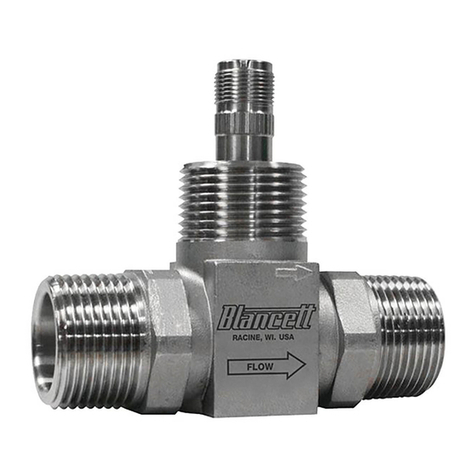
Badger Meter Blancett 1100 Series user manual

Agilent Technologies
Agilent Technologies 5062-8218 Installation note

Chauvin Arnoux
Chauvin Arnoux PAC 20 user manual

Hoffmann
Hoffmann GARANT 44 3450 300 user manual

Polatrak
Polatrak CP-Gun Operation manual
Kingwell
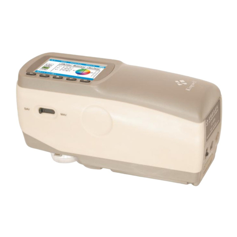
Kingwell 600 Series Instructions for use


